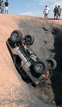
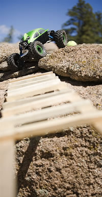
So How Does The Axial Scorpion Stand As A Serious Competition Class Rig? That Was The Question Asked And This Is the Answer.
With Some Small Changes, The Scorpion Is A Top Notch Contender. The Rig Now Works Amazingly Well And Is One Of The Most Capable Rigs We Have Driven. |
|
The key to the build is keep it light and use what works. There are a lot of aluminum upgrades for this or that, super sized drivelines, ect, but keeping it light and nimble is the key to a worthy competition rig.
To date (3 months) the only things needing replacement on our ax10 was the drive shafts and (1) tri-link connector that broke when it fell off of a 6 ft cliff. The axial is extremely durable for an out of box crawler and was obviously well thought out.
I applaud axial on there dedication to build a truly purpose built crawler that works!
|
Ax10 Scorpion
Hpi Bug Body
Mamba Max esc
Brushed!, 45t Integy
CKRC 7.4v 1900mah lipo
Losi rock claws
Super star cut foams
Parts needed for this build:
*(4) Axa1322 70mm body post from axial
*(6) Axa1306 6x6mm spacers
*(1) AX30445 bent links kit
*(4) 3x10mm button head screws
*(4) 3x16 button heads
*(4) 3x40mm screws
*(4) 3mm nylock
*(2) 3x20mm screws
*(8) 3x8mm button heads
*(4) 3x8 counter sink screws
*(1) Pair of hpi 6590 springs
(1) Traxxas drive shafts
(2) Traxxas metal yokes
*15oz of wheel weights
Some lexan and aluminum plate
All items with a * in front of them are in the CKRC STG 2 suspension kit. |
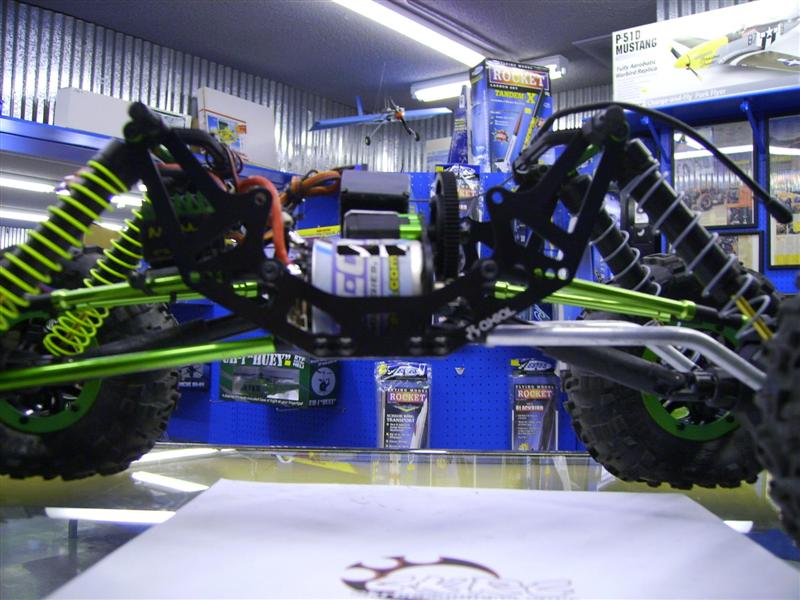
The First Thing We Noticed Was out of the box, the scorpion seemed A Bit Tall and Had Quite A Bit of Torque Twist and rear steer. This is largely contributed to the shorter upper links and the horizontal plane of the links at the factory ride height.
Follow along as we convert an already great crawler into a competition winning machine for very little money. |
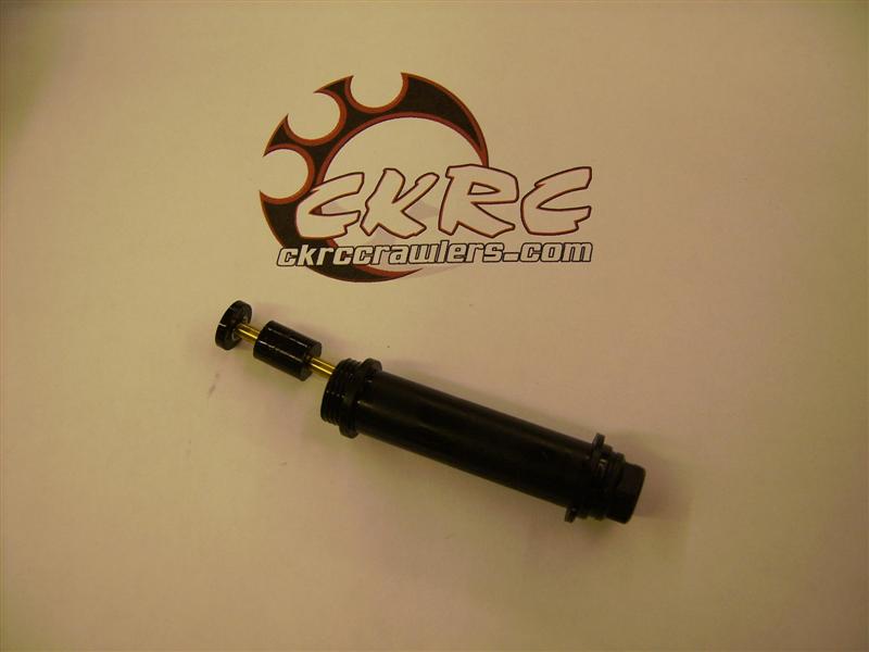
Step 1:
Remove The Shock Damper (axa1358) From Each Shock shaft. These are there to limit your up travel, now we want them to limit the down travel. Pull them off the shock shaft and Re-install them into the Shock body.
This Will Give It a Little Lower Stance and eliminate some of the torque twisting. We Also Noticed It Got Rid of the Sloppy ness In The Middle Of the Shock Shaft And now They Are Less Likely to Leak.
(note) The shock bodies have been known to pop off of the shock caps. If you keep the shock caps tight on the shocks and periodically check them, we have had no more issues with them popping off. |
|
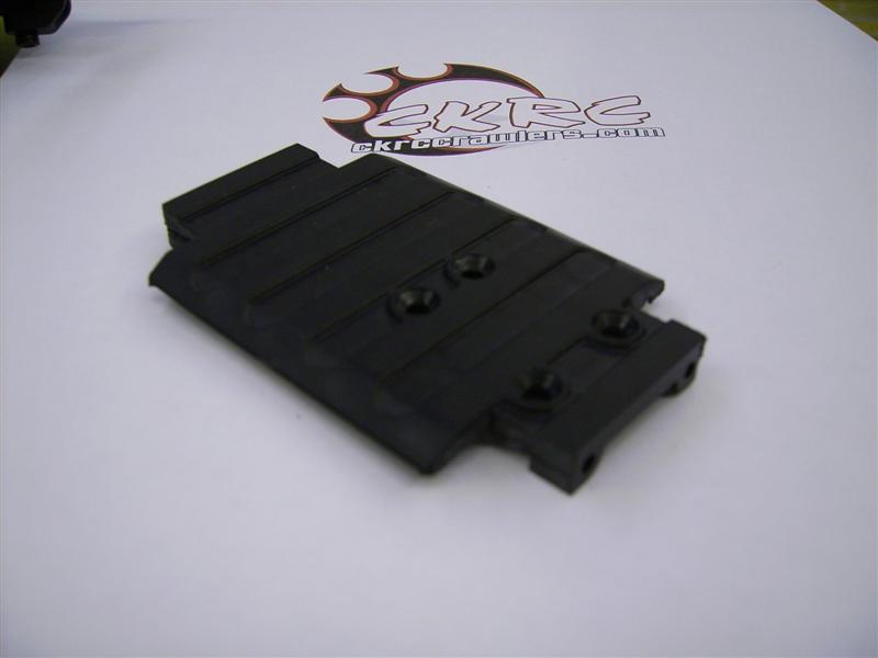
Step 2:
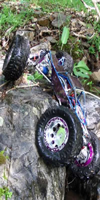
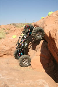
We noticed that the links and link bolts got hung up in the rocks quite a bit. So what we did was modify the skid plate to get the links inside the chassis and away from the rocks. This was also a huge help with angled ledge climbs.
You can see in the photo that there are three holes in each corner of the mount and chassis side plates. Remove just the outer 2 holes off of each skid plate corner. You are leaving the center ones to re attach the chassis to the skid plate. This is what the bracket should look like. |
|
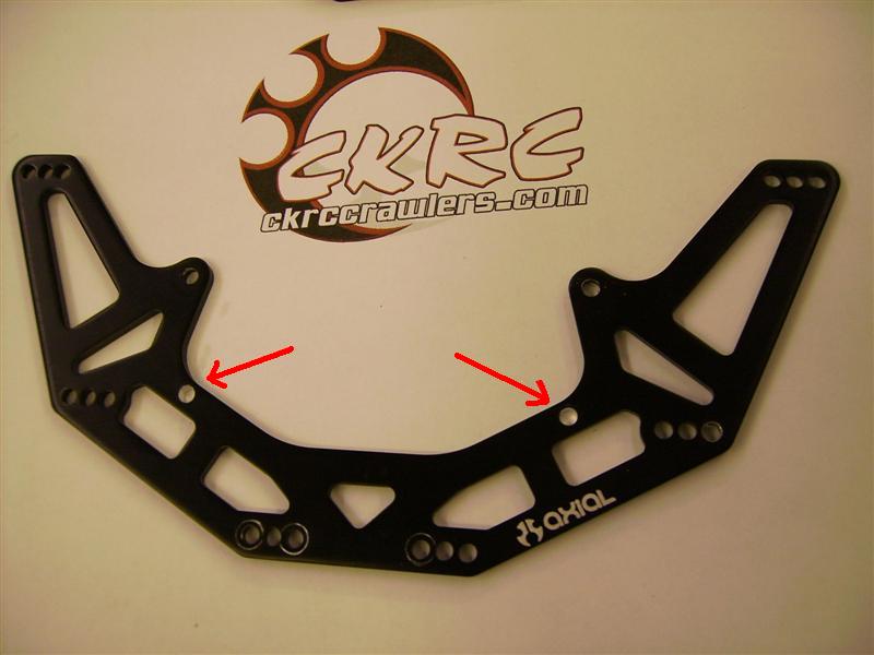
Step 3:
As stated above the upper links are too short and play a large part in the torque twist and rear steer. We simply drilled 4 new holes in the chassis for the upper links and used the following axial parts to extend them. It’s a tight fit when done, but it works much better than stock.
The axial chassis side plates are identical, (ax30480). Mark and drill one hole in the chassis and you can flip and rotate it on the other half to get the holes all matched perfectly. |
|
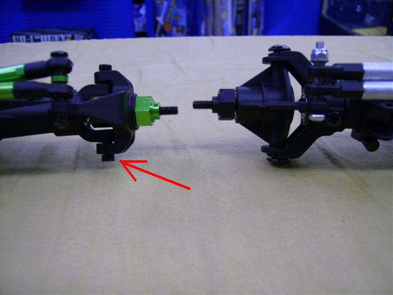
Use the axial 70mm body post (ax1322) to replace the shorter upper tri-link arms (axa1319). When installing into the new chassis holes, you will notice you no longer need the small axial spacers(axa1306). Use the (4) 3x16mm button heads to re attach the upper links to the chassis. Use the (4) 3x8mm button heads to attach the skid plate to the chassis and the (4) 3x16mm screws and nylock nuts to re-attach the lower links to the chassis.
At the back of the tri-link connector (ax80015) you will need to install the small (axa1306) spacer and a longer 3x20mm screw. It has been rumored that the link ball pops out of the tri-link socket. We have not had this issue, but to fix the problem simply install a 3mm washer on the new 3x20mm screw.
This will push the wheelbase out to 12.5” also. |
|
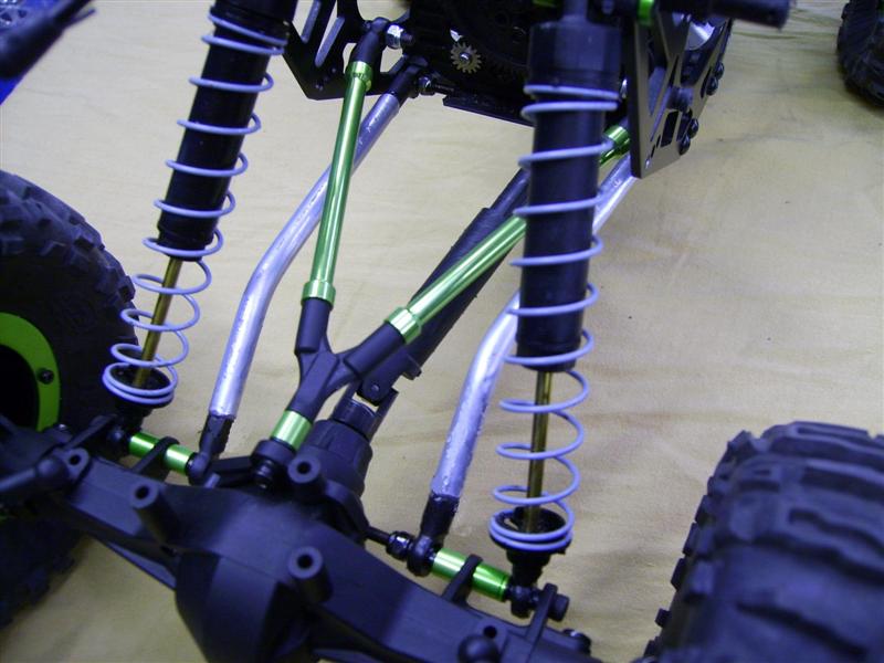
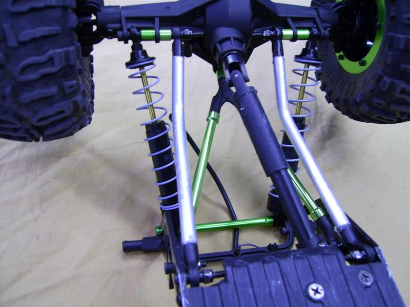
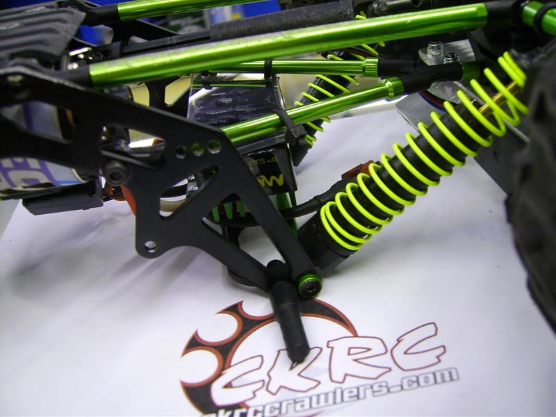
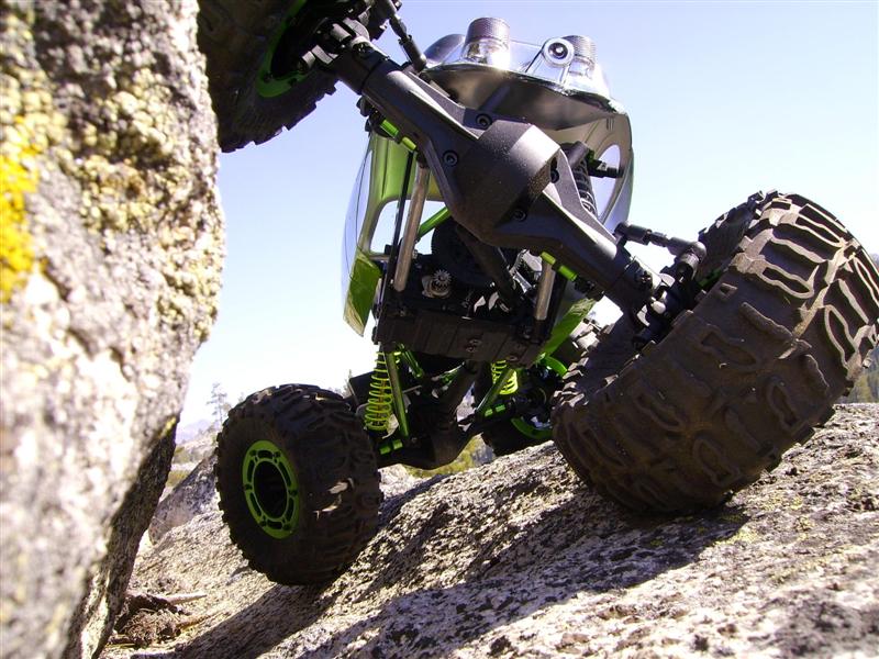
Step 4:
Now to connect the chassis to the axles. We also wanted to get the lower shock mounts moved outboard and bring all of the lower links in towards the drive shafts. This will allow more stability and also help the car from loading up while flexing. You will notice in the pictures how we spaced them in. we used (4) 3x40mm screws to do this as well as more of the (axa1306) spacers. While we were at it we decided to fabricate up some thing similar to the bent link kit axial will have out soon (ax30445). |
|
Step 5:
The axles only needed some minor modifications.
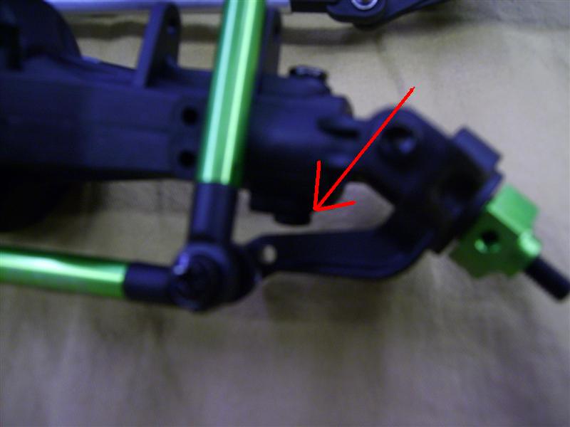
First thing we changed were the lower axle c screws with the 3x10mm button head screws where they attach to the knuckles. This allows just a little more clearance. |
|
Next we wanted a little more steering angle out of the truck. We were ready to modify and grind the stub shafts, but after changing 2 screws, it was obvious we now have more than enough steering. We removed the 2 front axle c screws closest 2 the tie rod. Once out, we counter sunk the 2 holes with a 3/16” drill and then installed new counter sunk 3x8mm screws.
Look at the steering angle! |
|
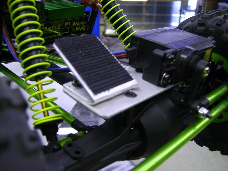
Step 6:
Axial will soon be releasing there servo/battery plate (ax30486). So until then we made up our own for the time being. It bolts directly on, and the only modification necessary is to shorten the steering draglink (ax30442).
For Power and weight savings we used one of our ckrc, 7.4v 1900mah lipo batteries.
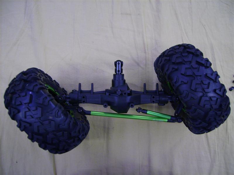
That is it for the axles. |
|
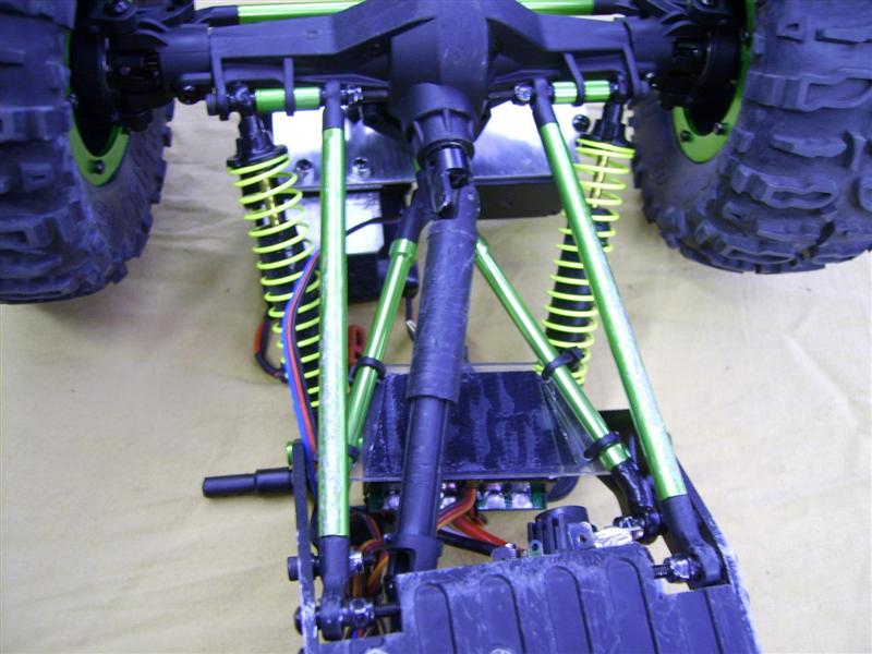
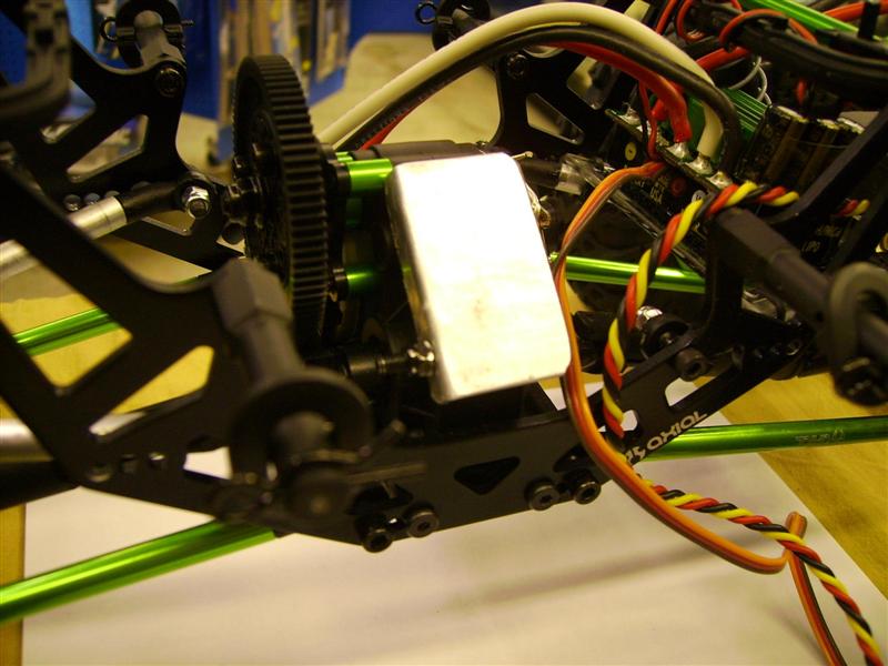
Step 7:
Back to the chassis. We needed a low, clean spot for mounting the spectrum receiver and the mamba max. For the receiver we made a small bracket that bolts directly to the transmission out of 1/16” aluminum. We also made a small lexan plate to mount the esc on top of the front links. We opted to do this to keep the weight towards the front and not extend the mambas wiring. |
|
Step 8:
You will notice in some of the pics, we moved the body post up to some additional holes in the chassis. They seemed to get hung up a lot in the rocks where they were. |
Step 9:
After some testing, we noticed we needed softer front spring to get it to flex better. When we lowered the height and moved the lower shock position out, it made it to stiff, so we used springs from hpi, (#6590) in the front. They are a little shorter, but they work great. |
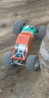
Step 10:
The boss build needed some serious competition tires, so we opted for a set of the new losi rock claws with factory foams. We cut the foams outer diameter to around 3 5/8” to 3 ¾” and removed 5/8” from the width. We then star cut the foams. We finished it up by adding 7.5oz of stick on weights to each front wheel, and drilled (2) 1/8” holes in every wheel.
You can’t go wrong with this set up! |
Step 11:
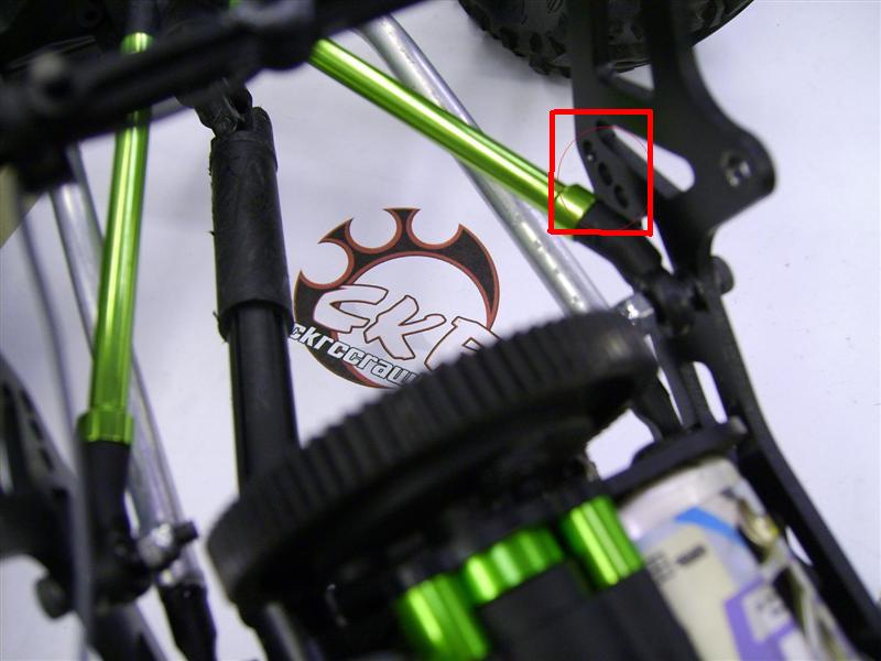
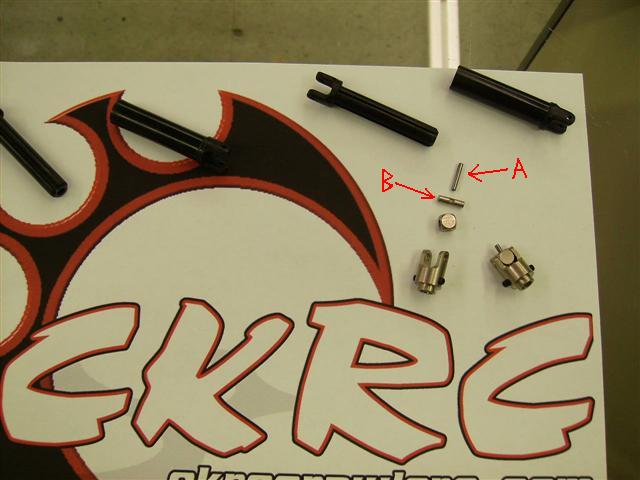
With a little abuse it becomes apparent that the stock drive shafts don’t hold up well. Axial is aware of the problem and will be releasing some HD drive shafts in the future. Until then we have a cure. We used 2 sets of traxxas metal yokes and 1 set of matching drivelines.To date we have had 0 failures. The length of the traxxas shafts is a bit shorter than the axial ones, but we have yet to see a problem.
(note) Do not mix the axial metal yokes with the traxxas drivelines. The problem is the metal yokes cross shaft that goes in to the plastic drivelines is a bit small and short. If you use the axial yokes, the problem still remains. We also recommend using a little red lock tight on the metal shafts where the cross pin goes in. |
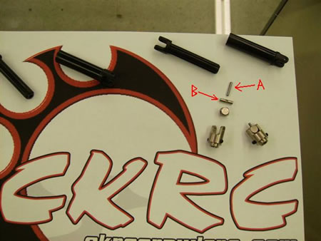
Lock tight (A) where it goes into (B).
|
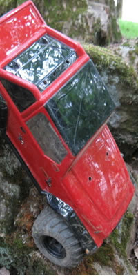
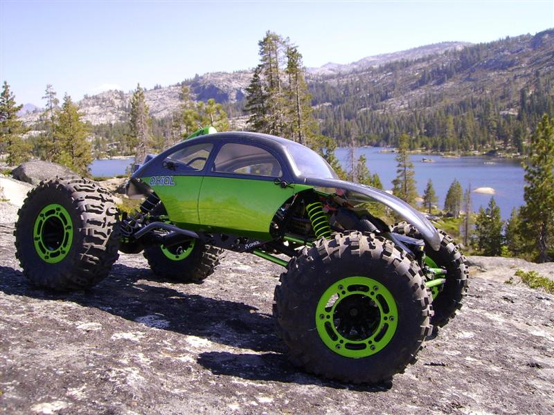
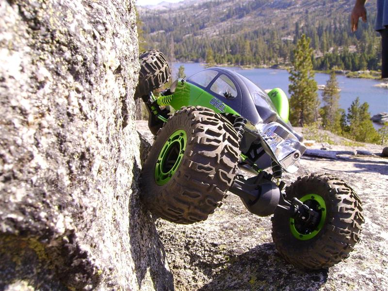
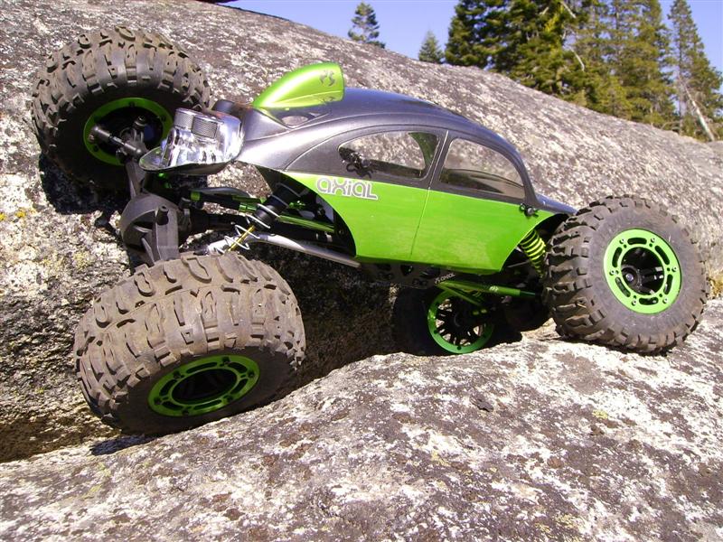
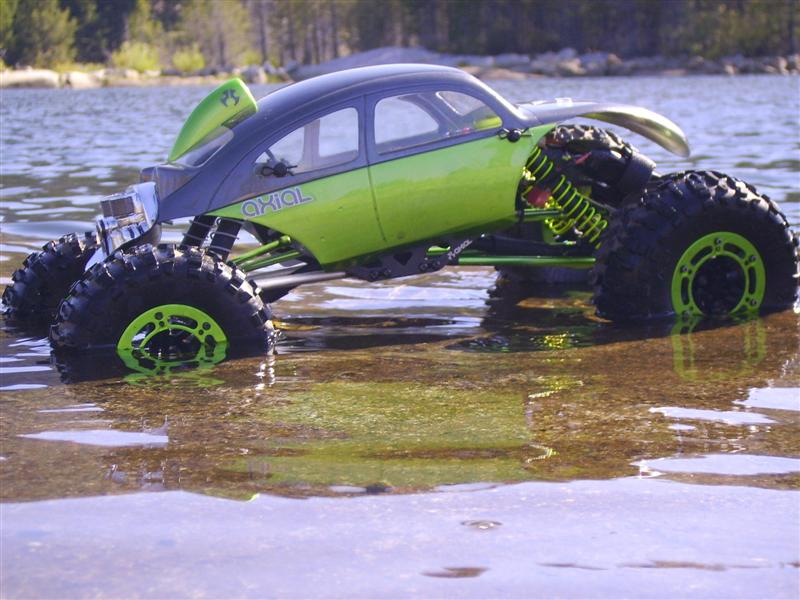
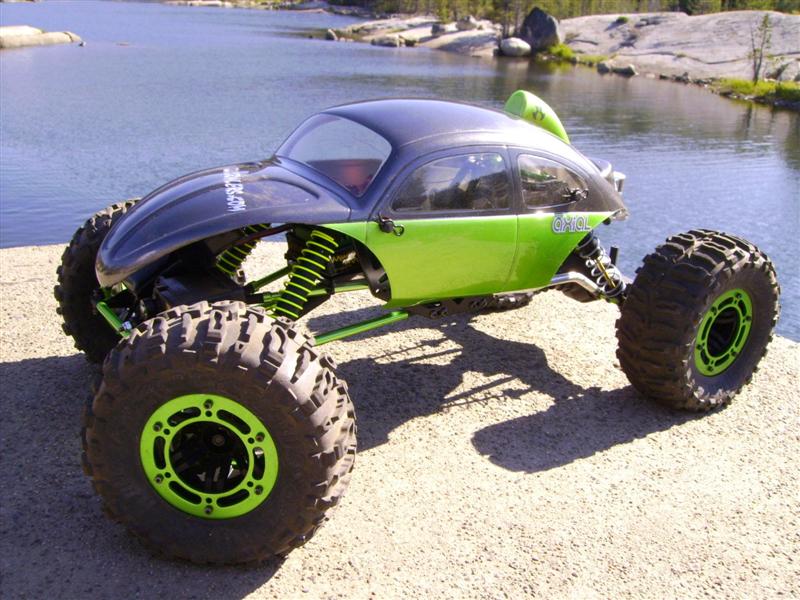
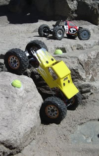
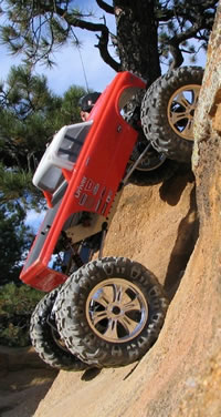
Finish:
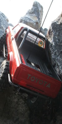
It must not be a comp rig without a bug body! A little axial colors magic and it’s done.
|
|
|
|
|