Tamiya, as always, did a fine job of detailing the assembly of the Clod Gearbox in their manual. So, we won’t go through all the steps described there, but give you some assembly, mod, and parts selection tips to aid you in building what we think is a sturdier and better performing Clod gearbox specifically built for rock crawling. We’ll also try to give you some idea as to which stock parts are strong enough for this use and which could use an upgrade.
Starting with a set of plastic case halves, you can gain a little diff clearance on the bottom by grinding away one of the molded screw tubes as shown here. A Dremel tool does this job well, just don’t cut too deep. This will eliminate one of the assembly screws but you can add a sheet metal screw in the hole next to it.
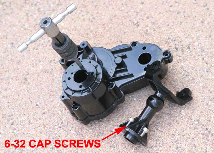
On a stock gearbox, the axle tubes are attached to the case halves with four screws and nuts. When you break an inner axle shaft or axle tube, you’ll have to split the cases to unbolt and remove the axle tube for repair. We like to change that setup. To do so, simply run a 6-32 tap into each of the four holes in each case half. Working carefully with a reversible cordless drill makes quick work of the tapping. Either drill out or tap each axle tube hole as well and assemble the parts using 6-32 x 3/8” long socket head cap screws. Now tube swaps are easily done without splitting the cases.
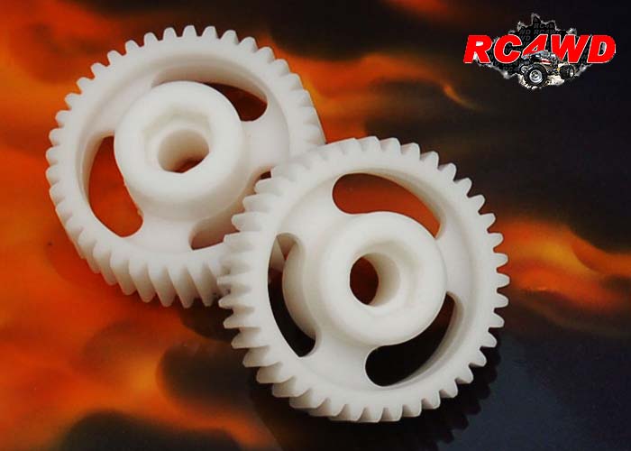
With these mods complete, the gears can be installed, including a locked diff. There are a number of ways to lock the final drive gear as we showed in Six Ways to Lock a Clodbuster Diff. We like the new Delrin locker from RC4WD. The material provides smooth gear mesh and durable hex sockets for the axles.
When installing the gears, use a light coating of grease on the gears. It doesn’t take a lot to keep them spinning smoothly, so don’t pack the case full. The Tamiya grease works well as do most light-weight greases (white grease, silicone based grease, etc.).
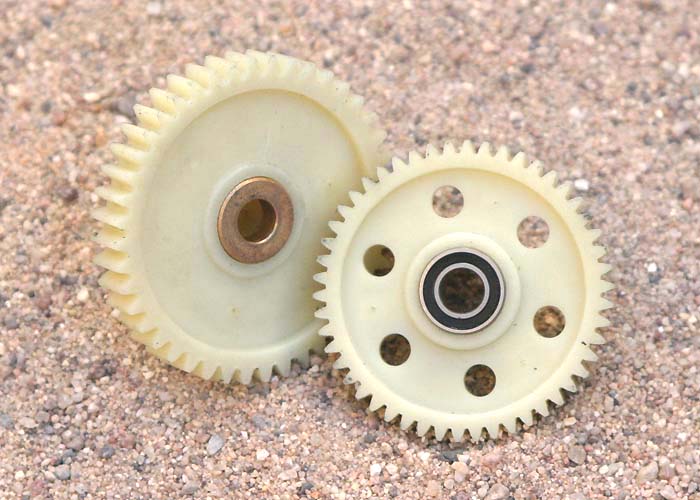
Since we’re building a crawler and not a high speed race machine, the use of bearings in the gearboxes is not absolutely necessary. If you typically run in a lot of water or muddy conditions, you may want to consider bushings over bearings, as they usually last longer and do not corrode as the bearings will eventually do. Bearings are also more likely to fail more suddenly whereas a bushing will wear more consistently over time.
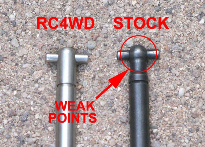
The stock Tamiya axle shafts are fairly strong but the inner shafts can break near the weak cross-pin area and the outers can bend over time or during a hard fall. RC4WD sells a replacement set built from stainless steel and the weak dog bone area on the inner shafts has been strengthened.
The stock plastic axle tubes are quite strong and will seldom, if ever, break at the case end. However, they can snap off at the outer ‘C’ area where the knuckle attaches. Aluminum tubes can be used but are typically not needed. Aftermarket knuckle braces are also available that fit inside the ‘C’ area, but may limit turning angle and are often more appropriate for racing trucks.
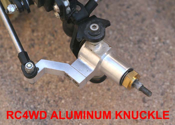
Moving outward to the knuckles, our goal is to maintain strength and obtain a tight turning radius. If you’re running stock plastic knuckles, cut off all four stop pins to maximize your ability to turn. The stock axle shafts will handle the extra angle with no problem. While the main body of the plastic knuckle is sturdy, the steering arms can break under hard landing or stress. Due to this, aluminum knuckles are a good option to prevent this problem.
We should mention another option available for adding both strength and tighter turning is the replacement of the stock axle shafts with a set of CVD axle shafts from Thundertech Racing. These kits offer axle shafts that are stronger than stock, add ¼ inch width to each side, offer sharper turning, and smoother power transfer over the stock pivot style shafts.
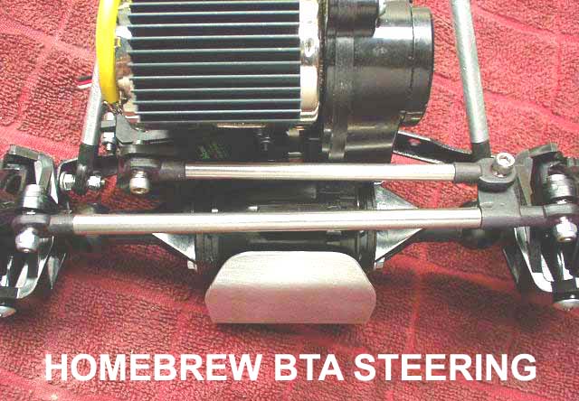
With the axle assemblies complete, it’s time to choose a steering setup. For a comp rig, it’s an advantage to remove all the steering linkages from in front of the front axle. This greatly reduces the chance for damage to the steering linkage and, more importantly, provides better approach angle clearance. Behind-the-axle (BTA) steering setups put the steering linkages to the rear of the gearbox, up under the motor.
Thundertech Racing makes their Aggressor kit shown here which uses a carbon fiber tie rod. Those that are handy with a few tools can make your own servo mount and steering rods. The trick is making a setup that is tucked out of the way and provides sharp turning ability. When the steering is installed, ensure that you get full turning movement from your servo and linkage setup. Components can bind or interfere with the gearbox and limit your true ability to turn sharply. With some knuckles and axle sets it may be beneficial to trim the backside of the knuckles to improve the turning radius.
We’ll also mention that we’ve found that the steering linkages on the rear gearbox are best left all the way to the rear, rather than tucking them forward under the motor. Since most driving is done going forward, having the linkages on the rear leaves less chance for the rear gearbox to hang up on rocks going forward. There are a number of quality aftermarket mounts, or you can fabricate your own.
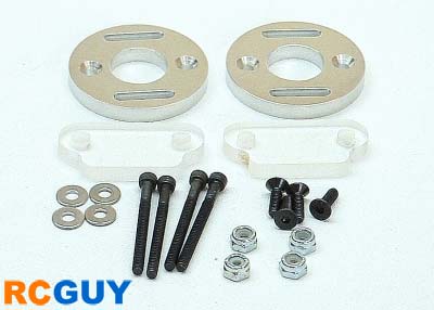
When setting up steering for a crawler, beefy servos make all the difference in the world. That is, provided you have the supply power to run them under heavy loads. As such, make certain that whatever style servo mount you use does not flex much under load. If it does, you’ll be wasting vital steering ability. Usually a well placed brace or third attachment point can eliminate any mount flex you may have. Here we also show the generic flat RC4WD brace that lays a little closer to the axle tubes than a stock piece to provide room for mounting a servo or batteries.
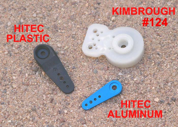
When it comes to servo arms, there are several choices and schools of thought. One can use either a spring-loaded servo saver, a plastic arm, or an aluminum arm. The goal is to provide strong, predictable steering while also providing some safety against destroying the servo gears from a hard impact transmitted from a tire back to the steering linkage and servo. Servo savers provide the greatest protection to the servo gears, but their flex also diminishes how well you can steer the tires and hold a line in the rocks under heavy load.
Our experience shows the Kimbrough #124 is one of the most effective savers for this application, and the action can be further tightened a bit by filling the spring cavity with silicone sealer. The large Ofna savers have a tight mechanism but the plastic used is relatively soft and can flex if the linkages are not setup parallel to the saver.
The use of a solid servo arm is a step up in providing a rigid steering setup that can put the maximum torque of the servo to the tires. However, without the safety vale of a saver, the servo is more prone to damage. Running a plastic servo arm is a compromise that provides a solid link with the thought being the plastic will snap in two under an extreme load to the servo. We have seen this effective in action.
We’ll also briefly mention the plastic wheel hubs that mate to the stock Clod or Bullhead wheels. In our experience, these tend to be plenty strong and the mating pins on the backs of the wheels are more likely to break. Still, the aluminum aftermarket hubs are cool, just probably not necessary for strength. If you’re running any of a number of aftermarket wheel adapters, you probably won’t even be using the standard wheel hubs anyway.
The final additions to our gearbox are motor and gearing. The stock gearbox is setup to run a 13T (tooth) pinion, which is geared way too high for a crawler, and there are not slots provided to allow for pinion size adjustment. It is possible to cut additional holes or slots in the plastic case to accommodate other pinion sizes, but here it often makes good sense to purchase an aftermarket adjustable motor mount. These usually have a slotted aluminum mount that bolts to the case and a clear plastic window that allows you to see the pinion gear for setup.
Rock crawler pinions usually range from about 6T to 11T, based on tire size, terrain, motor, and battery voltage. To set the pinion height from the motor can, Tamiya included their little metal tool to set this measurement. With a slotted motor mount you’ll need to adjust the gear mesh, or how tightly the pinion and plastic spur gear come in contact with each other.
Many drivers set this by feel and visually watching that there is just a little play between the two gears when rotated back and forth. One trick is to set the distance between the two gears by squishing a piece of paper between the teeth. Also, by setting the mesh just a bit on the snug side you can create a bit of drag in the gearbox, effectively serving to slow the idle rotation of the gearbox as you’re coming down super steep rock faces.
Hopefully we’ve given you some ideas on how to maximize performance from your Clod gearboxes with an eye towards building a competition worthy rock crawler. In a future article, we’ll delve deeper into what parts and mods gain you the sharpest steering ability for your Clod gearboxes.