| |
| |||||||
 |
| | LinkBack | Thread Tools | Display Modes |
 10-15-2008, 10:07 PM
| #1 |
| Quarry Creeper Join Date: Sep 2008 Location: Petaluma
Posts: 282
|
Hi ALL - long time viewer - first time builder! Just got into building this Tamiya F350 High Lift and thought I'd share it's progress. It only lived for 2 days (without any electronics but built) and then was disassembled for the redo. A bit nerve racking dropping a lot of $$$'age only to cut it up but I'm hopeful the end result will look cool and unique. This is the roof rack but more will follow. It's not 100% done - will still put in the screens but I can do that later once more other things get built up more. This will at least offer me an opp to do other stuff that's on my mind. Hope the pics are OK. BUILDING THE F350 ROOF RACK 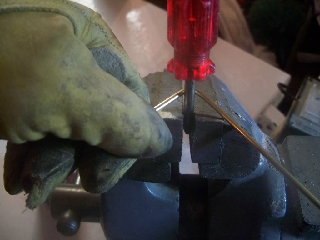 I continued doing this while tracing the roof line one bend at a time until I reached the half way mark. Doing it this way I was able to get the right bends and gave it a custom look by adding a little extra bend to accent the roof line. 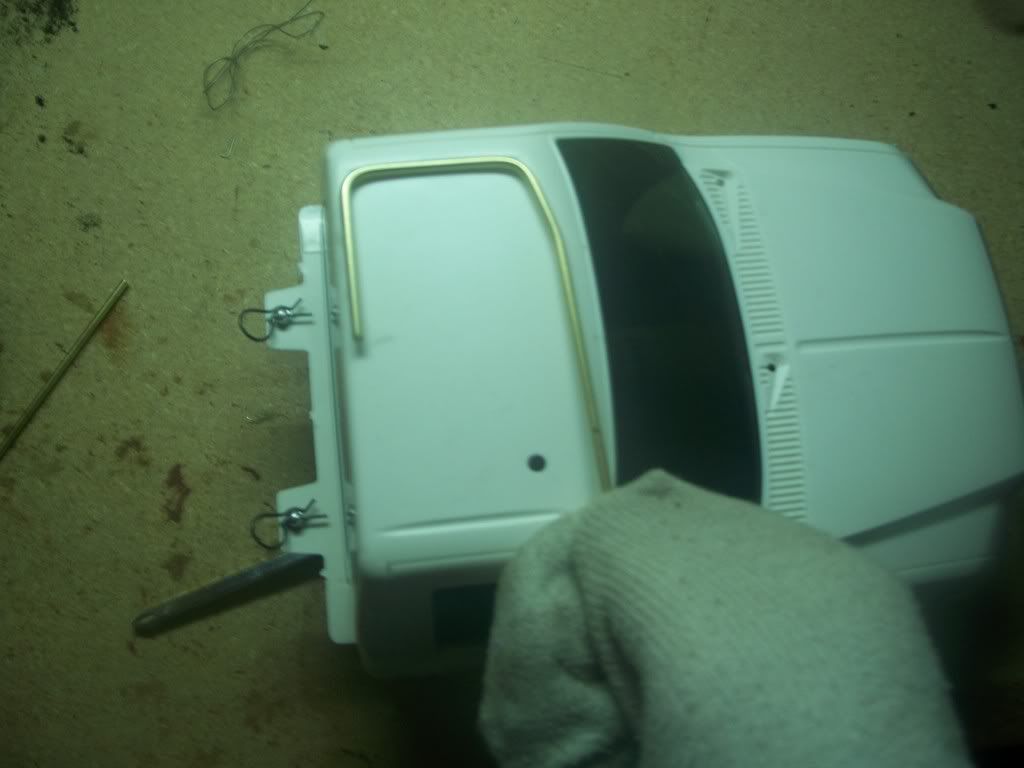 With 50% done - it was a matter of duplicating it on the other side. I just outlined the already made bend tube and matched it to the other side by flipping the metal around. 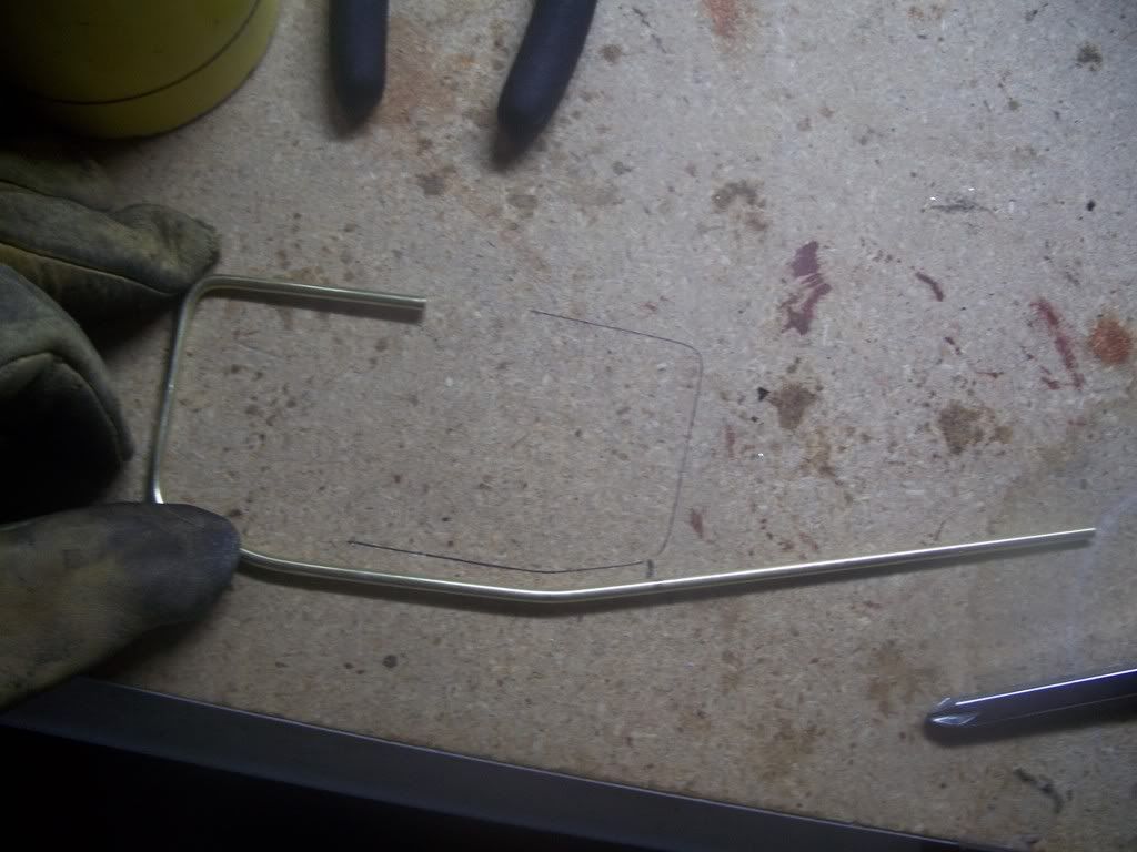 Sometimes you get lucky and without measurments - things turn out just about right. A little snip of the end to reduce the overlap and braze and one tube construction was finished. Although never brazed before - it was a bit messy... 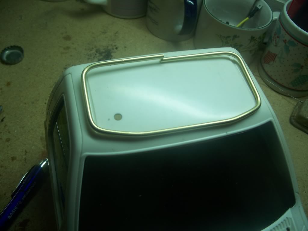 Now to duplicate it onto another piece using the first one as a template. By wireing the new to the old, I was able to replicate the second level of the roof rack very easily and it was done in no time at all. 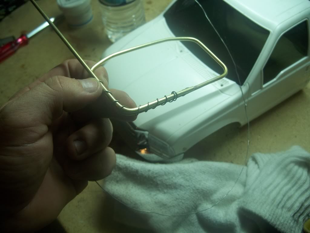 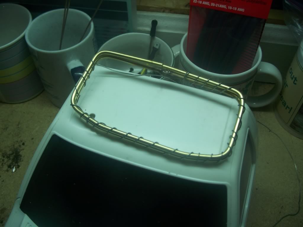 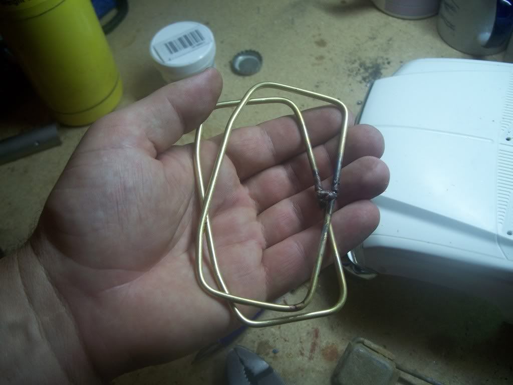 A sloppy brazing job for the first attempt but after a $19.95 dremmel tool with a grinding wheel from Harbor Freight Tools, it looked pretty seemless. Now to measure the height - but who needs a ruler - lets just size it up by looks. 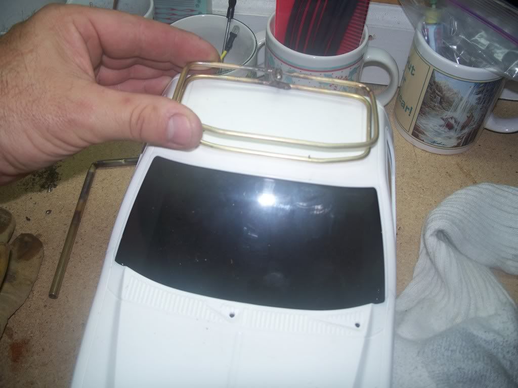 Sorry for the out of focus pics but you get the idea. I used another stock piece of brass from the hobby store and nipped a section out. It seemed like the right size so I duplicated it for a total of 4 pieces. This was to support the RT and LFT sides and back. The front - I decided to just double the size of one piece so it was a bit consistant in size. 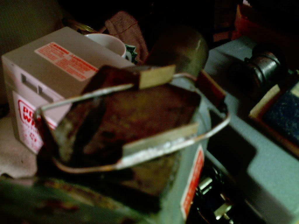 With a few sides brazed on, I was able to slip the top rail on and the supports held it in place without needing to be held so the second level of the roof rack was a bit easier to weld. 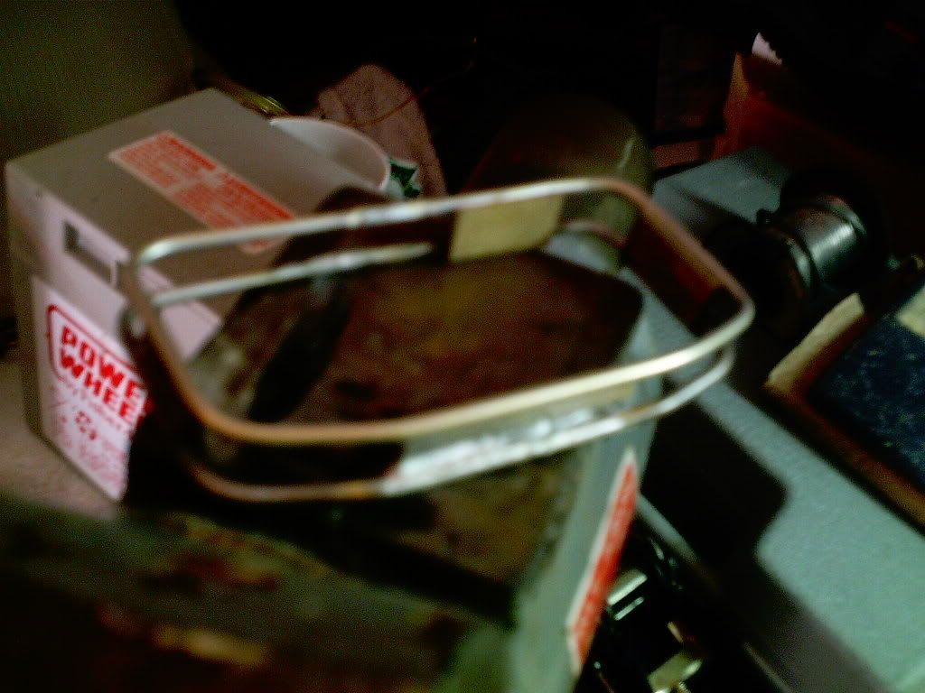 Now I added the back piece and the basic construction was finished. Pretty easy but I think it needs more. 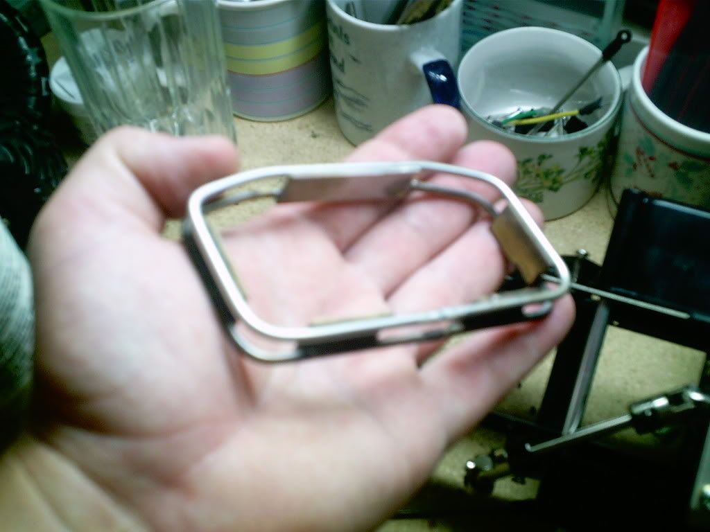 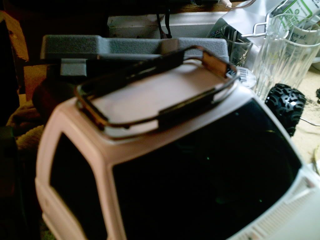 How about some lights? 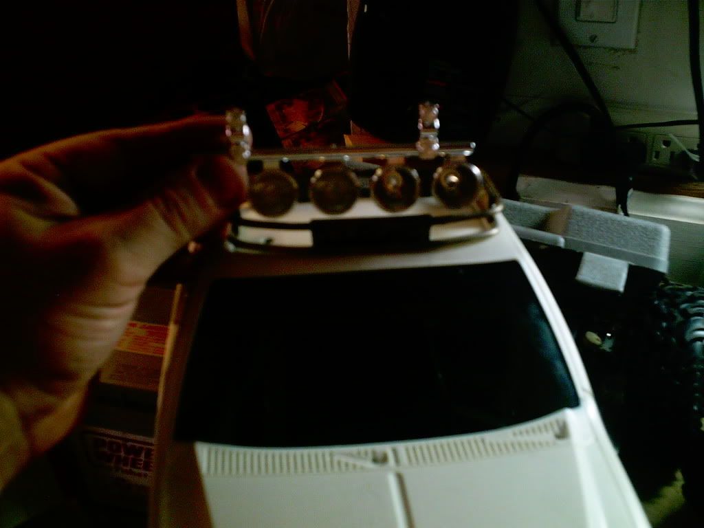 4 lights looks pretty cool - maybe just 2 - not sure... the only way was to cut the lights from the roll bar and pray ! After several bleeding seconds of cutting, I seperated the lights and placed a few here and there to try and figure out the best configuration. The idea of placing a hard top crossed my mind but after searching and searching for a hard top for the bed - the idea was to fabricate a soft top and go ahead and use the cargo roof rack to support the off raod lighting. I decided to go with 4 lights but after placing the lights to the rack - the lights needed a bit of protection from low lining trees and such.  lastly a couple supporting brackets for the top light protection bar and slap on some flat black paint. At least the idea is cool. 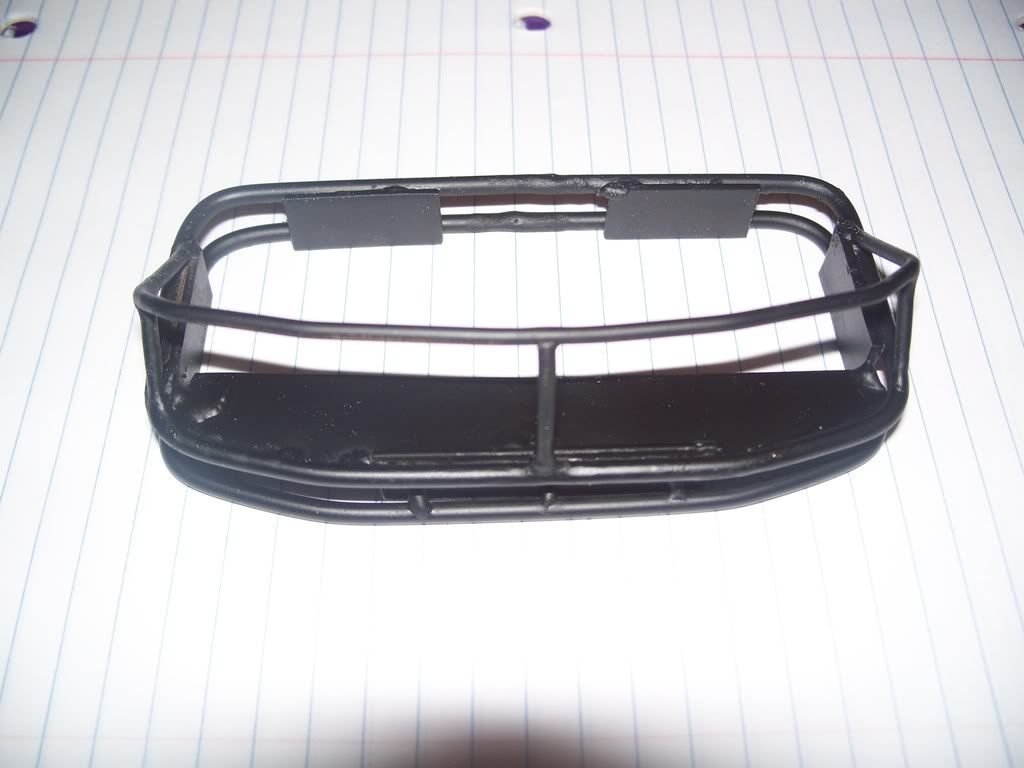 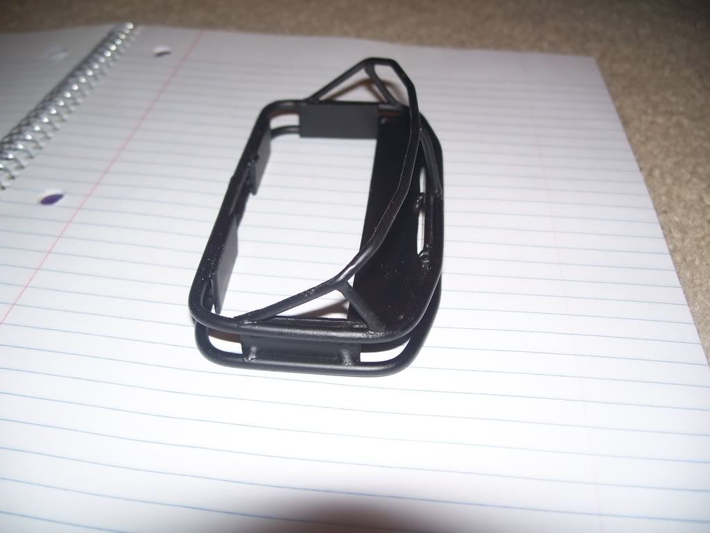 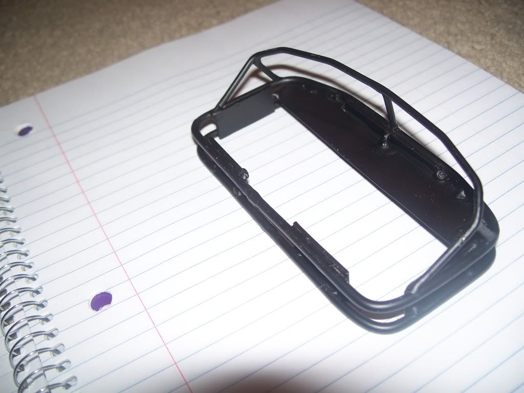 By adding a thin brass cross member, this will ultimately support the lights. 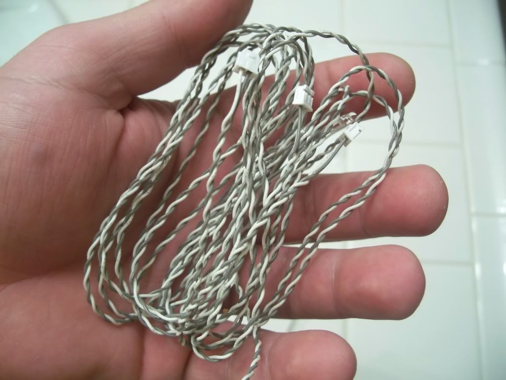 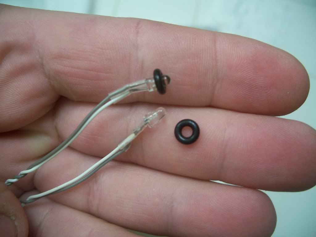 To add the lights that came with the truck - I purchased the MFC-02 unit so that I can turn them on remotely from the transmitter. I liked the entire package of the multifuction control unit (not just the lighting) so I went the whole 9 yards. After cutting down the lights from the roll bar (a bit scary at first) I filed down the remaining bottom part from the light. I left two of the light supprt with just a little portion of the rool bar attachment left and filed the other two to the nub. This was to make sure the center lights fit a bit higher than the outer lights as the top portion of the roof rack bar tilts down ever so slightly towards the lateral sides. The small "T" support under the light was trimmed using an exacto knife and then I found the "smallest" drill bit I could find at the hardware store and started to "hand turn" the bit until it pierced the light. I didn't want to use a power drill and take the chance of pushing the bit throught the top. 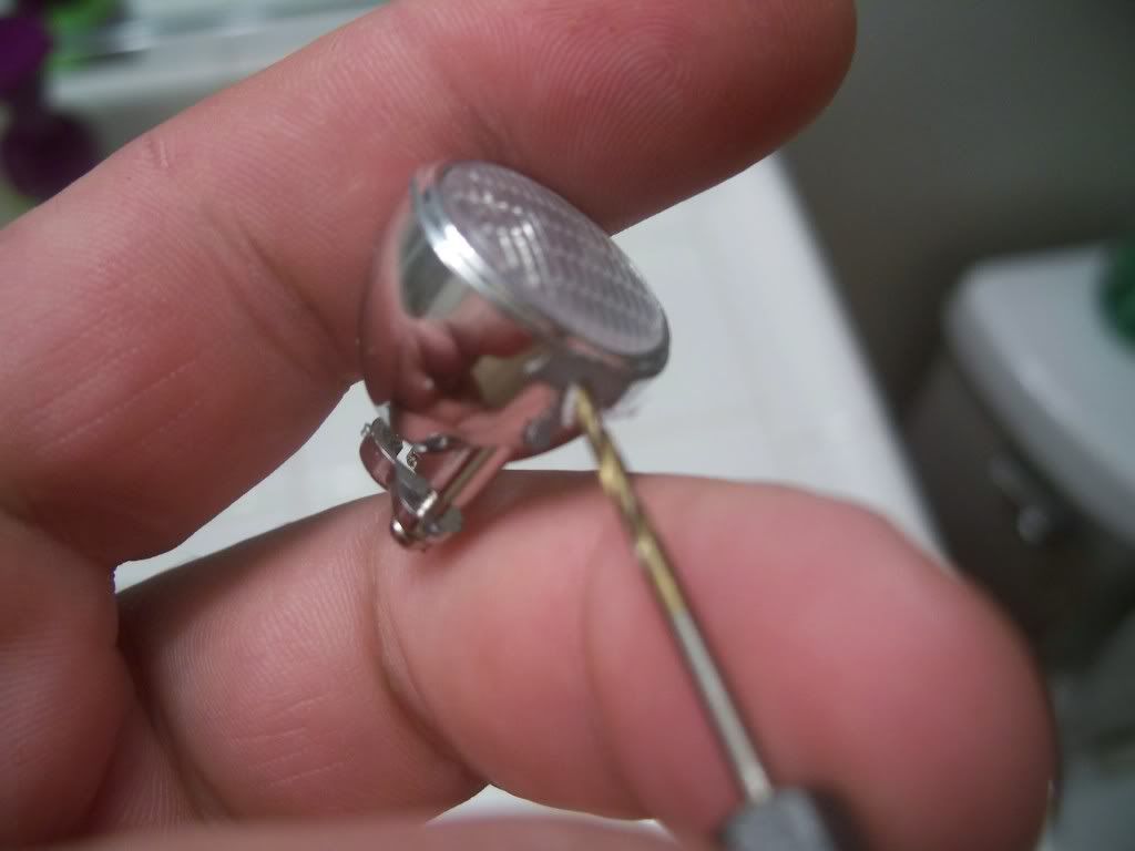 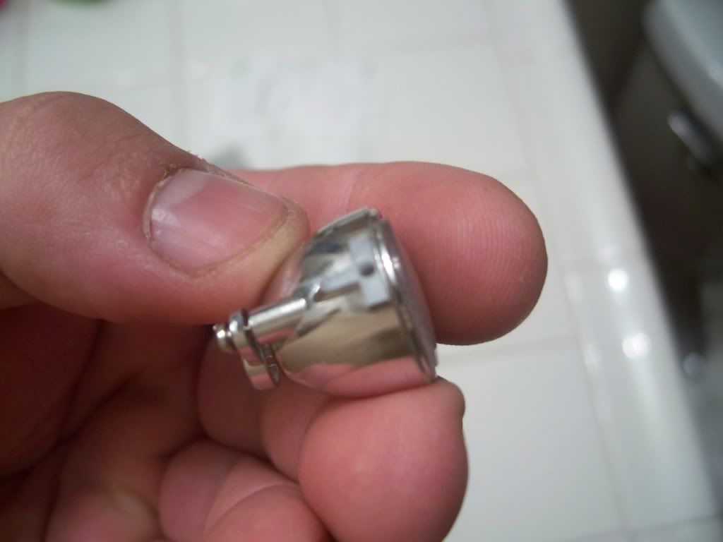 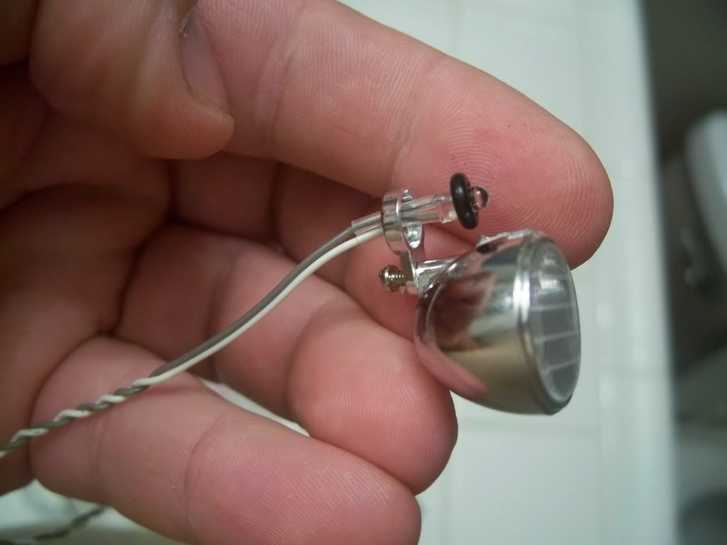 careful measuring up the lights (eyeballing 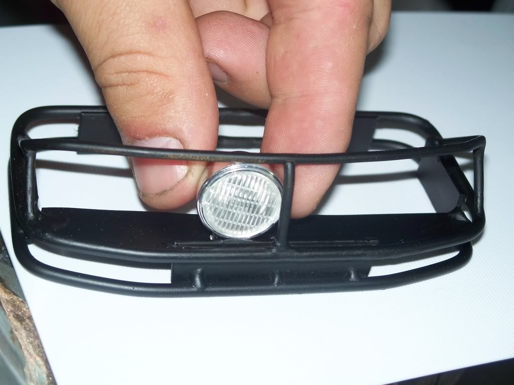 and then... I was basically done. I still have to attach the bottom screen, drill the bottom screen hole for the wires to thread into (which just so happens to line up with the pre existing antenna hole in the roof (I planned to fill but now don't have to) and paint the bottom screen with a caot of flat black. I'm thinking I might shrink tube the light wires just to give it that clean built look. 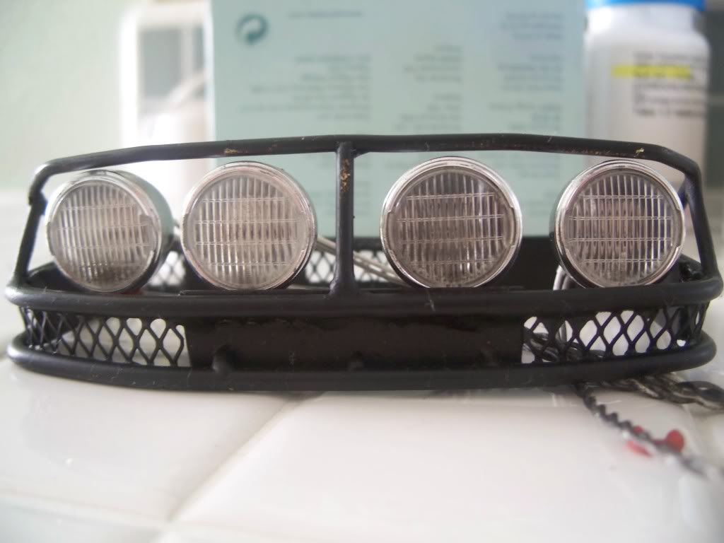 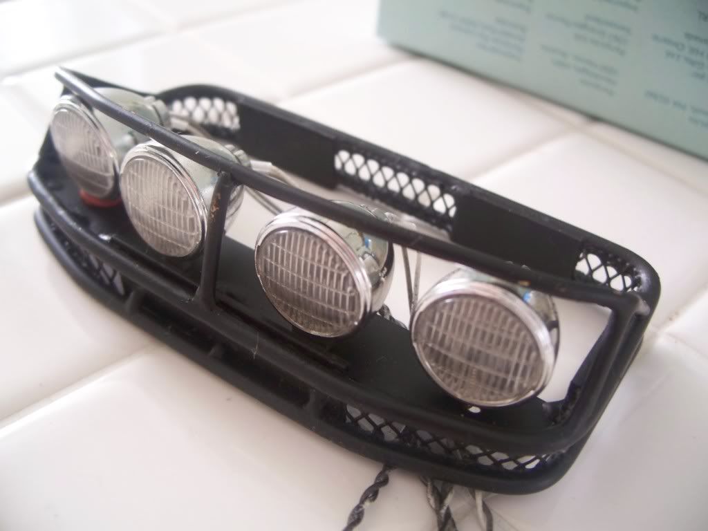 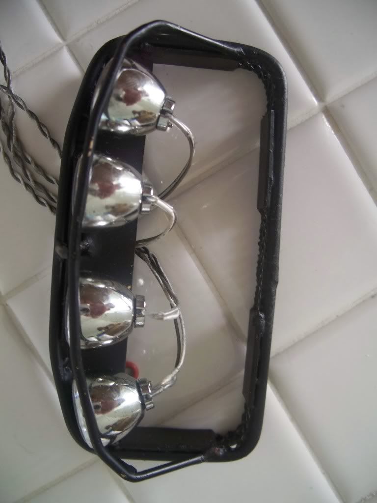 Using the red (extra) rubber bushings from the shocks (those I'm replacing) I placed them on the "outer" lights only to give them just a little support seeing I cut the original light supports off to the nub - it really didn't add any extra height as they scrunched down pretty good with the screw (Oh yea forgot to mention the screw) from below. BTW - those screws I used are the "extra" ones the kit includes (those for attaching the diff cover plates). 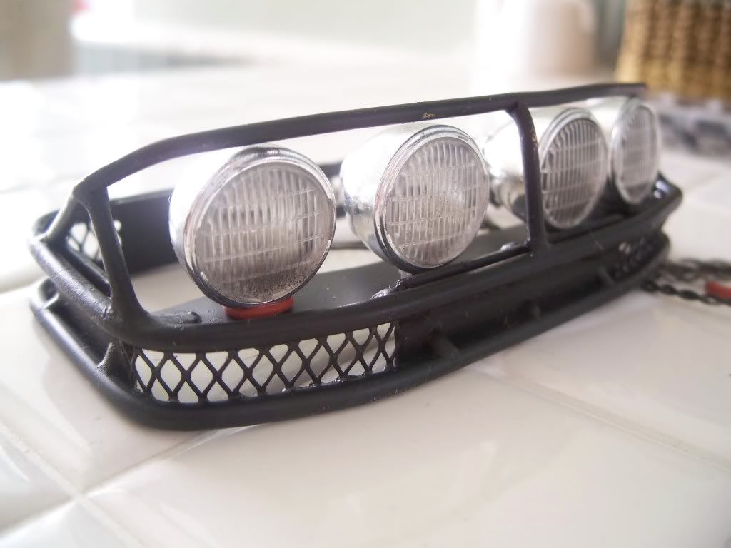 Cool huh??? Last edited by FodigoDave; 02-13-2009 at 10:42 AM. |

|  |
| Sponsored Links | |
| | |
|
10-16-2008, 12:40 AM
| #2 |
| Quarry Creeper Join Date: Sep 2008 Location: Petaluma
Posts: 282
|
Sorry about the majorly LARGE pics - I 'll try to reduce those for future postings. I have in progress a redesign of the rear suspension (converting the leaf spring stock setup to a 4 point) and covering the f350 HL truck bed with a brass metal (brazed) framework skeleton and soft top setup. I'll post shortly new pics in case anyone's coming upwith the same idea so we could toss around ideas together.  Good luck with your F350 HL's build! Stock is great but Trick is just so much better - especially when you design / build it yourself. Last edited by FodigoDave; 10-16-2008 at 12:42 AM. Reason: additional comments |
|
| |
|
10-16-2008, 02:15 AM
| #3 |
| RCC Addict Join Date: Jan 2008 Location: Wetlands
Posts: 1,014
|
Lookin and a likin'.........Picking up some Ideas as you go along.
|
|
| |
|
10-16-2008, 06:04 PM
| #4 |
| Rock Crawler Join Date: Sep 2004 Location: South Orange County
Posts: 589
|
you have got some skill
|
|
| |
|
10-16-2008, 06:27 PM
| #5 |
| Quarry Creeper Join Date: Sep 2008 Location: Petaluma
Posts: 282
|
HOT TIP Never throw anything away - I just happened across some old gutter guard (aluminum metal mesh) that is very scale for the 1.9's (although it was trash about a year ago - it never found the can (LOL)) and good news for me [the recycler...now] Although aluminum wont braze to the brass - I plan on epoxy glueing it in for the bottom and vertical gaps between the rails. I sized it up today but plan to install tomorrow. I thorow up some pics when I get it started. (BTW - you can buy this gutter guard stuff for about 2 bucks from your local hardware store) |
|
| |
|
10-16-2008, 06:59 PM
| #6 |
| Quarry Creeper Join Date: Apr 2007 Location: St. Louis
Posts: 267
|
I know what you mean about a lucky find. I found some perfect sized mesh but the problem was that it was non-magnetic stainless. :-( Can't do anything with that as in I can't solder or braze it to a steel frame.
|
|
| |
|
10-16-2008, 11:14 PM
| #7 |
| Quarry Creeper Join Date: Sep 2008 Location: Petaluma
Posts: 282
|
Screens on Roof Rack finished but not painted . Will take pics and post tomorrow. Looks totally scale - really nice.
|
|
| |
|
10-17-2008, 02:19 PM
| #8 |
| Rock Stacker Join Date: Apr 2008 Location: Salt Lake City
Posts: 85
|
Nice work
|
|
| |
|
10-18-2008, 07:50 PM
| #9 |
| Quarry Creeper Join Date: Sep 2008 Location: Petaluma
Posts: 282
|
Found some of the older pics - I was looking for but couldn't find - that are a bit more clear before it was painted. Also installed the screen so that shots in there too. I have yet to install the lights, drill the wire hole in the bottom screen and mount. Will likely do that towards the end of the entire build. Next is the trucks 4 point system in the rear . The travel just wanst cutting it. 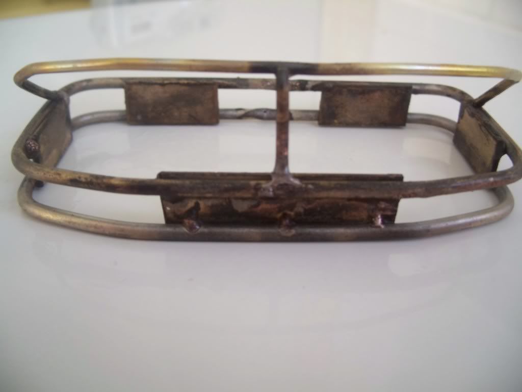 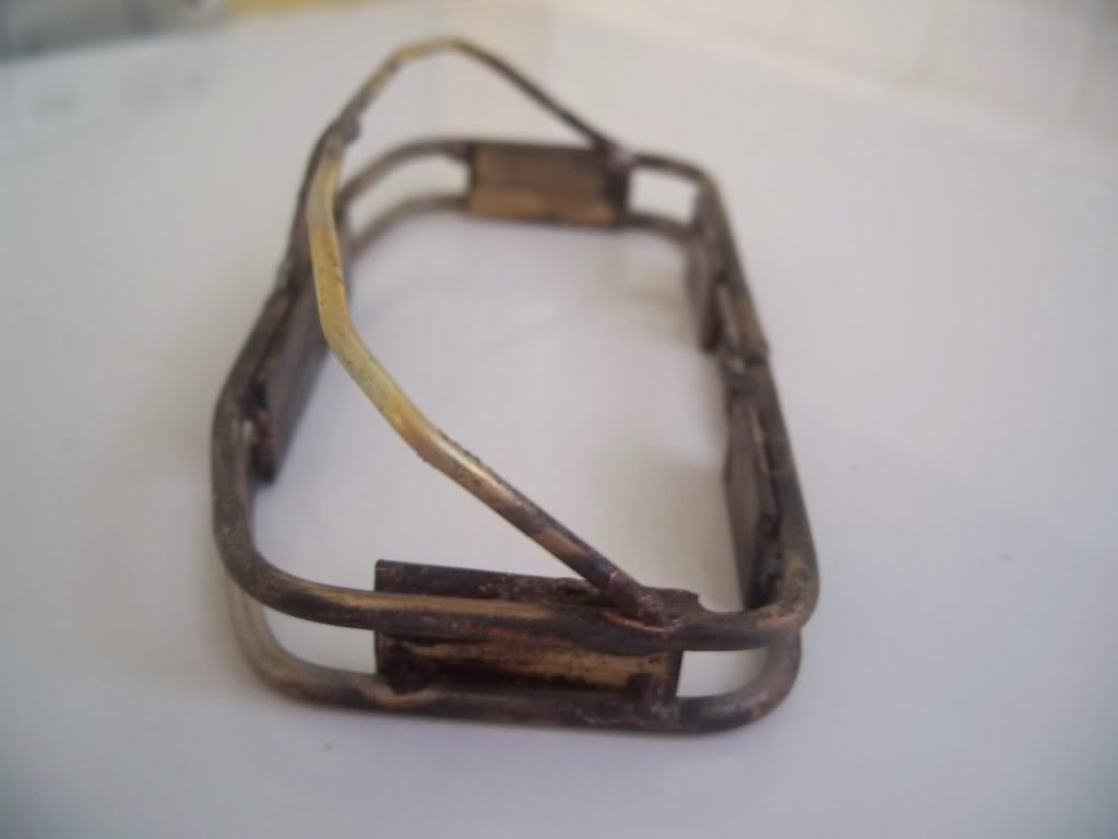 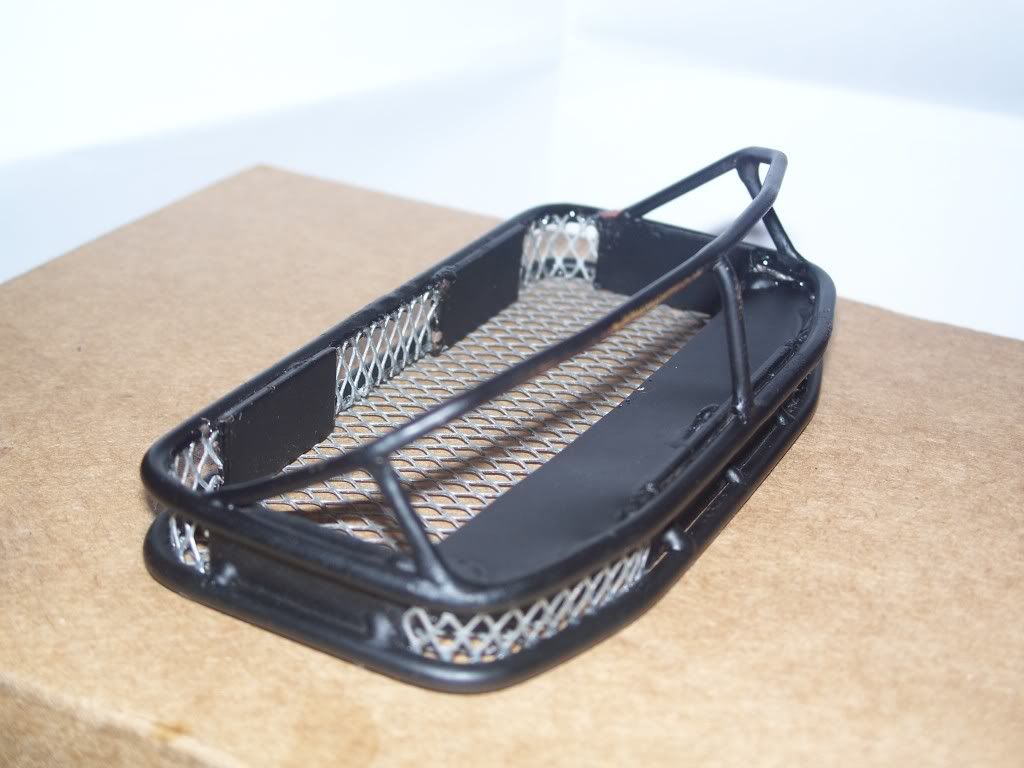 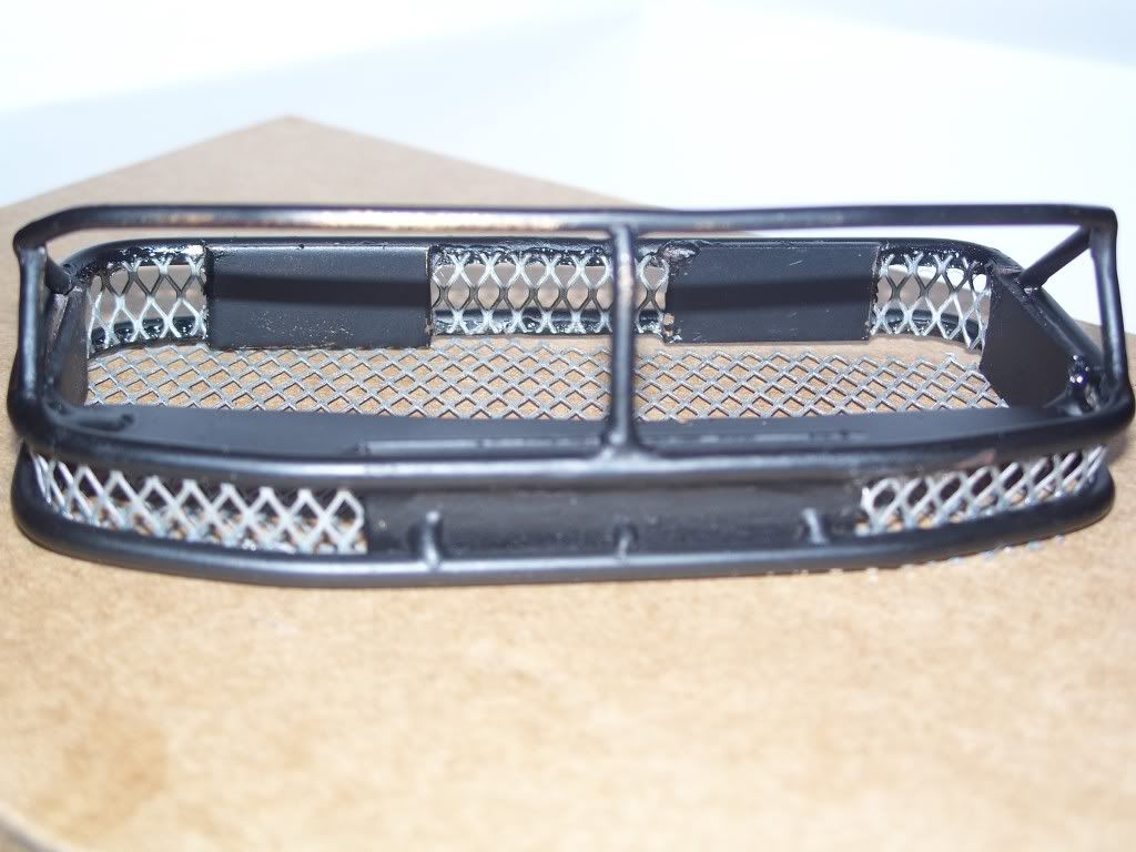 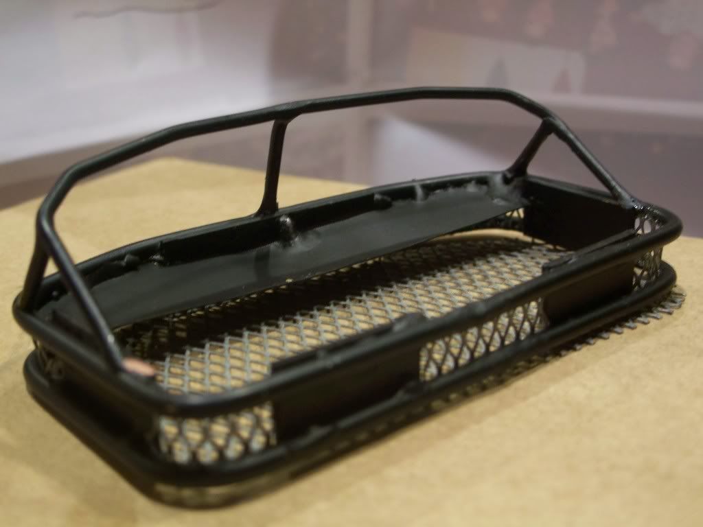 The bottom piece isn't mounted yet. Last edited by FodigoDave; 10-18-2008 at 08:34 PM. |
|
| |
|
10-18-2008, 08:22 PM
| #10 |
| Quarry Creeper Join Date: Sep 2008 Location: Petaluma
Posts: 282
|
Real sorry for the giganto pics - I'm lucky jus to post them. The 2 day after the finished stock build gave light to the limited suspension the F350 high lift has right out of the box. Although I understand - after a little while of running it, the suspension loosens up but the leafs break. I took the truck in it's stock "finished" form before the mod building (still in progress) and put it on several sized challenges. Aside the rear coming off the ground with a front rock challenge of minor height - the truck failed in my opinion, hense the idea of rebuilding the rear end for more travel. The front - I'll keep stock. I haven't figured out the right solution for ground clearance other than bringing in some 2.2 rims and tires but the suspension mod will sure help with the travel. For now - the stock 1.9 rims from rc4wd will do jus fine. I'll have pics of the weight build for those shortly. I started out with the idea of just using the stock (extra) brackets the truck came with and adding a center (top) bar. 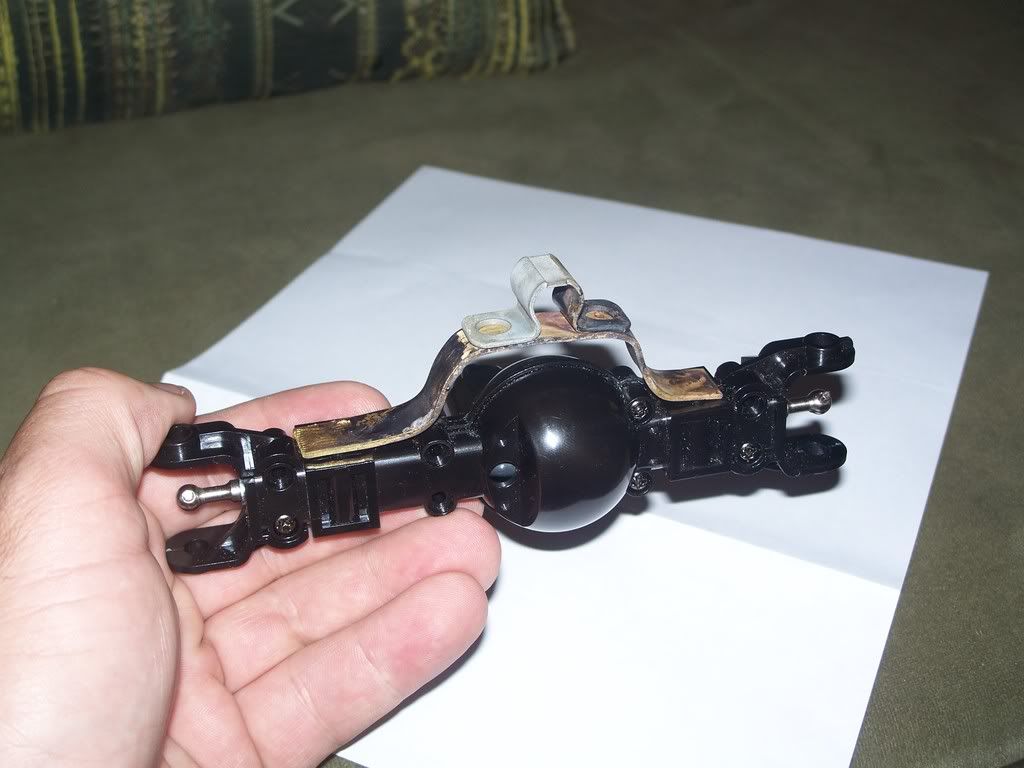 After I slept on the idea - I scratched it and was glad I did later (certainly not during the design process - cutting galvanized metal isn't the easiest). The idea was to plate the front and mount brackets for the swaybar and track bars. I started by visiting my local hardware store for some scrap / bulk sheet metal. I ended up spying an "L" bracket for a deck. galvanized and hella stong! with about the right amount of thickness (about 8th inch). I used a carboard design then cut out a rough cut onto the steel but had to remove the "ribs" on the axel first as this is where a part of the front bracket was to live. 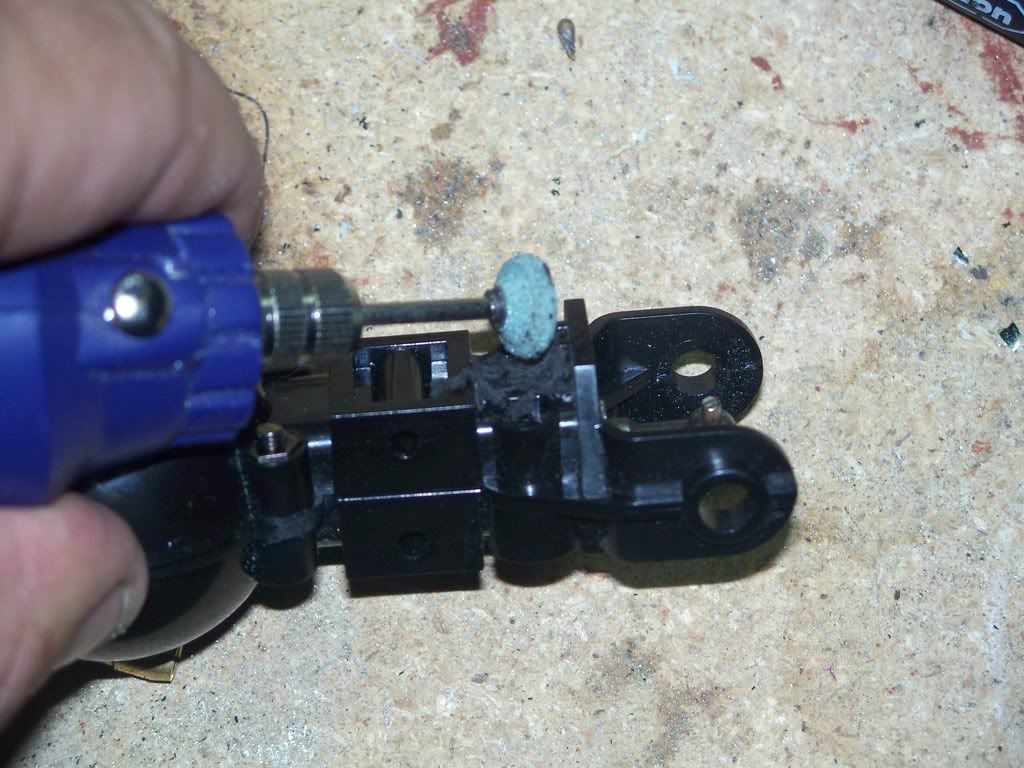 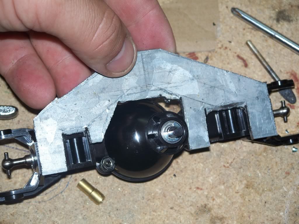 After the rough cut - I started to slowly take a little off here and there to ultimately get it fitting within the axle. When I say slow - I mean slow. In order to get it just to this point, I think I went through at least one hack saw blade. the last thing I wanted to do was to make another rought cut. Recall - this metal is "VERY" strong and tough. I'm sure it's perfect for this type of application but what a pain in the rear to cut! 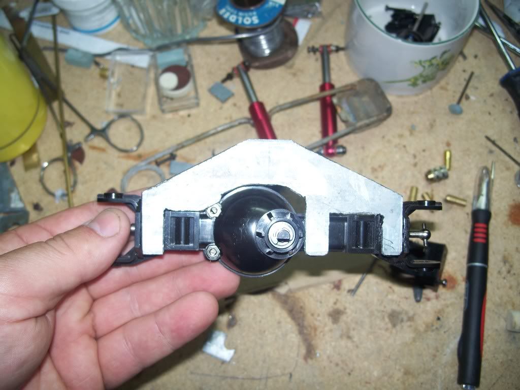 Now that the basic fit was there - I drilled a couple holes and tried to see if all this work would pay off. Hey! it did:-P I used the truck bed mounts as the brackets for the track bars and will do the same for the center bracket. It was a relief to see those bolt right up without having to do anything else to the die cut or the axle. 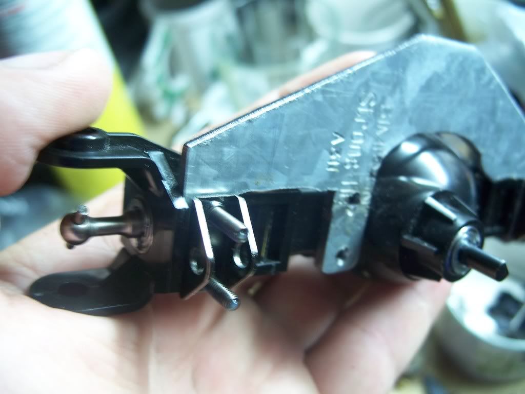 Today - I added the thrid center bracket and jjust test bolted it to the rear. Nice fit! I grabbed a couple of modified shocks to throw on it and will use those for the final build as they are adjustable and I'm not quite sure how this will all work out after it's finished. I picked up some stock threaded rod and a couple cuplinks (I think they're called). Roughly measured them out - cut - and rigged it together. As long as I was at it - I cut down the bracket a bit more to make it look more scale and not like a board - and since the other side of the grinder has a polisher - decided to polish up the metal. I was a bit suprised at how much galvanized steel polishes out 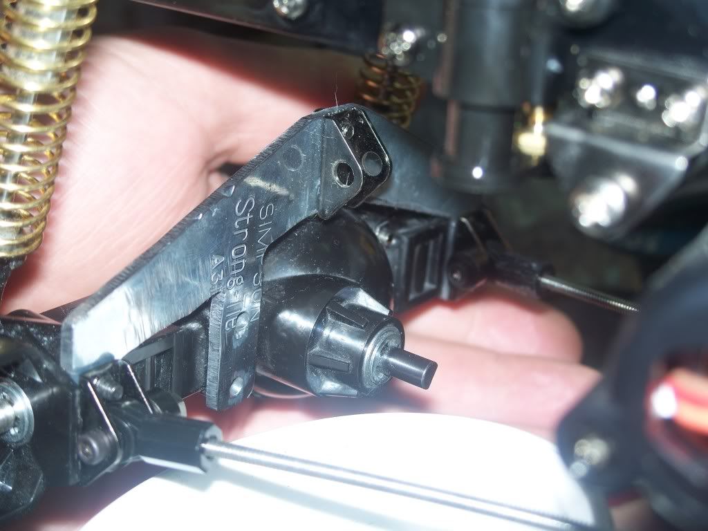 What I'll do later with the attaching rods is to use a series of aluminum tubes and consecutive sizes to build up some strength and bulk so they look more like a scale set of rods. 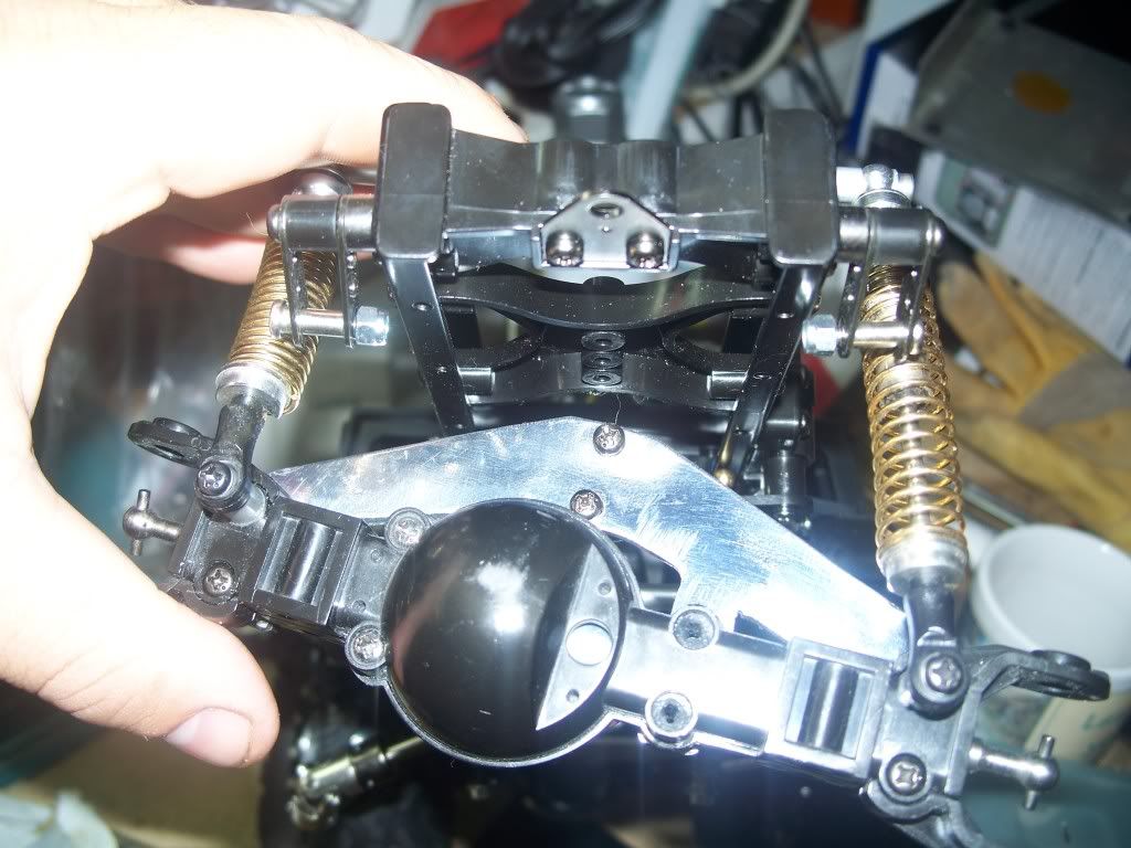 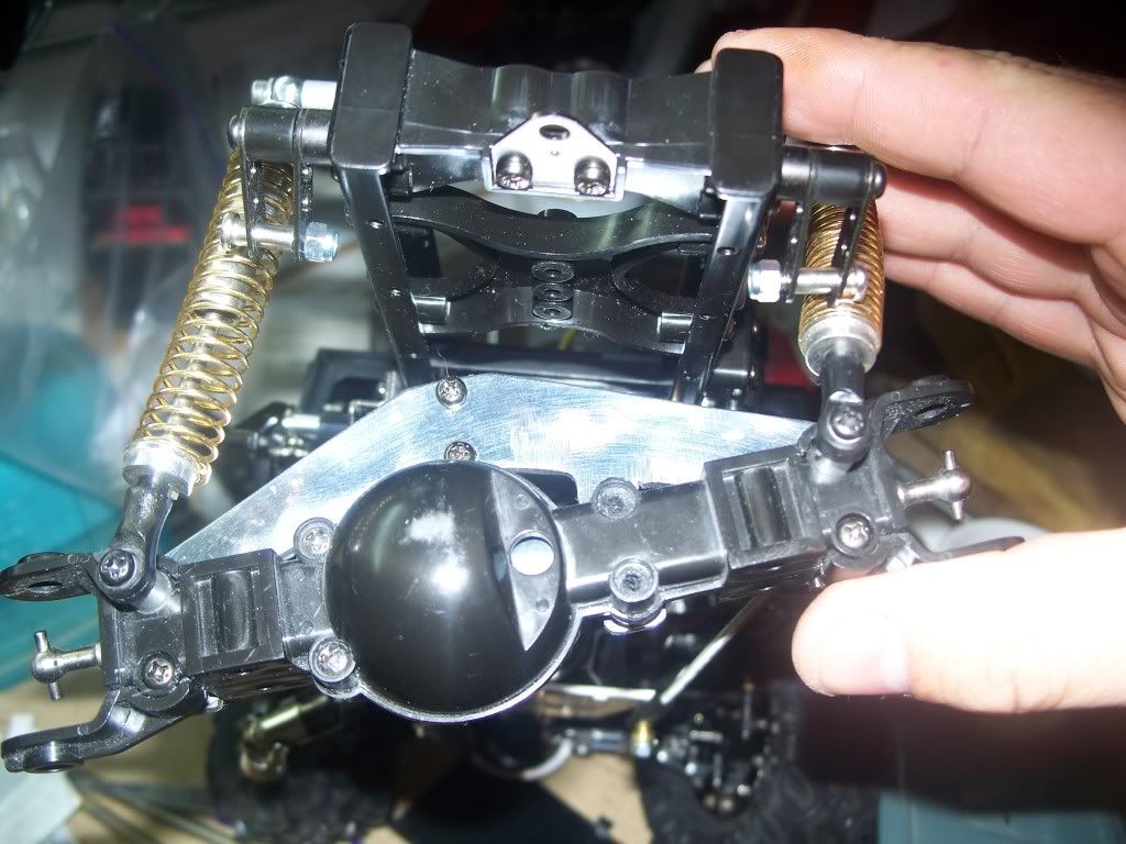 I can see already there's a bit more travel with the rear AND the "just so happens" way I cut it - helps fit just right under the truck frame when it's swayed to each extreme at the top of the bracket. I got lucky. Since that's just about done, I'm ready to move on to the grill which is nearly built. Last edited by FodigoDave; 10-18-2008 at 08:34 PM. Reason: duplicate photos added |
|
| |
|
10-18-2008, 09:32 PM
| #11 |
| RCC Addict  Join Date: Feb 2008 Location: Nevada
Posts: 1,267
|
wow! great brazing skills, love the Roof Rack, very clean I can't wait till i start brazing, looks like a blast |
|
| |
|
10-18-2008, 09:46 PM
| #12 |
| RCC Addict  Join Date: Mar 2007 Location: Penngrove
Posts: 1,809
|
looks realy good, nice fab skills on that roof rack what shocks are those in the rear? |
|
| |
|
10-19-2008, 08:21 AM
| #13 |
| Quarry Creeper Join Date: Sep 2008 Location: Petaluma
Posts: 282
|
Thanks guys. This was my first attempt at brazing. My first attempts were the top and bottom bars of the roof rack. In a couple of those pics - you'll see I used probably an entire brazing rod just to close two joints. But - after a few times at it - you end up getting the hang of it. I used a MAPP torch and "Brazing" rods (pack of three without flux). An important key in brazing is to make sure you rough sand the joint a little to remove any debris and coatings the metal may have to keep is shiny and then heating it to a molten red glow. A light touch with brazing rod and it's just about like soldering - only a lot stronger. If you don't pull the brazing rod out of the joint before removing heat - it will get stuck. Not worries of that happens, a snip with wire cutters will release it if you had the perfect weld and then just take a dremmel hand grinder to smoothen out the rough edges or extra brazing material left behind. After the roof rack was basically done, I pushed on it a few times to simulate a roll-over in various places to see how strong teh joints were and to see where the roof rack might fail. I found it might bend just a little where the light bar protection is on top but certainly wont break (Unless roll-overs become a habit I guess). I "think" heating the metal also weakens the original tensil strength but after each brazing weld, I quinched it in cool water. I was hoping that would limit the strength lost from heating. Not sure if I may have made it worse or not by doing that but I recall "Quencing" from my old school days when they talked about heating metal to make swords and would quench them in cow dung. Not that I wanted to use the "same" method here so cool WATER worked just fine. It also allowed me to work faster seeing I could touch it sooner for the next weld and besides - cow dung wasn't available. |
|
| |
|
10-19-2008, 02:46 PM
| #14 |
| Rock Stacker Join Date: Apr 2007 Location: Lake elsinore
Posts: 55
|
very nice i like your rack and axle truss |
|
| |
|
10-20-2008, 11:58 AM
| #15 |
| Quarry Creeper Join Date: Sep 2008 Location: Petaluma
Posts: 282
|
I SAW A f350 DRIVING DOWN THE STREET WITH A TOP AND BOTTOM BILLET GRILL. and of course, had to have it on my truck. Inspiration is found everywhere. After looing high and low and about 100 pics of other trucks, I found a guy that built a billet grill (kinda) on his truck using some "styrene." I've never heard of it so a google search revealed it's used in CD's. I thought about taking one of those useless AOL CD's that get sent to the house (every so often) and use a cheese grader to make some consecutive groove lines to simulate the lines in a billet grill. Then I happend to walk past the hobby shop near my area and stopped in to see if I could find some "scale" items to put in the roof rack (see above). I FOUND STYRENE! What a COOL bunch of plastic stuff. Like a sheet of plastic with the grooves already there ans perfectly straight - other sheets had diamond plate stamp, some "brick" stamped...and on and on. I found 2 pieces that "might" work as the groves were small on one sheet and bigger on the other. After sizing both up to the grill, I decided to go with the larger grooved piece. 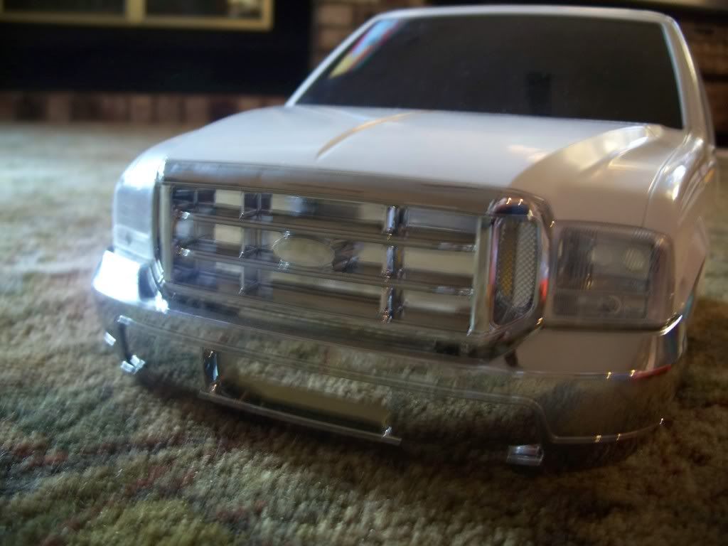 After cutting the styrene down to size to fit over the bottom hole in the grill, I later found some tacky "chrome colored" thin sheet of metal. This stuff is so thin, it's like a really thin sheet of aluminum foil (which might have worked better (but oh well)). I placed the chrome paper over the styrene and pushed down like "gold leafing". Nothing exciting here - just-do-it. Then placed it over the hole in the grill and glued it down. Pretty simple! 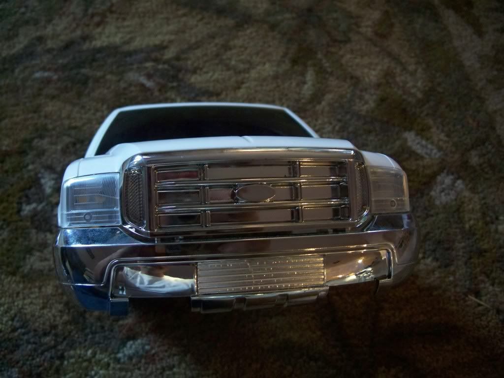 WOW _ COOL! An instant totally bitchen upgrade. 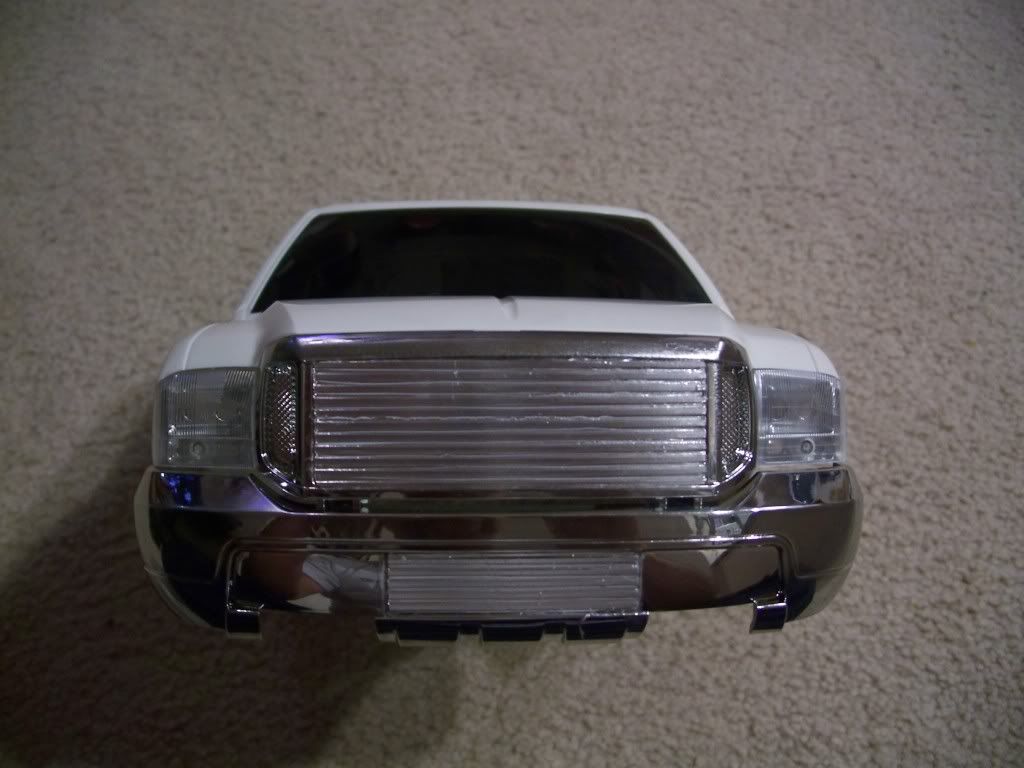 The upper grill was done the same way but took a bit longer for the glue to dry so I held it in place for about 10 minutes before releasing tension and then taped it to hold it over night seeing there's an arch to the front of the grill. I still have yet to place the "Ford" logo on the grill and paint the valleys of the styrene black. 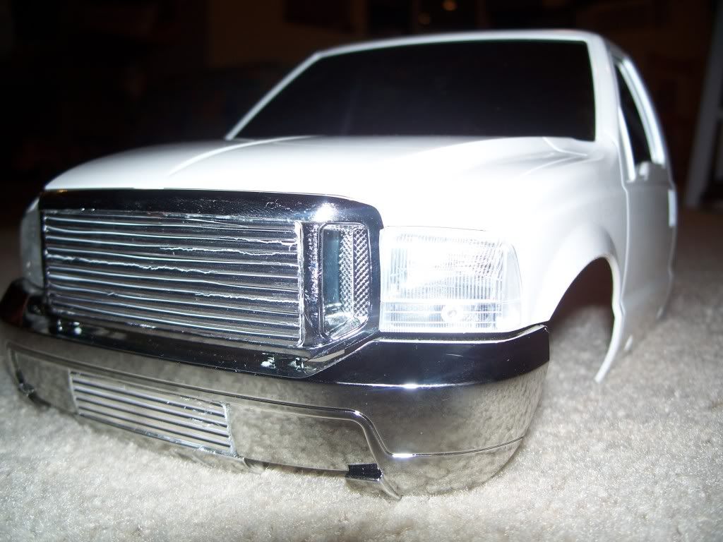 Those little white "squiggly" lines are the styrene showing through where the thin metal sheeting tore from pushing it down into the grooves. Those will go away when the black paint comes in and will leave nothing but the billet portion of the grill visable. Those that didn't tear, were given an exacto knife split so the top of the styrene edges got completely covered and the valley of the groove was exposed to take the paint. Last edited by FodigoDave; 10-20-2008 at 01:57 PM. Reason: typos galore |
|
| |
|
10-21-2008, 04:17 PM
| #16 |
| Rock Stacker Join Date: Oct 2008 Location: OC
Posts: 50
|
great build, do you plan on using a bed or will it be "backhalfed" ?
|
|
| |
|
10-22-2008, 04:01 PM
| #17 |
| Quarry Creeper Join Date: Sep 2008 Location: Petaluma
Posts: 282
|
In a couple days I'll have pictures (big ones of course) of the bed build. I plan on making a soft top but can't find a fabric place around that has a material "scale" enough. Any ideas on a material would be helpful !! The brass tube construction is just about built but I still need to run a few more supporting brackets at the base to get it to attach to the bottom of the bed. Thanks for asking - I'll certainly get on some pics soon for ya. Finished or not. But you'll get the main idea. The specific idea is to hide the components to the Multi-function unit but it will all tie together nicely as the roof rack is housing the lights - versus the stock roll bar. I've also got a front bumper I'm working on (brass too - solid core) that should be able to withstand the toughest hit. Of course - when it's closer to done - it'll be posted. The tires were finished the other day (RC4WD bead locks). |
|
| |
|
10-25-2008, 09:58 PM
| #18 |
| Quarry Creeper Join Date: Sep 2008 Location: Petaluma
Posts: 282
|
QUESTION, I'm working on the rear shock towers and was wondering about placement. Anyone have any idea why some have decided to mount the shocks at an angle versus straight up and down? Does that allow for more travel? I'm courious.... |
|
| |
|
10-25-2008, 11:39 PM
| #19 | |
| I wanna be Dave Join Date: Jul 2006 Location: Moscow Mills MO
Posts: 2,204
| Quote:
Nice build you got goin | |
|
| |
|
11-04-2008, 12:58 PM
| #20 |
| Quarry Creeper Join Date: Sep 2008 Location: Petaluma
Posts: 282
|
that's good info - I'll most likely try to build a bracket to house the rear shocks a bit differently. Here's the update to the front bumper. Only the main idea was constructed using a solid core brass rod with a brass sleeve for just a touch of thickness. Funny - the lights just bolted right up. 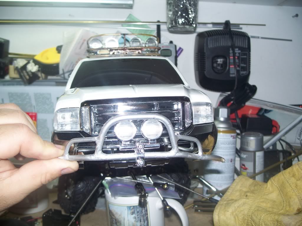 I'll still need to do a lot mroe work on the bumper. Wasn't planning on a wnch at this time so didn't account for any room in those regards. As for the soft top. More Brass ! (all this brass should certainly give me a bit of extra grip - the stuffs heavy) Anyway - here's the progress being made. 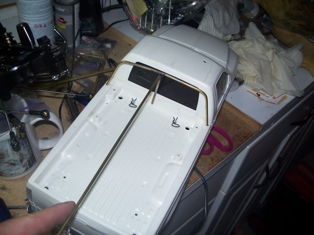 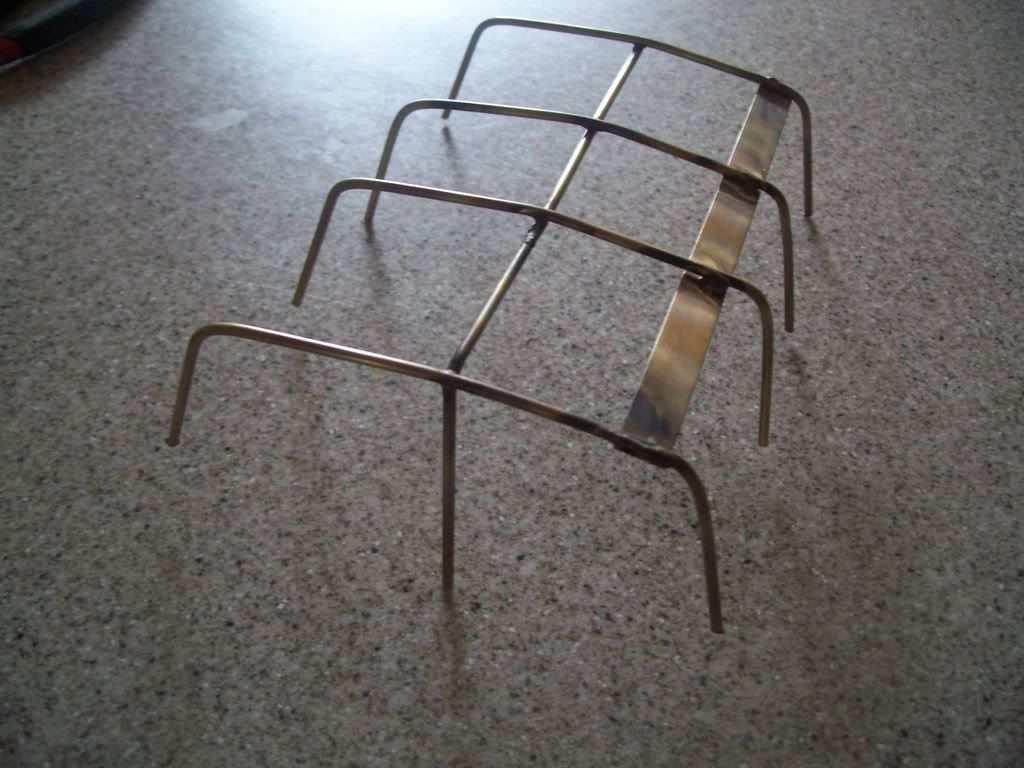 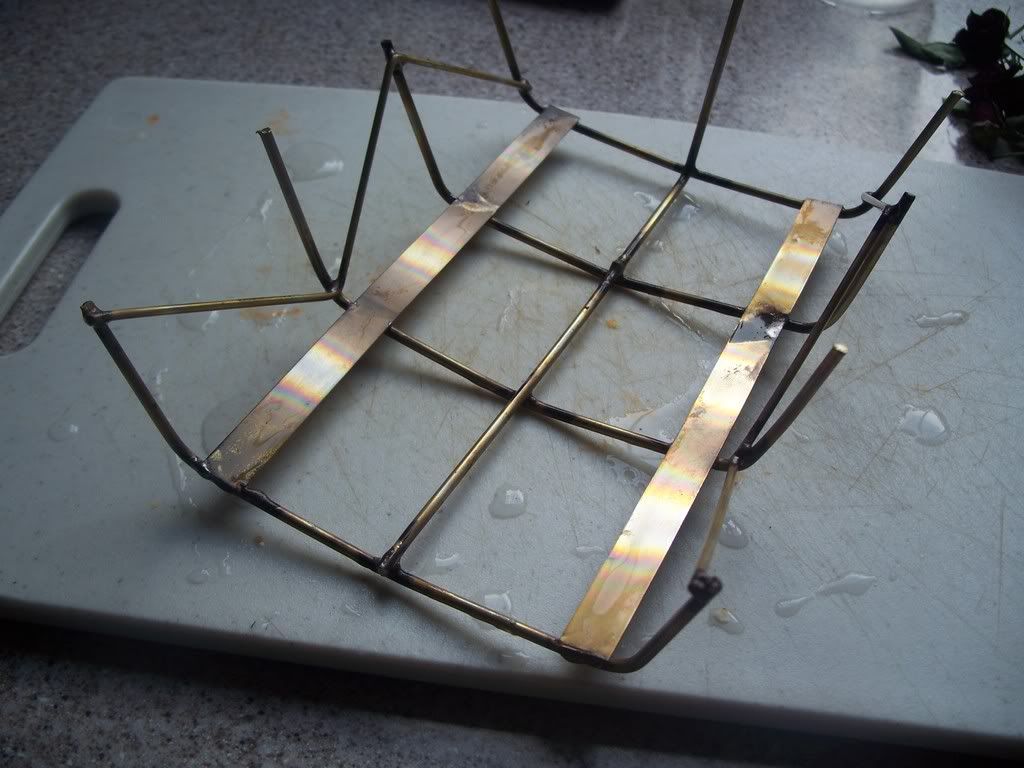 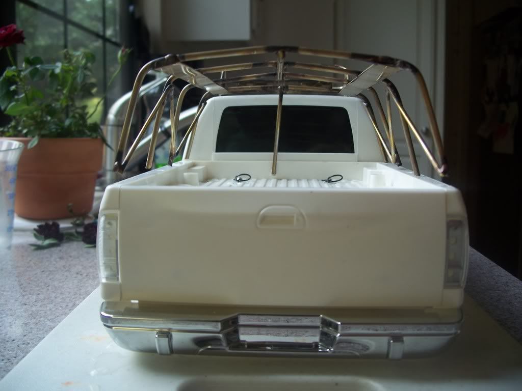 |
|
| |
|
| |


 Linear Mode


