| |
 02-18-2009, 11:08 PM
| #1 |
| Rock Crawler Join Date: Jun 2006 Location: Wisconsin
Posts: 570
|
I finally picked up a Tamiya High-Lift. When they first came out, I saw myself ending up with one eventually, but it's taken a while. Since I have so many other project trucks and crawlers, I promised myself to build this thing stock and enjoy it.....but stock is not a word in my vocabulary. I did manage to assemble it and run a few packs through it before deciding to rebuild it. At first, I didn't feel I would enjoy the truck that much, but after some run time outside, and indoors, the suspension really softened up, I started digging the 3 speed transmission, and it became fun to run. Despite me not expecting much out of the leaf spring suspension, the truck has gotten pretty capable, but not quite capable enough for me. Here are some photos of it, box stock, less an upgrade to full ball bearings, and a Novak 55T motor. 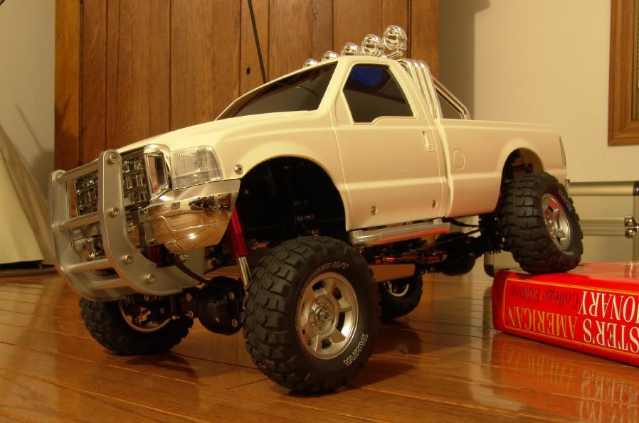 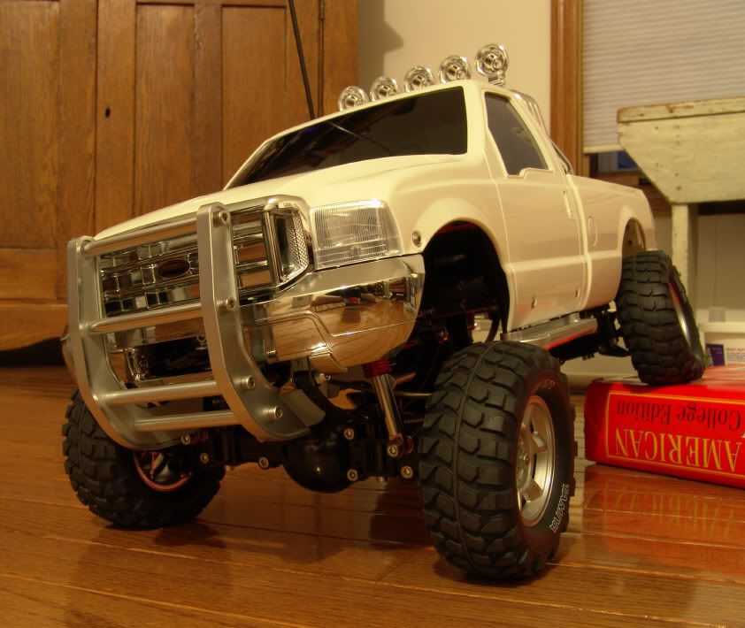 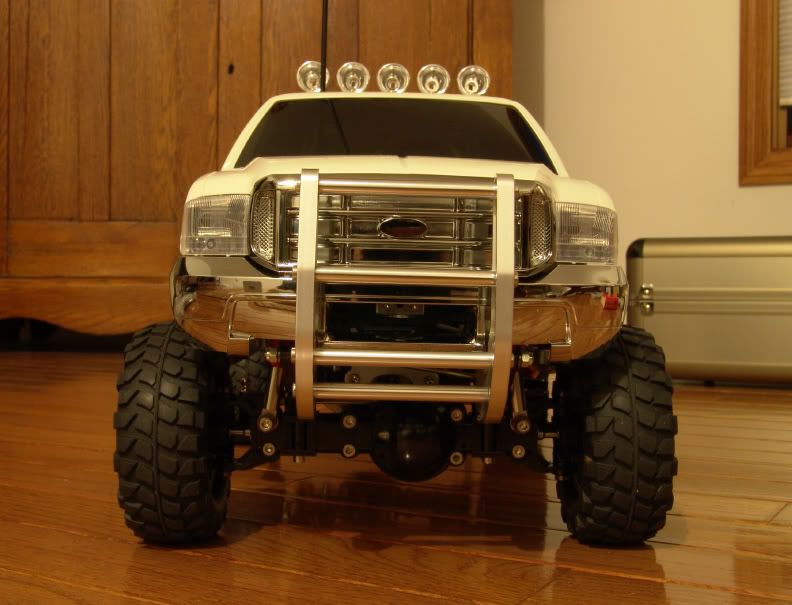 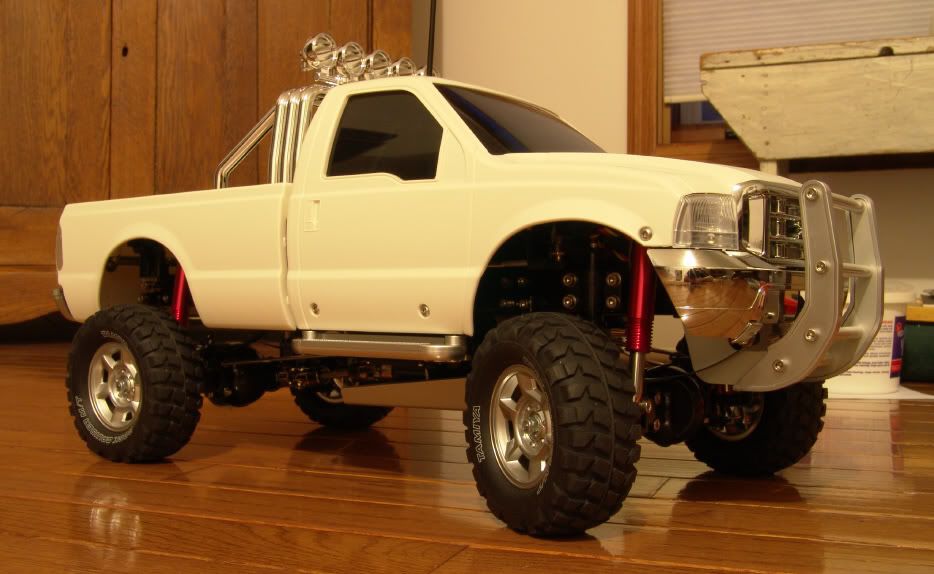 And of course, a money shot! Not bad articulation at all. Yes, the rear wheel is lifting, but not by much! 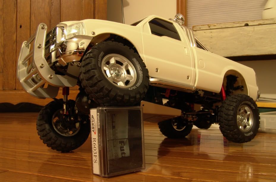 I didn't bother painting the body, but I do have some ideas. I can't spray any color this time of year anyway. No paint booth and it's way to cold outside. Crawling this truck around outside on the frozen snow banks, and indoors over piles of books and other objects, I came to realize, like many other before me, that the ground clearance is a weakness of the High-Lift. I was still pretty impressed with the performance, none the less. Originally, thoughts of 4 linking the axles popped in my head, but I now plan on keeping the leaf springs. It wouldn't be a High-Lift without them. It's simple, scale, and it works better then I expected! And so, yesterday I tore the truck back down. My dad laughed at me and said 'yeah right' when I told him I was going to build it stock. Well, I did build it stock, but it's not staying that way. The first order of business was to raise the transmission. I did some searching and found a couple threads to help point me in the right directions. Then I went to work. I whipped up some transmission mounts and settled on a 7/8" (23mm) transmission lift. I thought about going higher, but decided not to. I didn't want to push my luck with the driveshaft angles. I fabbed the mounts out of some aluminum and notched them so thickness of the frame would be accounted for. That way I wouldn't need to run spacers or stand offs to tie them into the transmission mounts. 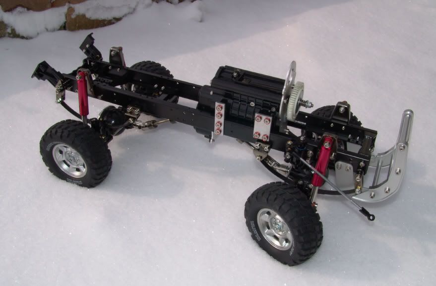 Figures we'd get a bunch more snow on the day I tear my truck down! I should have ran it one more time, but oh well. I'm sure we'll get more. For the final photo, here is the center ground clearance, after the efforts. The driveshafts fit just fine and they don't bind at the universal joints at all. It seems I settled on a very good height. The suspension will settle, further reducing the angles, once the truck is back together. That's all for now, but a lot more work needs to be done yet. I'll share more tomorrow. I already have some other things in the works! |

|  |
| Sponsored Links | |
| | |
|
02-18-2009, 11:12 PM
| #2 |
| Newbie Join Date: Jan 2009 Location: Detroit
Posts: 37
|
keep it up Nice looking rig so far
|
|
| |
|
02-19-2009, 03:00 AM
| #3 |
| Quarry Creeper Join Date: Sep 2008 Location: Petaluma
Posts: 282
|
Looks Good! Keep up the great work. On mine- I noticed that little tire lifting like a dog lifting his leg on a fire hydrant when the fronts bumped up a notch or two. Yours really seemed to loosen up a lot. maybe I had too many leafs in. Good luck - I know its going to turn out great. How did you keep it so clean in all that FRESH snow? |
|
| |
|
02-19-2009, 10:06 AM
| #4 |
| Rock Crawler Join Date: Jun 2006 Location: Wisconsin
Posts: 570
|
Thanks for the comments guys. Dave, it was pretty easy to keep the High-Lift clean and free of snow, simply because the thing was undriveable at the point I snapped those photos. I had pretty much tore the truck down to the frame. When I stepped outside to get some brighter pictures, under natural light, I was wishing I wouldn't have broken the truck down until after I got some run time. Oh well. Okay, so challenge one was raising the transmission. Now it's time for challenge two. Here's the skinny on the situation. I know raising the transmission would normally mean lifting the body to clear the motor. As it is, stock, the motor pratically hits the windshield. I don't want to lift the body, if I don't have to. A guy starts to get a non-scale look, after a point, and I like the way the High-Lift sits right now, as far as height goes. So that leaves me with relocating the motor. I've seen a kit, made by a German company called Bamatech. It mounts the motor to the side of the transmission and uses a belt drive to transmit power. This kit looks nice, but it's not my thing. Rather then hang the motor off to the side, I will be mounting it between the frame rails, just in front of the transmission, where the shift servo sits. The motor will be under the spur gear, rather then on top. I should have no problem keeping the body height stock, by doing this. So, what I am in need of is a remote motor mount plate. I made a copy of the Tamiya manual and took some measurements. Thankfully, Tamiya has full sized drawings, in the manual, of the transmission plates. I took the basic dimensions and drilled out the holes I would need, as well as the adjustable motor slot. 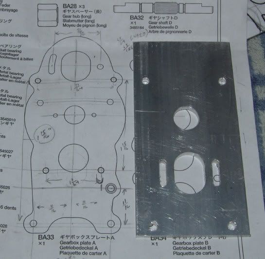 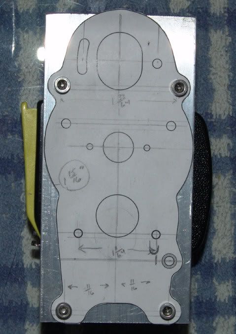 I still have some finish work to do on the plate, but this will give a really good idea of how it will look, when it's finished. 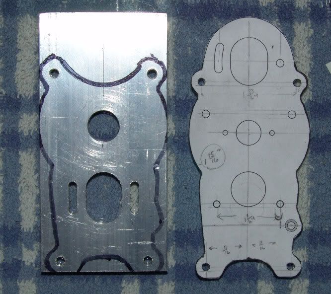 The 4 holes in the corners match the holes in the transmission end plate. These will tie into the transmission to secure the plate, and I will offset the remote motor plate with some spacers / stand offs to clear the spur gear. It will basically be sitting in front of the spur gear. The center hole is a clearance hole for the slipper clutch adjustment nut. If all goes well, I'll have the plate finished tonight and I'll share more photos then! Last edited by Espeefan; 02-19-2009 at 11:53 AM. |
|
| |
|
02-20-2009, 10:11 AM
| #5 |
| Rock Crawler Join Date: Jun 2006 Location: Wisconsin
Posts: 570
|
I've got a little more work done on my High-Lift, so here is an update! My remote motor mount plate is now finished. It turned out great. I couldn't be happier with it. I changed the profile, a little, to make a little more classy and streamlined. If you compare the above photos, with the marker drawn on it, you'll see what I mean.  Here it is with the motor mounted to it..... 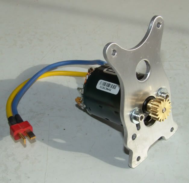 And then, the new motor plate mounted to the transmission. 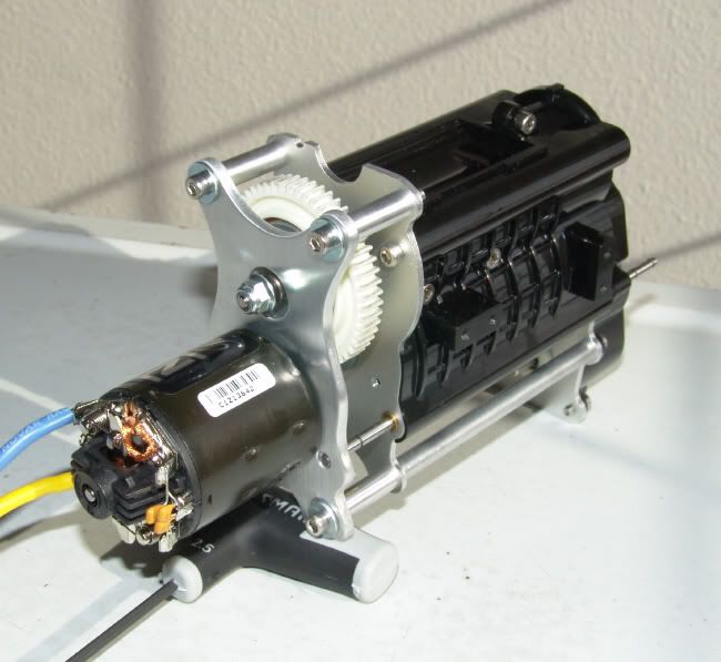 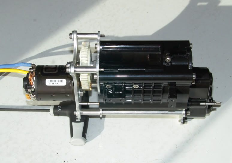 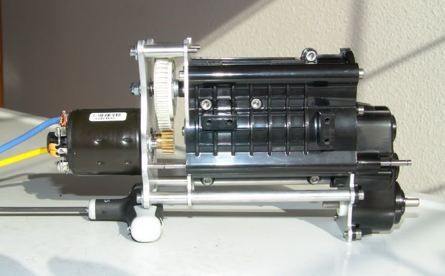 It should help get back, and maybe even improve the High-Lift's center of gravity. With a little more weight transfer to the front end, it may also be a better crawler. The motor hangs over the front axle now. 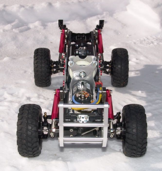 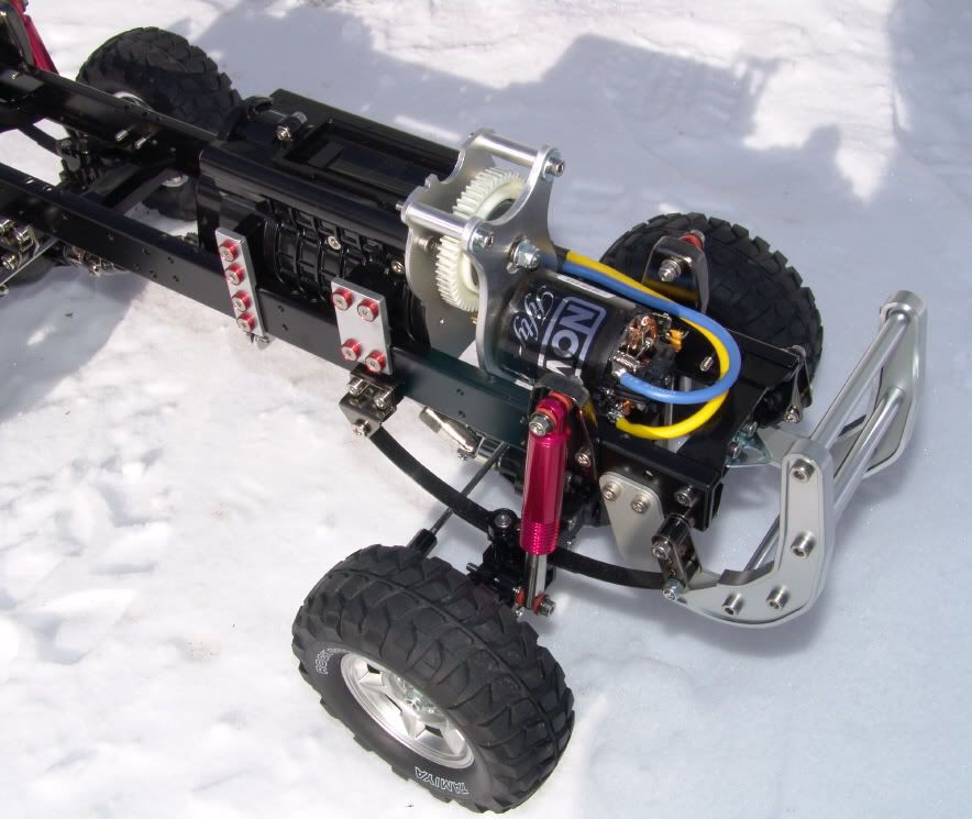 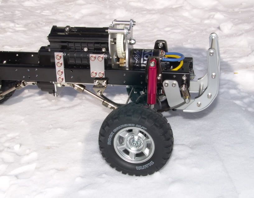 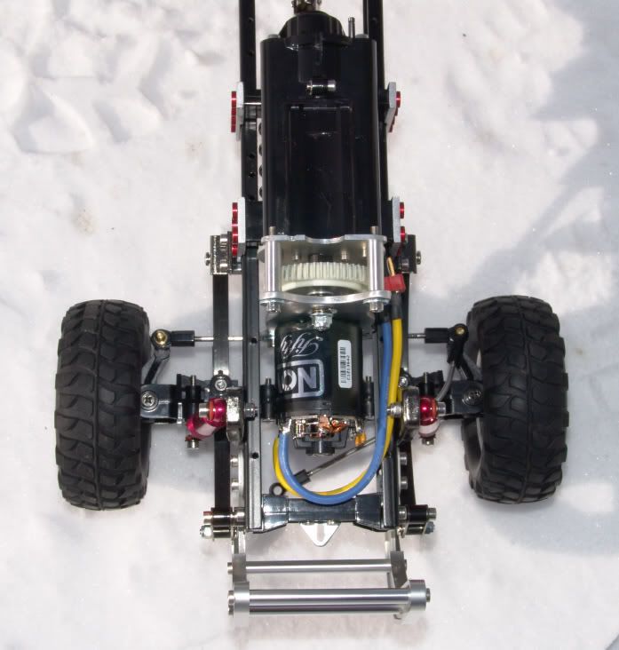 Just a couple more over all chassis shots now. I like how well the motor tucks in between the chassis rails. Almost like I knew what I was doing! 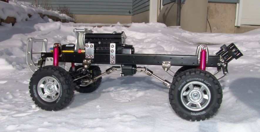 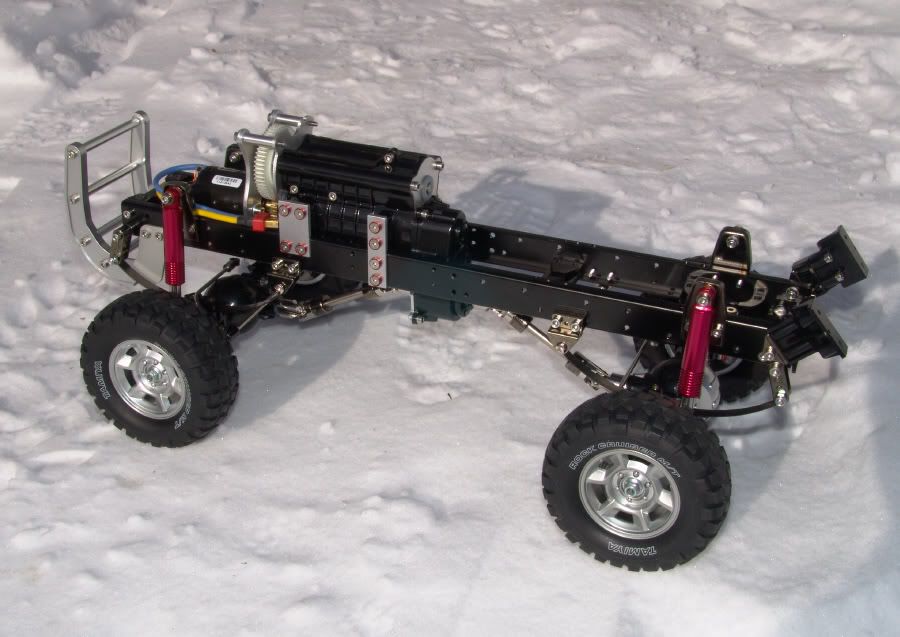 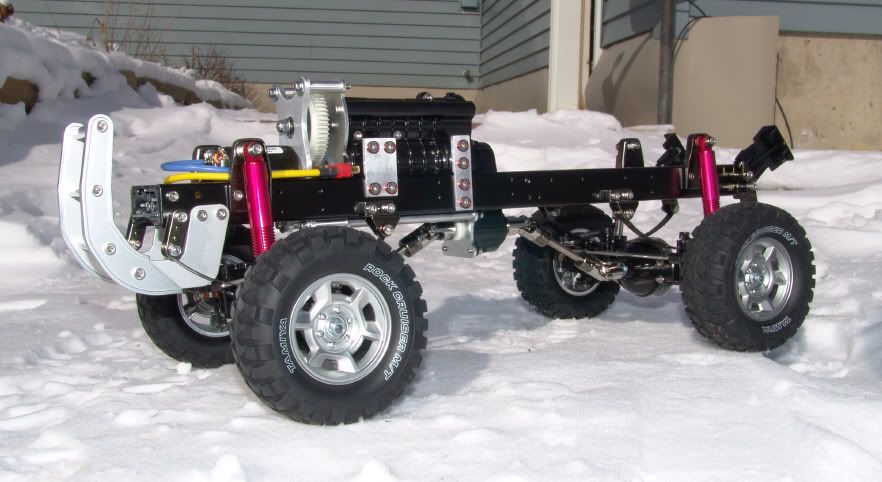 Let me know what you think! Thanks for looking. Last edited by Espeefan; 02-21-2009 at 05:05 PM. |
|
| |
|
02-20-2009, 10:38 AM
| #6 |
| Newbie Join Date: Jun 2008 Location: columbus
Posts: 32
|
Looks good. Are you ging to run the shift servo from the rear now or is there still enough room in the front.
|
|
| |
|
02-20-2009, 10:44 AM
| #7 |
| Rock Crawler Join Date: Jun 2006 Location: Wisconsin
Posts: 570
|
Crawlerbug, thanks. Yes, my current plan is to relocate the shift servo to the rear of the transmission. Since the shift fork shaft protrudes out the rear of the transmission, that seems to be the most likely option.
|
|
| |
|
02-21-2009, 12:24 PM
| #8 |
| Quarry Creeper Join Date: Sep 2008 Location: Petaluma
Posts: 282
|
VERY CREATIVE ESPeefan, I like it! Now I see what your talking about with the mounting forward idea. I was thining you might be using another shaft extension but I see thats not the case. If you relocate the shift servo to the rear, that means your going to use the stock battery compartment? Now need to answer that one, I'll be wtching... Great job... |
|
| |
|
02-21-2009, 02:00 PM
| #9 |
| I wanna be Dave Join Date: Aug 2007 Location: santa monica
Posts: 3,687
|
very clever idea relocating the motor there. Also very nice craftsmanship on the plates, especially the new motor plate. Very professional looking.
|
|
| |
|
02-21-2009, 05:09 PM
| #10 |
| Rock Crawler Join Date: Jun 2006 Location: Wisconsin
Posts: 570
|
Dave, thanks for the kind words! I changed the battery location early on, with my truck. It's been mounted on the rear frame rails, under the box, like 90% of the other guys running High-Lifts. I am 95% sure that I will be able to maintain that location, even with a shifting servo mounted behind the trans. Pablo, thanks! I wasn't sure how well I would be able to fab up the new motor plate, but it turned out really nice. It's probably the most ambitious modification I've done in a long time. |
|
| |
|
03-07-2009, 11:57 AM
| #11 |
| Rock Crawler Join Date: Jun 2006 Location: Wisconsin
Posts: 570
|
Hi guys! It's been a busy couple of weeks and I've got a few updates to show for my High-Lift. I managed to devise a plan to over come a couple more challenges. First, I wasn't all that impressed with the stock Tamiya steering set-up. I had wanted to do a front mounted servo, with simplified linkage, right from the start. The multi-linked bellcrank set-up had a fair amount of slack in it, which I didn't care for, so I came up with a new solution. Since my motor is now where the servos would normally be, I had to fab up a separate servo mount and relocate the steering servo to the side of the chassis frame rail. 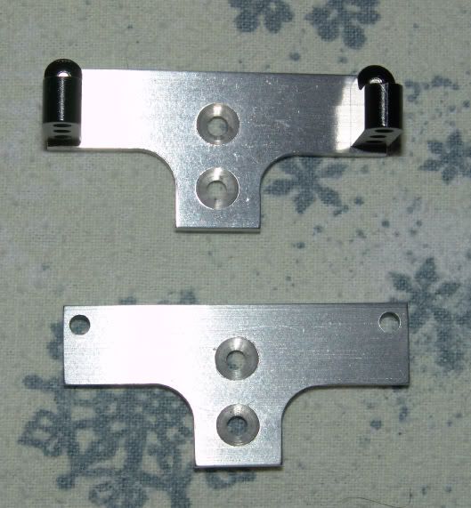 Here's the new plate I made, along with some aftermarket servo stand offs. These are just Axial AX-10 pieces, and they work excellent because they are so simple and compact. Oh, and I figured since I was going through the trouble of making these plates, I'd make two because a guy could always use a little 4 wheel steering action, especially with locked differentials.  The new servo mounts bolt right up the frame rail, but space is extremely tight up front. My transmission lift bracket was getting in the way, just a touch, so I bolted the new servo mount to the chassis with some spacers. The offset is enough so that the new mount is somewhat layered over the corner of the trans bracket. Knowing what I know now, I may remake these parts in the future and combine the servo mount with the trans bracket, in one piece, but for now, this works very well. 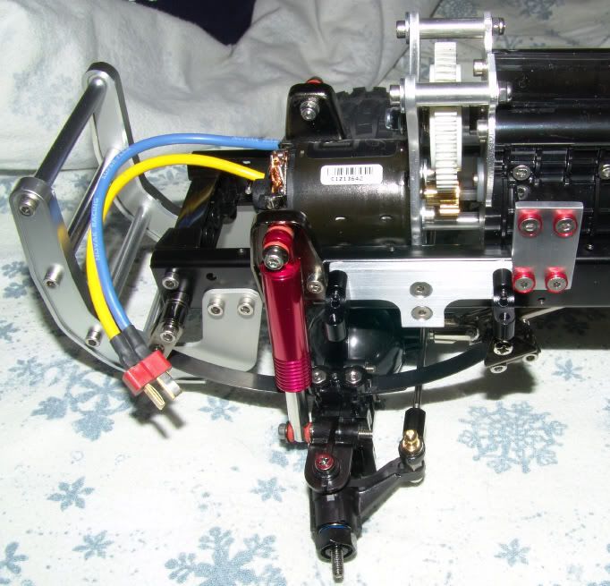 Here's a picture with the servo mounted up. 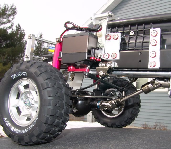 To transfer the power, I whipped up a quick steering link with a piece of carbon fiber tube. I simply JB Welded some 3mm studs into the ends and then added the Traxxas rod ends. I will probably be making a few more of these. I can't have the stock knuckle links anymore, since they don't match my drag link! 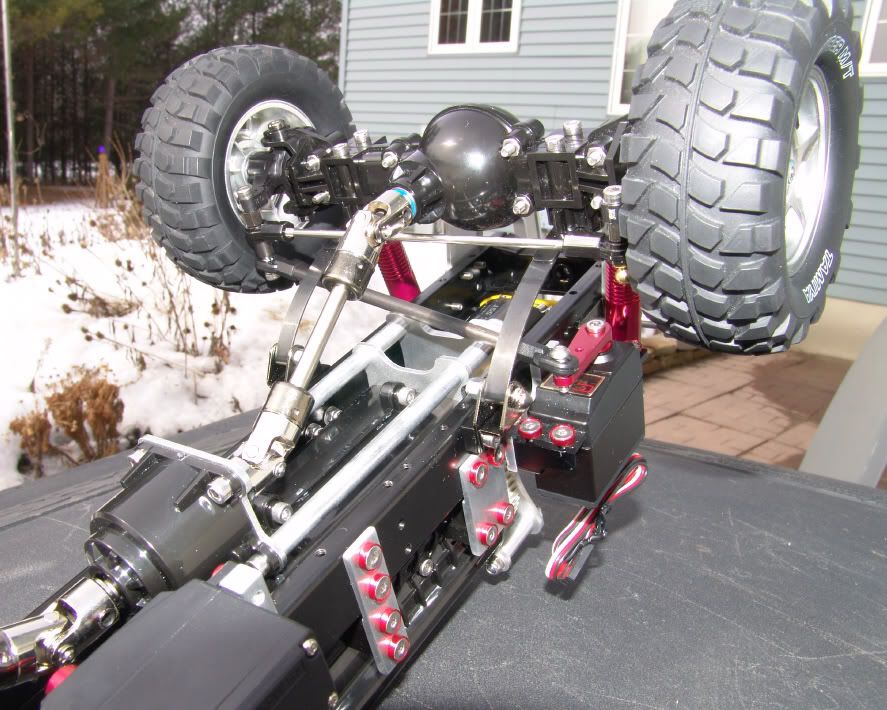 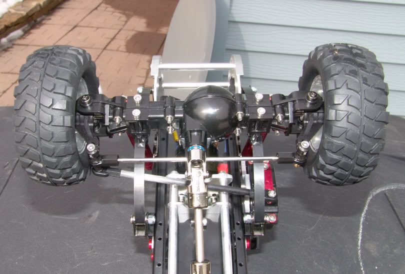 Here's a good head on view of the new set-up. I was very pleased that it all fit together well and I have absolutely no bump steer what so ever, even under full compression! 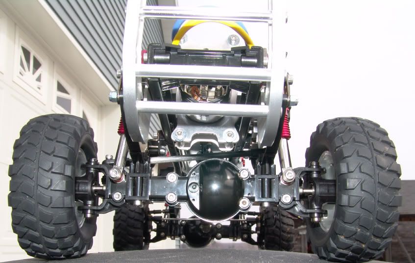 Here's a photo with some articulation thrown into the mix. My carbon fiber drag link does touch the stand offs of my remote motor mount plate, if I physically push the suspension far enough by hand, but this is with the suspension pretty much bottomed out (and springs flat) and I don't think the truck has ever articulated that much, under any conditions, nor do I think it ever will. Though it looks close in the above photo, there is no rubbing and the angle makes it look tighter then it really is. I will keep an eye on this when I start driving it. It's funny because if I would have raised my transmission 1" instead of 7/8", there probably would be no chance of interferance at all. I doubt I will have any issues with the present set-up, but it's one of those little things that I know about, and being somewhat of a perfectionist, I usually can't leave well enough alone. 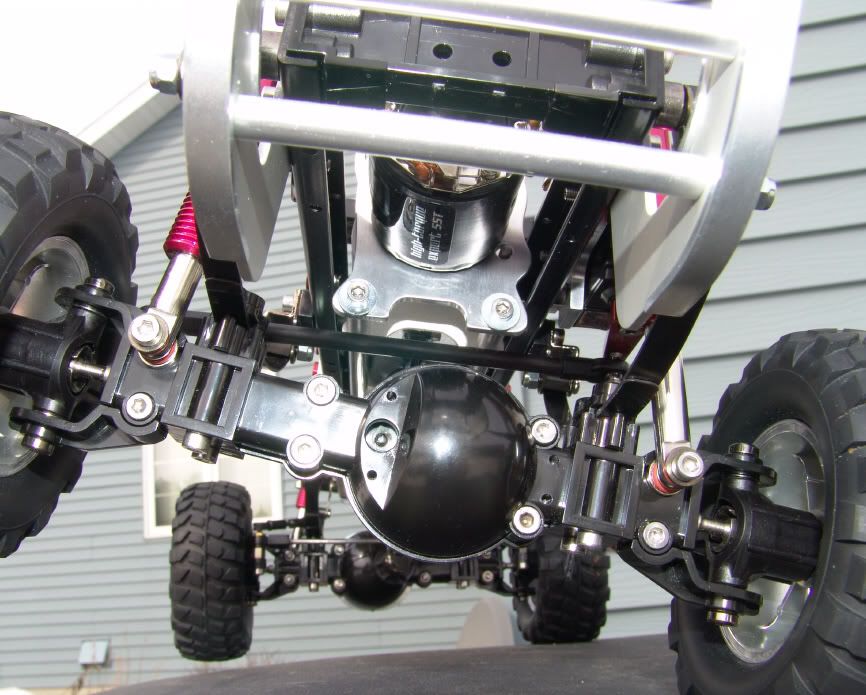 I'm also planning on a pan hard bar to keep the axle from walking around, and probably a traction bar to prevent an axle wrap-up. The other thing I needed to work out was my shifting servo's new location. This turned out to be relatively easy to solve. I just made a really simple mount and bolted the servo to the side of the chassis, just behind the transmission. 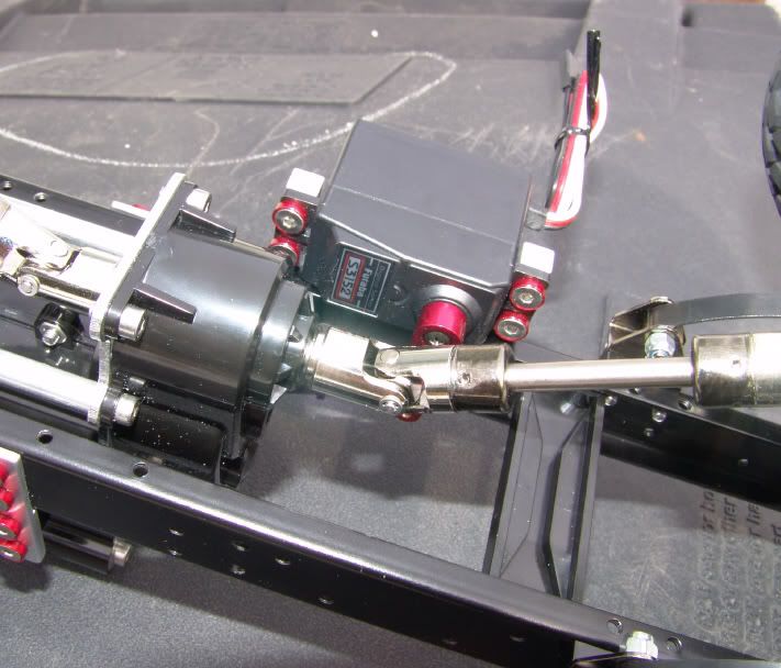 It was nice of Tamiya to include a long enough shift rod. I was able to throw the stock parts together and make use of tail end of the rod. It works perfect like this. 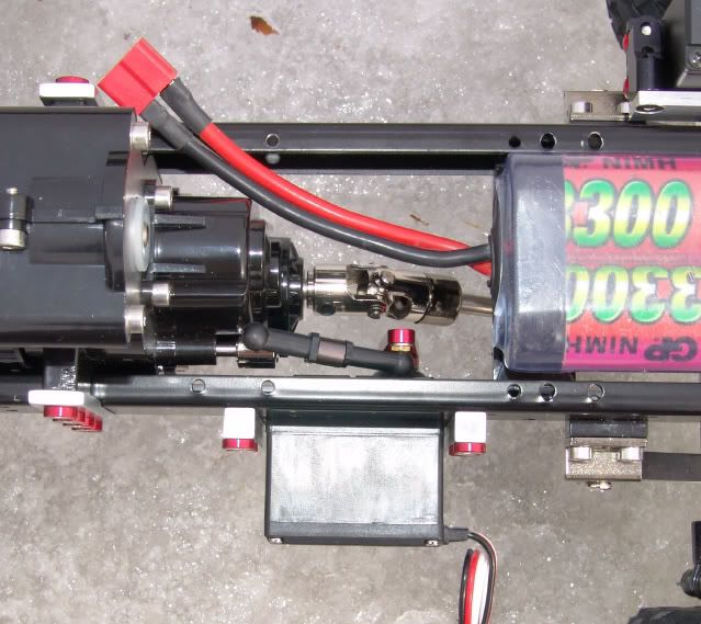 It all fits together nicely, and there is still plenty of space for my battery pack to sit in between the frame rails, as I planned. 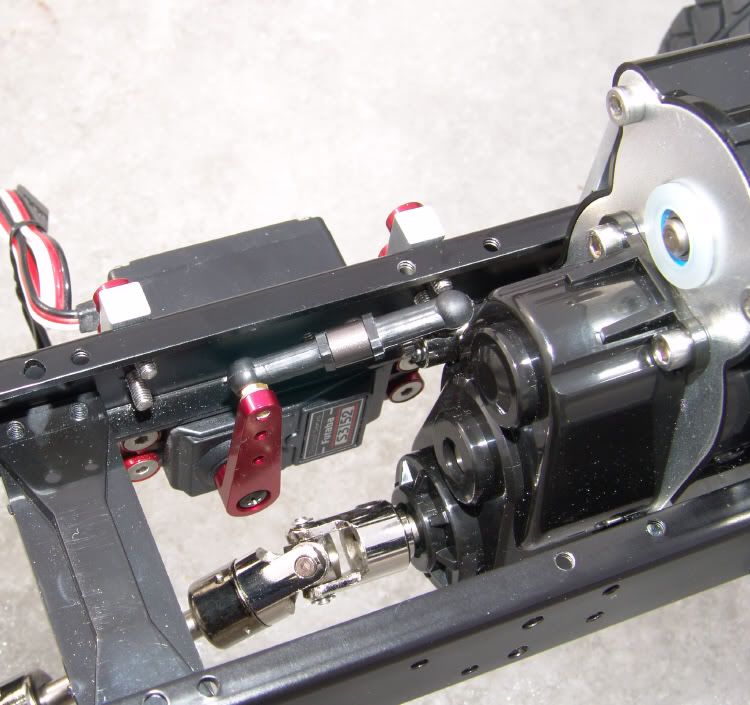 I souped up the stock shift linkage by tapping the rod ends for a new 3mm stud. I had problems with the original 2mm threaded rod. My servo could easily pull the rod ends right off the rod because they fit so loose. I also added a bushing to stiffen it up. The last couple photos are of the chassis, as it now sits over all. 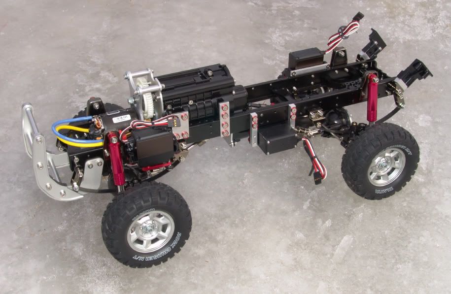 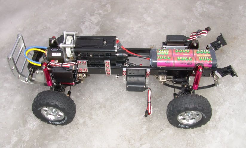 I just about have everything worked out now. I've also started hacking the cab floor to fit the chassis. I found out that I will need to raise the body now to clear the transmission, but not by much. Only about a 1/4", which is hardly anything. The larger tires I will be running should fit better with a slight body lift anyway. Stock tires rubbed sometimes, so anything larger would definitely be rubbing too. Things will work out for the better this way. I like it when a plan comes together! For the most, I think the chassis mods are done. Up next - body work?? I'll have to see how that goes. I may not attempt it, as I'm no body man. |
|
| |
|
03-07-2009, 12:14 PM
| #12 |
| I wanna be Dave  Join Date: May 2006 Location: HONDURAS...ROCK HEAVEN
Posts: 5,076
|
Very nice work , i would like to do the front motor mount mod, looks very interesting, would like to know how the hl reacts under hard braking.
|
|
| |
|
03-07-2009, 08:56 PM
| #13 |
| Rock Crawler Join Date: Jun 2006 Location: Wisconsin
Posts: 570
|
Thanks cartronicshn. I'm not sure braking will be much different then before. The weight is still in the same place, for the most part. Perhaps slightly heavier torward the front, but running a battery pack under the box proves that the truck is close to a 55/45 weight distribution. It almost balances under the transfer case. It's definitely more stable with the motor located lower. I haven't driven the truck since the first go around of mods, but I am really getting the itch. Tomorrow is calling for a lot of snow!
|
|
| |
|
03-18-2009, 11:34 AM
| #14 |
| Rock Crawler Join Date: Jun 2006 Location: Wisconsin
Posts: 570
|
Hi guys, a small update today! Since my chassis is pretty well finished, less a few finishing touches, I've decided to turn my attention to the F-350 body. I wanted to do something a little more, in order to dress the truck up and make it stand out from a crowd. I'm not a body man by any means, but I have worked with styrene a bit in the past. I had been toying with idea of adding a cowl induction hood, or a hood with dual air scoops. I decided that the cowl hood would be a bit easier for a novice, like myself to tackle, so I gave it a shot today. I've already got a bit of time invested in this cowl already, having roughed out the basic shape, separately from the truck a few days earlier. I finally got the nerve to glue it to the hood. At worst, I figured I would be out $25 bucks for new body, if it proved to be a failure. Here are some photos. 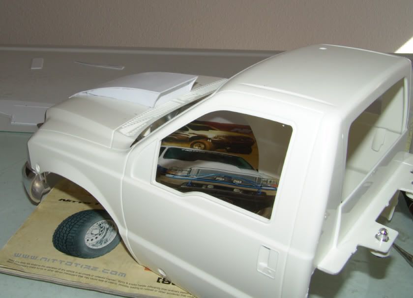 Eventually I will make a screen or something similar to set off the cowl on the backside. 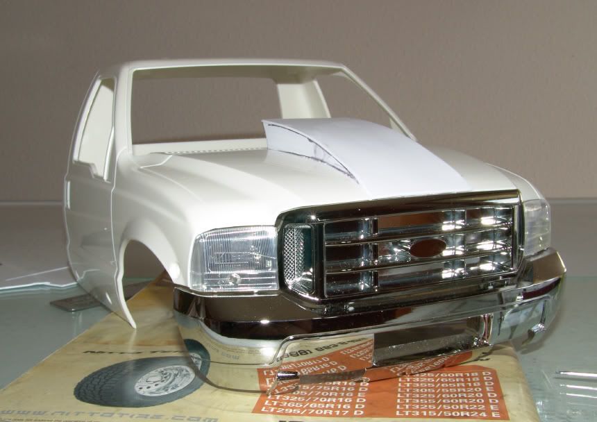 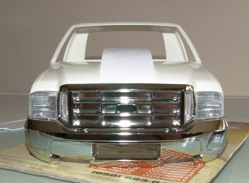 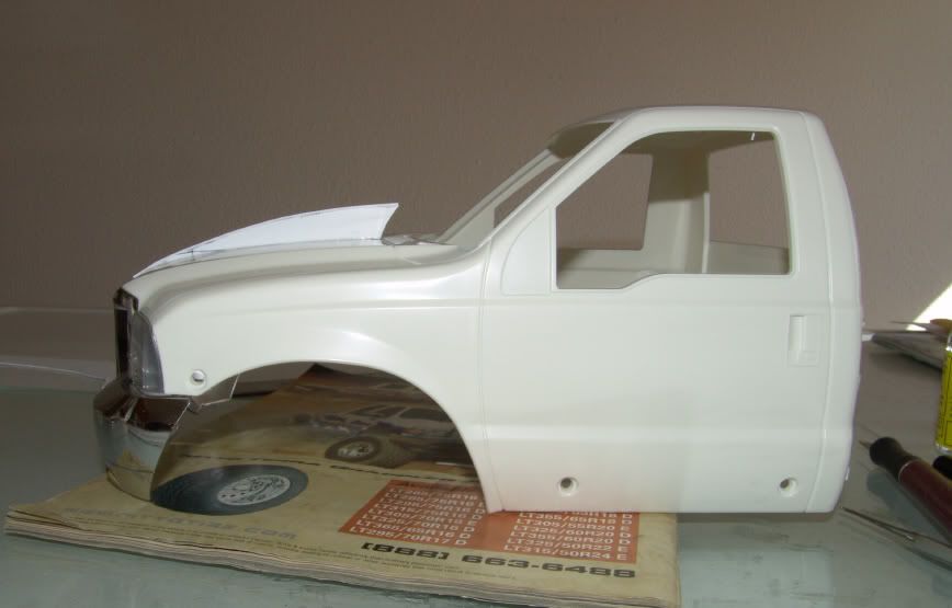 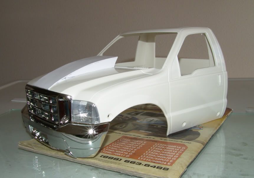 Don't mind the marker lines on the cowl. Those are just some marks I made early on, as I was fitting the profile to the stock hood. There is still more work to be done. I want the cowl to be molded to the hood and have a rounded profile at the edges. Smooth and flowing, with a radius. I am thinking about the ways I can pull that off. I don't want this to be all body filler. I learned early on that body filler cracks way to easily and I'd rather use some styrene to make it solid. Well, that's it for now. Let me know what you think! My photobucket account sent me a warning about getting close to exceeding the bandwidth for this month (already?!?), so I don't know how long these photos will last, but hopefully you can see them! |
|
| |
|
04-02-2009, 11:16 AM
| #15 |
| Rock Crawler Join Date: Jun 2006 Location: Wisconsin
Posts: 570
|
Work on the High-Lift has been slowly coming along. I messed up the cowl hood and had to re-do it. I was trying to mold the cowl it into the stock hood, with some thin styrene, when things went wrong and I ended up with some huge crinckles in the styrene pieces. I ended up tearing it all off, sanding the hood down bare again, and starting over. The nice thing is that working with styrene is kind of like metal work. If you take to much off, you can always put it back on and sand it to shape again. Or completely remove something and start over. I thought I would have to buy a new cab, but it sanded down so nice, I could barely tell I had a mis-hap to begin with. So I just got done whipping up an identical cowl for the hood. I will begin molding it to the stock hood once more, but this time with body filler. It should go a lot smoother, I hope. Other little things done - the body ride height had to be raised a little to 3/8" more. The cab floor was modified to fit around the transmission too. I also made some carbon fiber toe links for the steering knuckles to better match the drag links I already made, and last of all, I have been playing with the off road lights and decided I wanted three of them mounted to the brush guard. 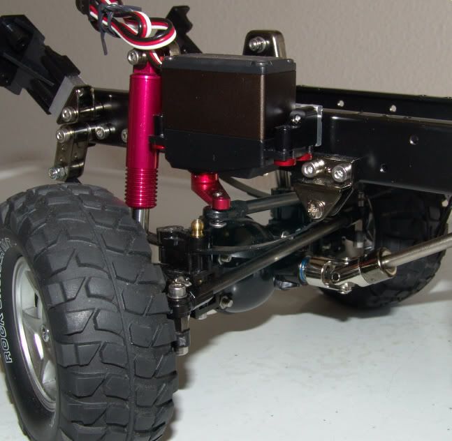 Rear carbon toe links. 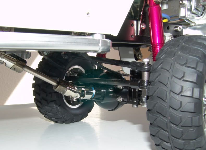 Front toe link. It looks tight, but works just fine, with no rubbing at all. 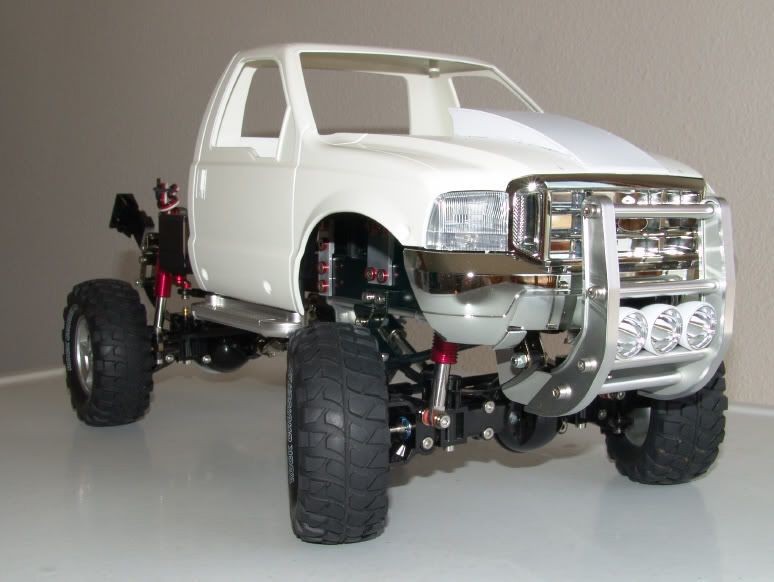 New ride height (not overly tall - new tires on the way, which will fill the gap of the fender anyway). 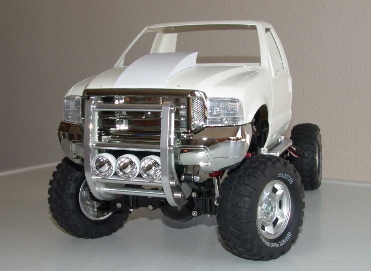 And, three off road lights mounted to the brush guard. I figure I may not run the stock roll bar, but I wanted to keep the off road lights, so I found a new home for them. I love working lights, so the roll bar may also stay. This thing will really light up the terrian once the LEDs are wired. |
|
| |
|
04-02-2009, 11:39 AM
| #16 |
| RCC Addict Join Date: Jun 2008 Location: Monroe, NC
Posts: 1,547
|
Great work on this thing so far. I would only suggest one thing... maybe making the cowl wider? Also, what type of camera do you use? The pictures look great. Justin |
|
| |
|
04-02-2009, 11:49 AM
| #17 |
| Rock Crawler Join Date: Jun 2006 Location: Wisconsin
Posts: 570
|
Thanks Justin. The cowl width will increase, once I get it properly molded to the stock hood. In other words, the sharp 90 degree edges of the cowl will get blended into the stock hood, with a radius of some kind, so that it all looks like one piece. I could see it picking up another 1/2" or so of width from that process. My camera is an out of production Sony F-828. It does take good pictures, but I also enjoy photography myself, so I know enough to be dangerous. |
|
| |
|
04-07-2009, 11:18 AM
| #18 |
| Rock Crawler Join Date: Jun 2006 Location: Wisconsin
Posts: 570
|
I know this isn't a huge update, but it is a little progress, none the less. I am still working (still fighting) with the cowl induction hood, but the good news is it is improving. I already screwed up once, so this time I gave some thought to how I could make it work. I ended up making some filler pieces out of styrene and glued them to the cowl sides, with a gentle slope. It didn't turn out to bad. I am happy with the look and they way it fit, for the most part. I still need to do more blending to really make it look nice, and that will come with time. For now, just more sanding and shaping. Possibily a filler piece to bridge the seams an give me a little more material work blend. I refused to use body putty to mold the cowl's edges, so this explains some of the pains. When this thing is done, it'll be much stronger then putty and it won't have the potential to crack, which I've had in the past. 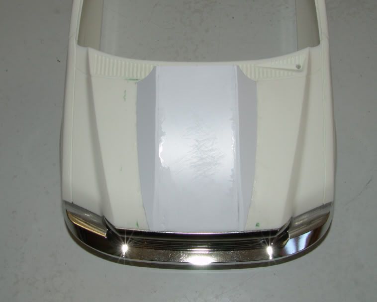 Don't mind the ugly seams. They'll disappear with some more sanding. The edges aren't quite flush yet. 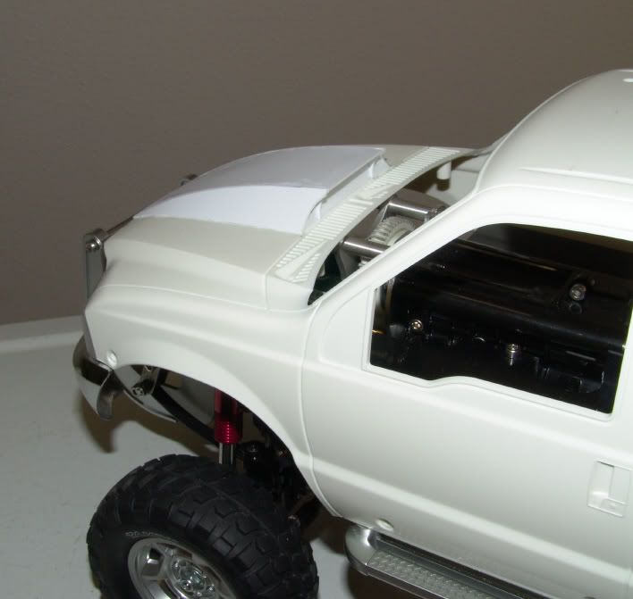 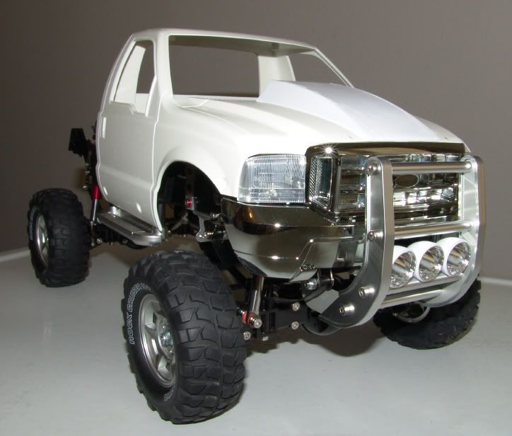 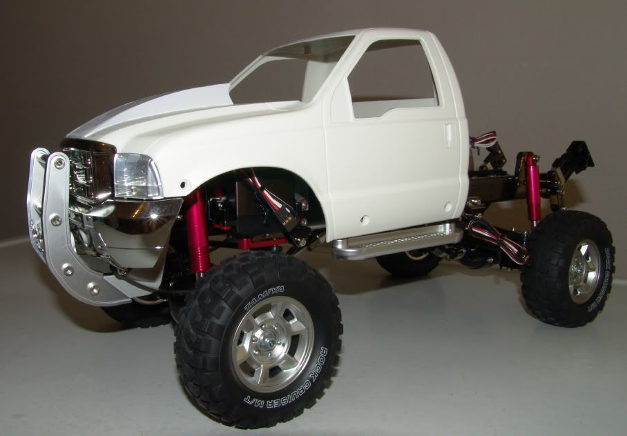 |
|
| |
|
04-07-2009, 11:34 AM
| #19 |
| RCC Addict Join Date: Jun 2008 Location: Monroe, NC
Posts: 1,547
|
Looks great. |
|
| |
|
04-07-2009, 12:40 PM
| #20 |
| I wanna be Dave Join Date: May 2006 Location: HONDURAS...ROCK HEAVEN
Posts: 5,076
|
That's it, i am boxing my hl up and sending it to you |
|
| |
 |
| |


 Linear Mode


