| |
| |||||||
 |
| | LinkBack | Thread Tools | Display Modes |
 10-15-2011, 10:30 AM
| #1 |
| Pebble Pounder Join Date: Sep 2009 Location: Canada
Posts: 156
|
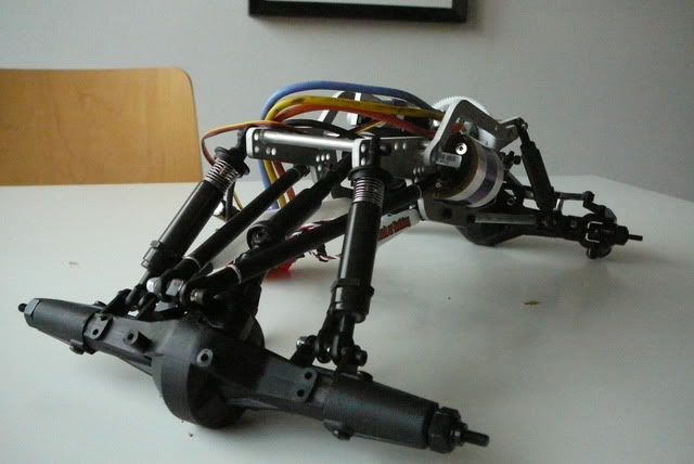
so I've finished Axial Mod 2.0 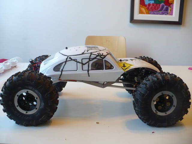 Modded Axial and I already want to start on mod 3.0. With the current chassis complete, I was able to take a step back and look at the overall design and some issues were obvious and some not so obvious. I want to lower the overall profile which means I'll need to change the rod ends on my tmaxx shocks and I want a more cab forward weight distribution so I've elongated the rear of the chassis and pulled the front in a bit. The rest of the cab forward movement will be done by shortening the front links and lengthening the rear as per Gunnar's comments. The old chassis plates are in blue and the new is in red. I've overlaid them to show where the changes have occured. 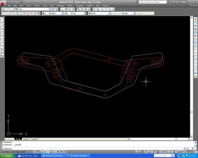 and the sketchup model. The new one in red and the old (current) in green 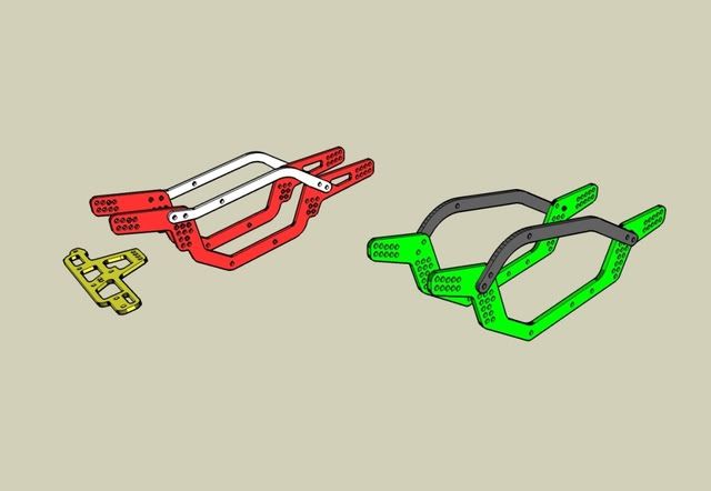 I've designed a front plate that will clear the BTA steering setup better than my modified plate. Plus, the GCM 4 link mount I used on the front is getting in the way of the battery placement. I want to move the GCM to the rear and keep the D-link for another project. |

|  |
| Sponsored Links | |
| | |
|
10-15-2011, 11:48 AM
| #2 |
| Quarry Creeper Join Date: Oct 2010 Location: Ukraine
Posts: 400
|
Neverending story I wish i could see the action some day. Anyway that is a nice idea with a weight distribution. Have luck |
|
| |
|
10-18-2011, 04:43 PM
| #3 |
| I wanna be Dave Join Date: Aug 2004 Location: central VT
Posts: 2,300
|
Somehow I get the feeling your one of those weird perfectionist. But whatever, just keep the pics of homemade parts coming so the rest of us can have some inspiration too. And if you could somehow make a printable template with scale for that sweet BTA plate you'd have many grateful friends on here. |

| |
|
10-27-2011, 09:05 PM
| #4 |
| Pebble Pounder Join Date: Sep 2009 Location: Canada
Posts: 156
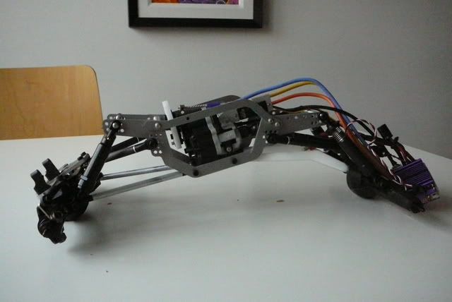
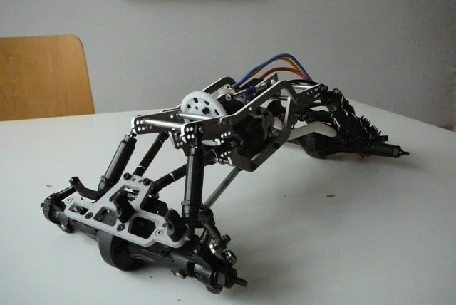
| 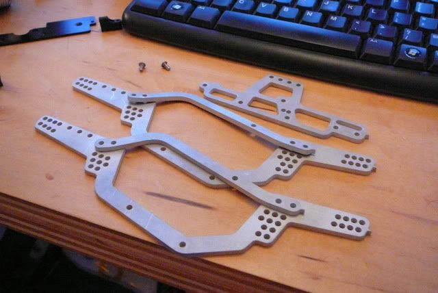   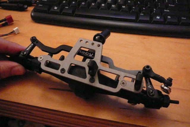 I designed the servo/battery plate so that I could mount the front links on top, or on the bottom and not interfere with the BTA linkage. 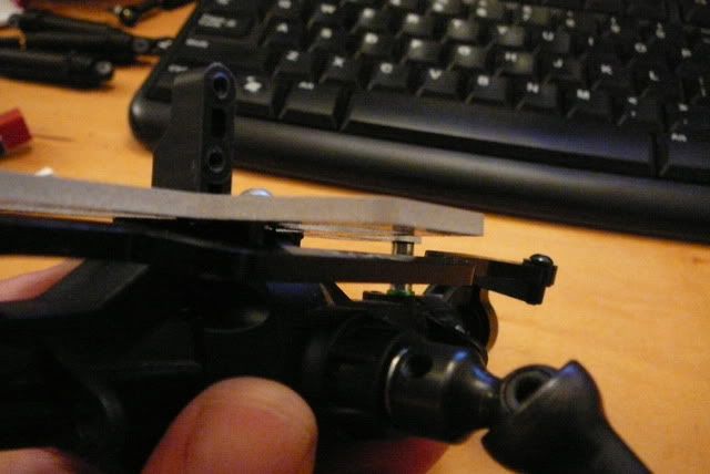 |
|
| |
|
10-28-2011, 07:26 AM
| #5 |
| Rock Crawler Join Date: Sep 2011 Location: truckee
Posts: 918
|
looks like its going to be a cool set up. can i ask where you got that spring lever thing on the dig? thanks
|
|
| |
|
10-28-2011, 07:31 AM
| #6 |
| Rock Crawler Join Date: Dec 2009 Location: Beaumont, Tx
Posts: 507
|
Dig lever looks home made from throttle/brake lever off a nitro car. I like your chassis. need another tester? That thing is sweet. |
|
| |
|
10-28-2011, 01:16 PM
| #7 | |
| Pebble Pounder Join Date: Sep 2009 Location: Canada
Posts: 156
| Quote:
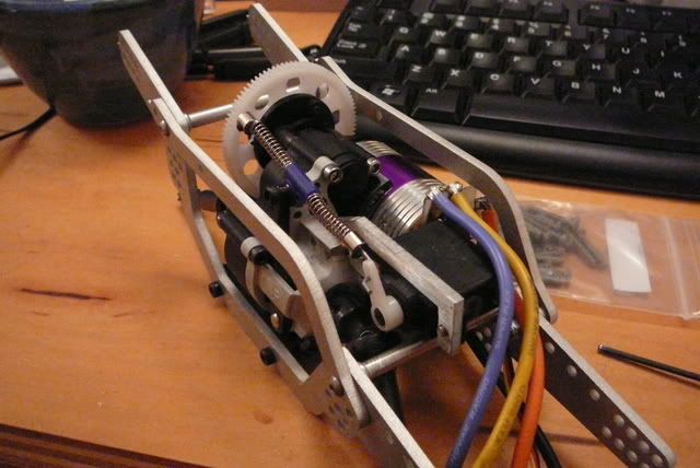
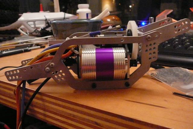
it works great with zero binding. it's also adjustible for tension. The servo is super cheap, produces 42oz of torque and has plastic gears. So far no issues but I am upgrading to a mirco savox servo (all metal gears) because I think I may have stripped a few teeth on the existing servo gears while working on it. | |
|
| |
|
10-29-2011, 07:31 AM
| #8 | |
| Rock Crawler Join Date: Sep 2011 Location: truckee
Posts: 918
| Quote:
| |
|
| |
|
10-29-2011, 01:49 PM
| #9 |
| Pebble Pounder Join Date: Sep 2009 Location: Canada
Posts: 156
|      |
|
| |
|
10-30-2011, 05:08 PM
| #10 |
| Pebble Pounder Join Date: Sep 2009 Location: Canada
Posts: 156
|
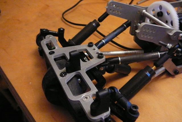
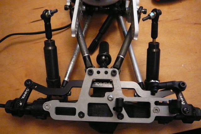
Anyone else have this issue? Once you torque down the screws holding your front or rear lower links to the skid you end up with cock-eyed screws. This happens because the holes are slightly larger than they need to be and the radius on the inside of the skid allows the rod end to rotate and end up behind the adjacent link. I've drawn red lines through the axis of the screws to show the skewed result. 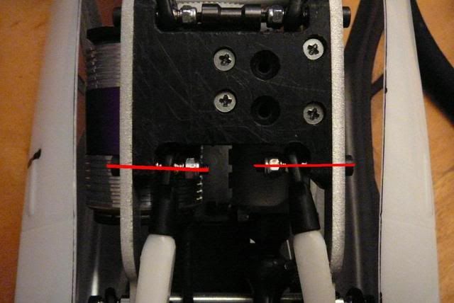 The fix is simple. I took two of the small threaded posts that came with my Axial BTA steering kit and threaded it on to the ends of each of the lower link mounting screws. This aligns everything as well as filling the gap left between the two links. Everything stays nice and tight. 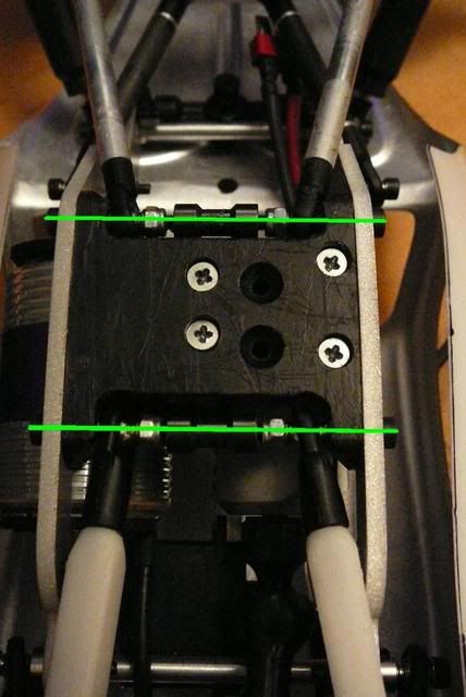  |
|
| |
|
10-30-2011, 05:50 PM
| #11 |
| Suck it up!   Join Date: Mar 2008 Location: Arkansas
Posts: 11,652
|
Looking good.  I've had that alignment problem too. Never did anything about it because it didn't really effect too much. That chassis kinda looks familiar... [IMG]  [/IMG] [/IMG]
|
|
| |
|
10-30-2011, 07:39 PM
| #12 | |
| Pebble Pounder Join Date: Sep 2009 Location: Canada
Posts: 156
| Quote:
the devil is in the details duuuuuuuude. | |
|
| |
|
10-30-2011, 07:51 PM
| #13 | |
| Suck it up! Join Date: Mar 2008 Location: Arkansas
Posts: 11,652
| Quote:
Certain Death comp rig! Details, schmetails. | |
|
| |
|
10-30-2011, 07:57 PM
| #14 |
| Pebble Pounder Join Date: Sep 2009 Location: Canada
Posts: 156
|
ohhh that's yours. Someone said that's a Canadian rig. Is this the case?
|
|
| |
|
10-30-2011, 08:00 PM
| #15 |
| Suck it up! Join Date: Mar 2008 Location: Arkansas
Posts: 11,652
|
Yup, the guy who designed it is from Canadia. Don't know if he still does it or not. I think there was a link in that thread for him...
|
|
| |
|
10-31-2011, 10:18 AM
| #16 |
| Pebble Pounder Join Date: Sep 2009 Location: Canada
Posts: 156
|
I found a thread with the chassis unobstructed with electronics. I can definitely see the similarities now. Certain Death comp chassis The hockey stick shape must be imprinted in every Canadians brain. |
|
| |
|
10-31-2011, 10:24 AM
| #17 | |
| Suck it up! Join Date: Mar 2008 Location: Arkansas
Posts: 11,652
| Quote:
| |
|
| |
|
11-01-2011, 08:00 PM
| #18 |
| Pebble Pounder Join Date: Sep 2009 Location: Canada
Posts: 156
|
My Savox servo came with a poor selection of servo horns, but I got to thinking I could make use of this 6 point one. The space for linkage up front is tight so I'm going to try some heavy gauge wire. There's no slop, it's not going to pop off the horn and when the wire eventually elongates the hole I've got 5 others to use. We'll see how well it holds up to the 416oz the savox puts out. 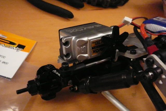 Last edited by Jessf; 11-01-2011 at 08:03 PM. |
|
| |
|
11-14-2011, 07:11 PM
| #19 |
| Pebble Pounder Join Date: Sep 2009 Location: Canada
Posts: 156
|
I'm currently waiting for my next iteration in the chassis and servo plate. I've "borrowed" some design ideas Certain Death chassis in order to gain more room for the upper links. I've also design some knuckle lock outs that I think will suit my driving style. I've been driving the current chassis at my local proving ground, an old stone constructed mill in Guelph. So far I'm pulling lines with this setup that I couldn't even consider with the old modded axial chassis mod.
|
|
| |
|
11-21-2011, 04:50 PM
| #20 |
| Pebble Pounder Join Date: Sep 2009 Location: Canada
Posts: 156
| got my new design back from the shop. I think this will be the last one. I've lowered the CG by roughly 5mm given myself some clearance for the rear upper links (I now understand the Certain death chassis better) and I've taken a chunk out of the front servo plate to allow for clearance on the swing of a larger servo horn. The knuckle weights are designed for the Axial high steer knuckles that came with the BTA kit, and they fit my 9mm shell casings filled with lead. With the added weight of the gunnar tubes up front I wasn't sure I needed much in the way of knuckle weights so I'm trying only 3 holes with the heaviest object at the very bottom. 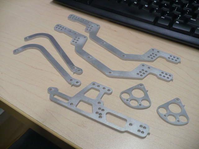 probably won't get a chance to put it all together for a few nights but I'm anxious to see how it crawls. |
|
| |
|
| |


 Linear Mode


