Go Back   RCCrawler Forums > RCCrawler General Tech > Electronics
Loading

Notices

Thread: Definitive wiring diagrams for BECs Rx Servos Motors etc.

Reply
 
LinkBack Thread Tools Display Modes
Old 05-31-2011, 09:47 AM   #141
Rock Crawler
 
Join Date: May 2010
Location: Albuquerque
Posts: 821
Default

so after reading through this entire thread all it is, is bec wiring options . . . . here is a task for you wiring nuts . . . . can someone post a definitive wiring diagram for wiring duel fxr's with 2 motors, a sr3000 rx with ccbec?
Chappy4o is offline   Reply With Quote
Sponsored Links
Old 06-03-2011, 08:24 PM   #142
Newbie
 
Join Date: May 2011
Location: prejudistville
Posts: 14
Default

I believe that it works but what you want to do is route all the current through the BEC, and what you have is just the red wire from the BEC to the servo so the current will still flow back through the black wire to the receiver. I believe the black wire should be coming from the BEC.
Agustin Mireles is offline   Reply With Quote
Old 07-20-2011, 11:23 AM   #143
Quarry Creeper
 
Join Date: Feb 2011
Location: Lynnwood
Posts: 241
Default

I have read through this thread an i am a little confused now.

What is the correct way of connecting the BEC directly to the Servo?


OR

KnoJa is offline   Reply With Quote
Old 07-24-2011, 01:50 PM   #144
Newbie
 
Join Date: Jun 2011
Location: texas
Posts: 36
Default

Quote:
Originally Posted by team3six View Post
Im trying to figure out why people are getting so discombobultaed understanding this issue.
again this information is on my website but I will post the diagram up here. Glad to see some people are getting it though.
any questions about electronics that you may be lost on please check this link out. And yes there is alot to read but its all informative and correct knowledge for the guy who needs to know.
http://www.team3sixrc.com/rcelectronics101.htm
Here is the diagram:

I used this diagram to wire up my Moa crawler with single fxr,punk dig,duel 45t motors and Castle bec. I tried to understand what is going on but could only grasp 95 percent of whats happening. What is purpose of the red wire being isolated off of the fxr? Is one of the bec wires supposed to be isolated like some say in other diagrams? I know the default CC bec output is like 5 volts or something. If i am happy with speed of the futaba S9157 steering servo i am using there is no need to change output of the Bec Right? I found this diagram very useful but had to search a lot. I wish this forum would sticky some diagrams for typical set ups.
redron123 is offline   Reply With Quote
Old 07-24-2011, 03:02 PM   #145
I wanna be Dave
 
Join Date: Nov 2010
Location: 07456 N. NJ USofA
Posts: 8,314
Default

Quote:
Originally Posted by redron123 View Post
I used this diagram to wire up my Moa crawler with single fxr,punk dig,duel 45t motors and Castle bec. I tried to understand what is going on but could only grasp 95 percent of whats happening. What is purpose of the red wire being isolated off of the fxr? Is one of the bec wires supposed to be isolated like some say in other diagrams? I know the default CC bec output is like 5 volts or something. If i am happy with speed of the futaba S9157 steering servo i am using there is no need to change output of the Bec Right? I found this diagram very useful but had to search a lot. I wish this forum would sticky some diagrams for typical set ups.
The ESC has an internal BEC that feeds the RX (the thin black & red wires from the ESC to the RX that plug into the throttle channel), if you use the linked diagram, you would have the ESC powering the RX AS WELL AS the BEC. Thus, pull the red wire out from the ESC/RX connection (as shown) & insulate it (electrical tape) so only the BEC is powering the RX.

Frankly, I run the BEC output direct to the servo and leave the ESC BEC to power the RX.

Either way works.
Charlie-III is offline   Reply With Quote
Old 07-24-2011, 11:12 PM   #146
Newbie
 
Join Date: Jun 2011
Location: texas
Posts: 36
Default

Quote:
Originally Posted by Charlie-III View Post
The ESC has an internal BEC that feeds the RX (the thin black & red wires from the ESC to the RX that plug into the throttle channel), if you use the linked diagram, you would have the ESC powering the RX AS WELL AS the BEC. Thus, pull the red wire out from the ESC/RX connection (as shown) & insulate it (electrical tape) so only the BEC is powering the RX.

Frankly, I run the BEC output direct to the servo and leave the ESC BEC to power the RX.

Either way works.
Makes sense now. I have one other thing that happened when i wired this rig up. I checked and double checked my wire job and it all seemed right. I had one motor running one direction and the other turning the other direction. I couldn't figure it out and finally reversed the polarity on the one motor and everything worked right since then. Did i do something wrong? I guess its ok wired the way it is. I wonder if one of the motors were marked wrong.
redron123 is offline   Reply With Quote
Old 07-25-2011, 01:19 AM   #147
Newbie
 
Join Date: Jul 2011
Location: Juneau
Posts: 31
Default

Quote:
Originally Posted by Chappy4o View Post
so after reading through this entire thread all it is, is bec wiring options . . . . here is a task for you wiring nuts . . . . can someone post a definitive wiring diagram for wiring duel fxr's with 2 motors, a sr3000 rx with ccbec?
Been searching for this diagram too for the past 2 days and nothing, I kinda have the idea already but just want to make sure

The way I see it is that you are just connecting the + and - on both esc, wiring to each motor and just choose on esc on where to place the steering servo.
Strychnine is offline   Reply With Quote
Old 09-26-2011, 01:59 AM   #148
Rock Crawler
 
Join Date: Jan 2011
Location: Okanagan
Posts: 540
Default

so some people say that connecting the black wire from the BEC to the receiver with the signal wire (when the BEC is only powering the servo) will stop glitches, but others say it runs 100% fine with only running the signal wire from the servo to the receiver. anyone have any input on this?

*edit* I dont think you need it at all and would not affect anything would it?

so does this seem right? and cover all or most?


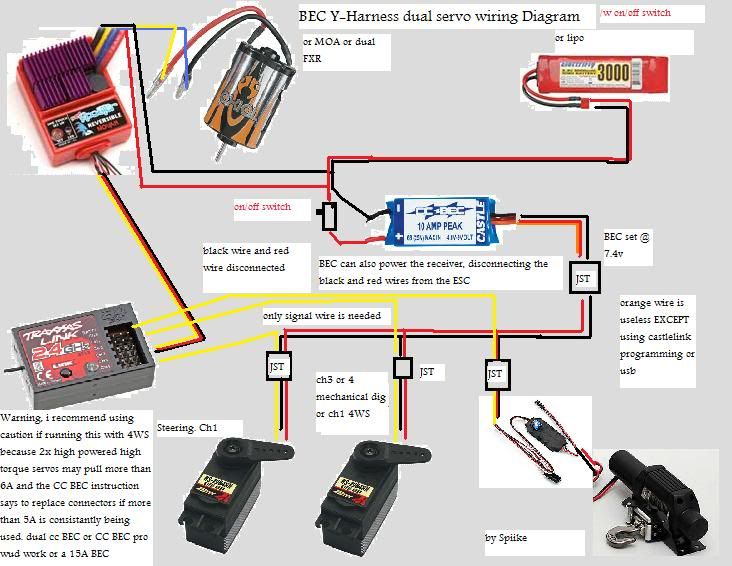
Last edited by Spiike; 09-26-2011 at 05:27 AM. Reason: made my own diagram
Spiike is offline   Reply With Quote
Old 09-26-2011, 06:56 AM   #149
I wanna be Dave
 
Join Date: Nov 2010
Location: 07456 N. NJ USofA
Posts: 8,314
Default

Quote:
Originally Posted by Spiike View Post
so some people say that connecting the black wire from the BEC to the receiver with the signal wire (when the BEC is only powering the servo) will stop glitches, but others say it runs 100% fine with only running the signal wire from the servo to the receiver. anyone have any input on this?

*edit* I dont think you need it at all and would not affect anything would it?

so does this seem right? and cover all or most?
There are too many variables to say do it one way or the other. It appears most Futaba radios (TX & RX) seem fine with the red & black from the BEC direct to the servo while other radios are more likely to need the black connected to the RX.
Try it one way yourself, switch if need be.

My son & I run Futaba's ( me = 3PM-x, he = 4PL) with the CC 10A BEC red & black direct to the servo with no radio glitching. YMMV
Charlie-III is offline   Reply With Quote
Old 10-03-2011, 02:03 AM   #150
Rock Crawler
 
Join Date: Jan 2011
Location: Okanagan
Posts: 540
Default

well so far so good, my receiver isn't lacking power like it did before, the 3A off my novak ESC runs the receiver and not very often do i full throttle at far distances with my ol' 27mhz ax1/ar1 combo, if i do turn to lipo and/or change the bec to higher voltage im ok, and not need to worry about the rx receiving higher voltage than it should. I did leave the black wire connected, and only removed the red wire to the receiver from the bec.
Spiike is offline   Reply With Quote
Old 10-19-2011, 03:32 PM   #151
Yashua
 
CREEPERBOB's Avatar
 
Join Date: Sep 2010
Location: Learn the parable of the fig tree
Posts: 3,661
Default

Okay guys and gals, i have a request.
I am getting ready to wire up my super bully, i have 2- tekin fxr's, 2- 7980 hitech servo's, 2- castle bec's and futaba r2104gf reciever all run off 3s lipo.
My question is does anyone have a diagram for this setup?
CREEPERBOB is offline   Reply With Quote
Old 10-19-2011, 04:01 PM   #152
Rock Crawler
 
Join Date: Jan 2011
Location: Okanagan
Posts: 540
Default

Quote:
Originally Posted by CREEPERBOB View Post
Okay guys and gals, i have a request.
I am getting ready to wire up my super bully, i have 2- tekin fxr's, 2- 7980 hitech servo's, 2- castle bec's and futaba r2104gf reciever all run off 3s lipo.
My question is does anyone have a diagram for this setup?
the diagram i made supports your setup, except only running 1 servo per castle BEC. add another ESC and splitting the deans 2 more times to accomidate the extra BEC and ESC. remove the winch (which was optional anyways) no dig? then a Y harness for both ESC to wire into the throttle would also finish the wiring off. but if you use dig, esc wires to the dig and the throttle and the dig switch wires would go to the receiver of course.
Spiike is offline   Reply With Quote
Old 10-24-2011, 09:37 AM   #153
Yashua
 
CREEPERBOB's Avatar
 
Join Date: Sep 2010
Location: Learn the parable of the fig tree
Posts: 3,661
Default

Quote:
Originally Posted by spiike View Post
the diagram i made supports your setup, except only running 1 servo per castle bec. Add another esc and splitting the deans 2 more times to accomidate the extra bec and esc. Remove the winch (which was optional anyways) no dig? Then a y harness for both esc to wire into the throttle would also finish the wiring off. But if you use dig, esc wires to the dig and the throttle and the dig switch wires would go to the receiver of course.

got it all figured out and running, easier than i thought.
CREEPERBOB is offline   Reply With Quote
Old 10-24-2011, 02:42 PM   #154
Rock Crawler
 
Join Date: Jan 2011
Location: Okanagan
Posts: 540
Default

Quote:
Originally Posted by CREEPERBOB View Post
got it all figured out and running, easier than i thought.
yeah its pretty easy once you understand it all. i also read that the CC BEC's wire only supports 5A. so if you have 2x 3A servo on 1 cc BEC, the positive wire needs to be upgraded, and little JST connectors don't support that much amps neither. so limiting the CCBEC to 1 servo and 1 small servo, and running the other high power/high torque servo on another CC BEC. or i heard that replacing the power wire to a higher gauge works too.
Spiike is offline   Reply With Quote
Old 10-24-2011, 02:47 PM   #155
Yashua
 
CREEPERBOB's Avatar
 
Join Date: Sep 2010
Location: Learn the parable of the fig tree
Posts: 3,661
Default

Quote:
Originally Posted by spiike View Post
yeah its pretty easy once you understand it all. I also read that the cc bec's wire only supports 5a. So if you have 2x 3a servo on 1 cc bec, the positive wire needs to be upgraded, and little jst connectors don't support that much amps neither. So limiting the ccbec to 1 servo and 1 small servo, and running the other high power/high torque servo on another cc bec. Or i heard that replacing the power wire to a higher gauge works too.

i've got seperate cc bec's on each 7980 set to 7.3 volts and they turn my 8" rover / moabs very easy.
CREEPERBOB is offline   Reply With Quote
Old 10-24-2011, 03:15 PM   #156
Rock Crawler
 
Join Date: Jan 2011
Location: Okanagan
Posts: 540
Default

Quote:
Originally Posted by CREEPERBOB View Post
i've got seperate cc bec's on each 7980 set to 7.3 volts and they turn my 8" rover / moabs very easy.
yeah thats what I would do too. i wouldnt risk runnin 2 of those on 1 bec unless you get that CC BEC PRO that does 20A i think it is. and i will probably recommend using the internal BEC on the ESC to run the receiver, as it will not be stepped down by voltage as much as if the receiver was wired to the bec. there is a slight voltage drain when using the servo that reduces the signal from to the receiver, thus limiting the range (not affected by 2.4ghz systems compared to 27mhz systems)

just doing a basic distance test in a field, i get an extra 20-30 feet when the ESC's BEC was wired to the receiver vs the BEC running servo and receiver.

other electronics may vary, this was tested with the Novak Super rooster with a 3A internal BEC. using an RC4WD 35T motor, a HS-645mg (ccbec set @ default), AX-1 AR-1 27mhz 2ch rx+tx, with winch and lights receiving own power from hijack deans.
Spiike is offline   Reply With Quote
Old 11-06-2011, 10:58 AM   #157
Yashua
 
CREEPERBOB's Avatar
 
Join Date: Sep 2010
Location: Learn the parable of the fig tree
Posts: 3,661
Default

I THOUGHT I'DE SHARE MY DIAGRAM FOR MY SUPER. EVERYONE DOES SOMETHING A LITTLE DIFFERANT AND THIS IS WHAT I CAME UP WITH AFTER MUCH RESEARCH AND COMPARISON'S.


CREEPERBOB is offline   Reply With Quote
Old 11-06-2011, 11:08 AM   #158
I wanna be Dave
 
Join Date: Nov 2010
Location: 07456 N. NJ USofA
Posts: 8,314
Default

Quote:
Originally Posted by CREEPERBOB View Post
I THOUGHT I'D SHARE MY DIAGRAM FOR MY SUPER. EVERYONE DOES SOMETHING A LITTLE DIFFERENT AND THIS IS WHAT I CAME UP WITH AFTER MUCH RESEARCH AND COMPARISON'S.
Ummm......the yellow signal wires go from the 2 servos to the RX, NOT from the 2 BEC's.

Last edited by Charlie-III; 11-06-2011 at 05:16 PM. Reason: Deleted drawing, it's been updated and no longer visible.
Charlie-III is offline   Reply With Quote
Old 11-06-2011, 04:19 PM   #159
Yashua
 
CREEPERBOB's Avatar
 
Join Date: Sep 2010
Location: Learn the parable of the fig tree
Posts: 3,661
Default

Quote:
Originally Posted by Charlie-III View Post
Ummm......the yellow signal wires go from the 2 servos to the RX, NOT from the 2 BEC's.

CORRECT,MY MISTAKE IN DRAWING IT ,ALSO WITH THE GROUND WIRE TOO. HERE IS A EDITED DRAWING.
Attached Images
 

Last edited by CREEPERBOB; 11-06-2011 at 04:23 PM.
CREEPERBOB is offline   Reply With Quote
Old 11-06-2011, 05:14 PM   #160
I wanna be Dave
 
Join Date: Nov 2010
Location: 07456 N. NJ USofA
Posts: 8,314
Default

Quote:
Originally Posted by CREEPERBOB View Post
CORRECT, MY MISTAKE IN DRAWING IT, ALSO WITH THE GROUND WIRE TOO. HERE IS AN EDITED DRAWING.
The ground going to the RX is an option. Not normally needed with Futaba radios, may be needed with other radios.

Now, should I be really picky and say that the "ground" (black or brown wire) is normally towards the outside edge of the RX??


Last edited by Charlie-III; 11-06-2011 at 05:42 PM. Reason: change "red" to "brown"....duhhhhh
Charlie-III is offline   Reply With Quote
Reply


Posting Rules
You may not post new threads
You may not post replies
You may not post attachments
You may not edit your posts

BB code is On
Smilies are On
[IMG] code is On
HTML code is On
Trackbacks are On
Pingbacks are On
Refbacks are On


All times are GMT -6. The time now is 11:53 AM.


Powered by vBulletin® Version 3.8.7
Copyright ©2000 - 2024, vBulletin Solutions, Inc.
Content Relevant URLs by vBSEO ©2011, Crawlability, Inc.
Copyright 2004-2014 RCCrawler.com