| |
| |||||||
 |
| | LinkBack | Thread Tools | Display Modes |
 02-24-2009, 01:16 PM
| #1 |
| Powered by Awesome   Join Date: Sep 2004 Location: Parker, Colorado
Posts: 3,622
|
Figured this was a good info for those of us who are broke or has one of these laying around. Warning: This can be dangerous to preform... if you decide to preform this operation, any and all information held within is mearly for informative access and anything you choose to do is upon yourself and you will be held responsable for any injury that may occur to yourself or others for you not knowing what you are doing. With that being said.... Line voltage can kill (anything above 30 milliamps/volts can kill you in a matter of time if it somehow penetrates your skin), and at the very least give you a painful shock. Make sure that you have removed the power cord before doing the conversion and have discharged the capacitors as described in the steps below. This information was supplied at: http://www.wikihow.com/Convert-a-Com...b-Power-Supply How to Convert a Computer ATX Power Supply to a Lab Power Supply Computer power supplies cost around US$30,but RC Power supplies can run you $100 or more! By converting the cheap (free) ATX power supplies that can be found in any discarded computer, you can get a phenomenal lab power supply with huge current outputs, short circuit protection, and very tight voltage regulation.  STEPS 1. Unplug the power cord from the back of the computer. "Harvest" a power supply from a computer by opening up the case of the computer, locating the gray box that is the power supply unit, tracing the wires from the power supply to the boards and devices and disconnecting all the cables by unplugging them. 2. Remove the screws (typically 4) that attach the power supply to the computer case and remove the power supply. 3. Cut off the connectors (leave a few inches of wire on the connectors so that you can use them later on for other projects). 4. Discharge the power supply by either letting it sit unconnected for a few days, or by attaching a 10 ohm resistor between a black and red wire (from the power cables on the output side). Using a resistor will only take a few seconds to fully discharge the power supply. 5. Gather the parts you need: binding posts (terminals), a LED with a current-limiting resistor, a switch (optional), a power resistor (10 ohm, 10W or greater wattage, see Tips), and heat shrink tubing.  6. Open up the power supply unit by removing the screws connecting the top and the bottom of the PSU case. 7. Bundle wires of the same colors together. If you have wires not listed here (brown, etc), see the Tips.  The color code for the wires is: Red = +5V, Black = Ground (0V), White = -5V, Yellow = +12V, Blue = -12V, Orange = +3.3V, Purple = +5V Standby (not used), Gray = power is on (output), and Green = Turn DC on (input). 8. Drill holes in a free area of the power supply case by marking the center of the holes with a nail and a tap from the hammer. Use a Dremel to drill the starting holes followed by a hand reamer to enlarge the holes until they are the right size by test fitting the binding posts. Also, drill holes for the power ON LED and a Power switch (optional).  9. Screw the binding posts into their corresponding holes and attach the nut on the back.  10. Connect all the pieces together. Connect one of the red wires to the power resistor, all the remaining red wires to the red binding posts; Connect one of the black wires to the other end of the power resistor, one black wire to a resistor (330 ohm) attached anode of the LED, one black wire to the DC-On switch, all the remaining black wires to the black binding post; Connect the white to the -5V binding post, yellow to the +12V binding post, the blue to the -12V binding post, the gray to the cathode of the LED; Note that some power supplies may have either a gray or brown wire to represent "power good"/"power ok". (Most pSU's have a smaller orange wire that is used for sensing-- 3.3V- and this wire is usually paired at the connector to another orange wire. Make sure this wire is connected to the other orange wires, otherwise your lab power supply won't stay on.) This wire should be connected to either an orange wire (+3.3V) or a red wire (+5V) for the power supply to function. When in doubt, try the lower voltage first (+3.3V). If a power supply is non ATX or AT compliant, it may have its own color scheme. If yours looks different that the pictures shown here, make sure you reference the position of the wires attached to the AT/ATX connector rather than the colors.  11. Connect the green wire to the other terminal on the switch. Make sure that the soldered ends are insulated in heatshrink tubing. Organize the wires with a electrical tape or zip-ties. 12.  13. Check for loose connections by gently tugging on them. Inspect for bare wire, and cover it to prevent a short circuit. Put a drop of super-glue to stick the LED to its hole. Put the cover back on. 14. Plug the power cord into the back and into an AC socket. Flip the main switch on the PSU. Check to see if the LED light comes on. If it has not, then power up by flipping the switch you placed on the front. Plug in a 12V bulb into the different sockets to see if the PSU works, also check with a digital voltmeter. It should look good and work like a charm!  Last edited by TwistedXT; 02-24-2009 at 01:28 PM. |

|  |
| Sponsored Links | |
| | |
|
02-24-2009, 01:17 PM
| #2 |
| Powered by Awesome Join Date: Sep 2004 Location: Parker, Colorado
Posts: 3,622
| Tips: Options: You don't need an additional switch, just connect the green and a black wire together. The PSU will be controlled by the rear switch, if there is one. You also don't need an LED, just ignore the gray wire. Cut it short and insulate it from the rest. Some newer power supplies will have "voltage sense" wires that need to be connected to the actual voltage wires for proper operation. In the main power bundle (the one with 20 wires), you should have four red wires and three orange wires. If you only have two orange wires, you should also have a brown wire which must be connected with the orange. If you only have three red wires, another wire (sometimes pink) must be connected to them. If the power supply does not work, that is, no LED light, check to see if the fan has come on. If the fan in the power supply is on, then the LED may have been wired wrong (the positive and negative leads of the LED may have been switched). Open the power supply case and flip the purple or gray wires on the LED around (make sure that you do not bypass the LED resistor). If you are not sure of the power supply, test it in the computer before you harvest. Does the computer power on? Does the PSU fan come on? You can place your voltmeter leads into an extra plug (for disk drives). It should read close to 5V (between red and black wires). A supply that you have pulled may look dead because it does not have a load on its outputs and the enable output may not be grounded (green wire). ATX power supplies are switched-mode power supplies (info at http://en.wikipedia.org/wiki/Switche...power_supply); they must always have some load to operate properly. The power resistor is there to "waste" energy, which will give off heat; therefore it should be mounted on the metal wall for proper cooling (you can also pick up a heatsink to mount on your resistor, just make sure the heatsink doesn't short anything out). If you will always have something connected to the supply when it is on, you may leave out the power resistor. You can also consider using a lighted 12v switch, which will act as the load necessary to turn on the power supply. Feel free to add some pizazz to the dull gray box. You can also convert this to a variable power supply - but that is another article (hint: Uses a 317 IC with power transistor). The voltages that can be output by this unit are 24v (+12, -12), 17v (+5, -12), 12v (+12, 0), 10v (+5, -5), 7v (+12, +5), 5v (+5, 0) which should be sufficient for most electrical testing. Many ATX power supplies with a 24-pin connector for motherboards will not supply the -5V lead. Look for ATX power supplies with a 20-pin connector, a 20+4-pin connector, or an AT power supply if you need -5V. If you DO have a sense wire for the 3.3v. , connecting the the 3.3 v. part of the supply, using the 3.3v. voltage as a buck voltage against, say the 12v. to get 8.7v. will not work. You will see 8.7 v. with a volt meter but when you load that 8.7v. circuit the power supply may go into protective mode and shut the whole supply down. You can add a 3.3 volt output (such as to power 3V battery-powered devices) to the supply by hooking the orange wires to a post (making sure the brown wire remains connected to an orange wire) but beware that they share the same power output as the 5 volt, and thus you must not exceed the total power output of these two outputs. To get more room you can mount the fan on the outside of the PSU case If you don't feel like soldering nine wires together to a binding post (as is the case with the ground wires) you can snip them at the PCB. 1-3 wires should be fine. This includes cutting any wires that you don't ever plan on using. The +5VSB line is +5V standby (so the motherboard's power buttons, Wake on LAN, etc. work). This typically provides 500-1000 mA of current, even when the main DC outputs are "off". It might be useful to drive an LED from this as an indication that the mains are on. The -5v rail was removed from the ATX specification and does not exist on all ATX power supplies. The fan on a PS can be quite loud, its designed to cool a relatively heavily loaded PS as well as the computer. The is the possibility of just clipping the fan but is not a good idea. A work around is to cut the red wire going to the fan (12V) and connect it to a red wire going out of the PS (5V). Your fan will now be spinning significantly slower and thus quieter, but still provide some cooling. If you plan to draw a lot of current from the PS this might be a bad idea, be your own judge and see how hot the thing gets. Warnings: Line voltage can kill (anything above 30 milliamps/volts can kill you in a matter of time if it somehow penetrates your skin), and at the very least give you a painful shock. Make sure that you have removed the power cord before doing the conversion and have discharged the capacitors as described in the steps above. Do not touch any lines leading to capacitors. Capacitors are cylinders, wrapped in a thin plastic sheath, with exposed metal at the top with a + or K usually. Solid-state capacitors are shorter, a little wider in diameter, and do not have a plastic sheath. They retain a charge much like batteries do, but unlike batteries, they can discharge extremely fast. Even if you have discharged the unit, you should avoid touching any points on the board except where necessary. Use a probe to connect anything you might touch to ground before beginning any work. When drilling the metal case, make sure no metal filings get inside the PSU. These could cause shorts, which in turn could cause a fire, extreme heat or dangerous electrical spikes on one of your outputs which will break your new lab power supply which you worked so hard on. A computer power supply is fine for testing purposes, or for running simple electronics (eg battery chargers, soldering irons) but will never produce power like a good lab power supply, so if you intend on using your power supply for more than just testing, buy yourself a good lab supply. There is a reason they cost so much. It is strongly recommended that you discharge the capacitors. Plug in the power supply, turn on the power (short the Power (green) wire to ground, then unplug the power supply until the fan stops spinning. This will almost certainly void any warranty. Things You'll Need An obsolete computer with an ATX power supply of any rating above 150 Watt. Wire cutters, needle nose pliers, drill, reamer, soldering wire, soldering iron, any kind of tape that sticks, heat shrink tubing(found at some electronics stores[IE: frys, radioshack, and ebay]) Binding posts for output terminals, LED, current limiting resistor for the LED(330 ohms[also can be found on the net or some electronics stores(I'm not sure if they have it...)]), power resistor to load the power supply, a low wattage switch. Sources and Citationshttp: //web2.murraystate.edu/andy.batts/ps/powersupply.htm |
|
| |
|
02-28-2009, 09:21 PM
| #3 |
| Rock Crawler Join Date: Sep 2008 Location: N.E. Mpls
Posts: 854
|
I currently have a pc converted p/s puttoing out 12.7 volts with 19 amps. I run 3 chargers off it and works great. Ok now for the juicy stuff, there is some mod done with resistors that will bring the voltage up to par for chargers. I have 2 pc p/s that I have tried to convert and just couldnt get the voltage hi enough to power chargers... Any hints??? Something about adding resistors to make it work harder(load) I tried many combinations of resistors to make this work. Heck Ive got about 70$ total into trying to get this to work. The project is now in a box in the basement.... Any help to finish this project would be awsome !!!! Ill try and dig up my old files. Tho I did loose all the links to the info I had grrr Thanks in advance Dave |
|
| |
|
03-01-2009, 03:46 PM
| #4 |
| Pebble Pounder Join Date: Dec 2008 Location: Tomball, Tx
Posts: 168
|
Yes, you can tweak the power supply to put out more voltage, but it is kind of like overclocking a cpu, you takes your chances. using a 10 ohm 10 watt 'sandbar' resistor that can be found at radio shack (part #271-0132) will give you sufficient voltage to run a charger.
|
|
| |
|
03-02-2009, 05:19 AM
| #5 |
| Rock Crawler Join Date: Sep 2008 Location: N.E. Mpls
Posts: 854
|
From my exp, some p/s or undervolted (11.5) and soon as you apply a load ythe voltage drops and off goes the charger.... Ive got 2 p/s with that issue... Any info on where (specifically) that this resistor goes??? Thanks Dave |
|
| |
|
03-02-2009, 06:18 PM
| #6 |
| Pebble Pounder Join Date: Dec 2008 Location: Tomball, Tx
Posts: 168
|
the resistor will go between red(5v) and black(gnd) it does need to be mounted to a heatsink of some type. I was lucky enough to have this one right by the fan. and i reversed the airflow too.  i removed a bunch of the wires that i didn't use. the grey, purple, blue and brown got heat shrink over each end, and a big piece over that to keep them from shorting. i kept one orange(3.3v) and black for future use, but i don't think i will ever need them.  here is where i connected to the binding posts. yeah, the three leads each to the 12v (yellow) side are overkill, but this was the first one i built. i will sometimes use the 5v(red) for bench testing receiver and servos. that way, i don't have to drag out a battery to do it.  hope this helps some |
|
| |
|
04-03-2009, 09:20 PM
| #7 |
| Newbie Join Date: Mar 2009 Location: Boiling Springs
Posts: 18
|
Our local landfill has a place set aside for old computers and such. It's free to take. Great place to pick up a power supply (PSU) or two. Also, larger businesses are always replacing old (but perfectly good) computers. Also very "green", after all you are "recycling". Power supplies can be had for free if you know where to look and how to ask.  |
|
| |
|
08-29-2009, 01:05 PM
| #8 | |
| Quarry Creeper Join Date: Aug 2009 Location: Philadelphia, PA
Posts: 352
| Quote:
The resistor must have good air flow becuase it WILL get hot. I mounted mine on the bottom of the chassis that I lightly sanded, and put heat sink grease to dissipate the heat. Then I pop riveted into the case near the exhuast vent. I also added a usb jack for charging mp3 players and cell phones http://web2.murraystate.edu/andy.bat...owersupply.htm | |
|
| |
|
12-03-2009, 10:57 AM
| #9 |
| I wanna be Dave  Join Date: Feb 2006 Location: Campbell, CA 4 hrs 2Rubicon !
Posts: 2,044
|
I could build one of these, but surely there is an easier and better suitable power supply out there. I have seen the Peak power supply http://www.rctoys.com/rc-toys-and-pa...ERS-POWER.html Is there a poplar well know box people like ? |
|
| |
|
12-07-2009, 09:21 PM
| #10 |
| Quarry Creeper Join Date: Aug 2009 Location: Philadelphia, PA
Posts: 352
|
With shipping that is well over $100 to the states. I just got a 400 watt ps for free at the computer shop it puts out 17 amps and 10 amps on the second rail @ 12 volts . Not to mention the 3 and 5 volt rails. It just needs a fan. A resistor and some terminals about $10-15 max. The one I built already also uses the negative voltages too! So I have 6 terminals +12, -12, +5, -5, +3 and gnd. You can mix voltages to get different output voltages e.g. positive +12 and a negative +5 = about 7 volts. Great for testing esc's. The combinations are 15 positive and 15 negative voltages that can be created. It is more useful than a fixed voltage ps (power supply). I just wish I had an amp meter to see the output of the combinations! Any questions? 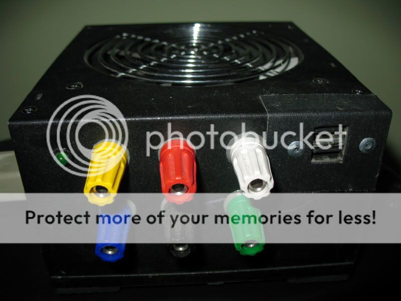 Last edited by racerfred; 03-12-2010 at 06:51 PM. Reason: moved picture |
|
| |
|
12-15-2009, 02:40 PM
| #11 |
| Rock Stacker Join Date: Nov 2009 Location: New Ipswich
Posts: 73
|
Wont something like this do the same thing? http://hobbyking.com/hobbycity/store...A_Power_Supply |
|
| |
|
12-16-2009, 09:21 PM
| #12 | |
| Quarry Creeper Join Date: Aug 2009 Location: Philadelphia, PA
Posts: 352
| Quote:
Why do people make their own parts, becuase they like to make things different/better or take pride in doing something themselves. To each his own! | |
|
| |
|
12-18-2009, 10:32 PM
| #13 | |
| Rock Crawler Join Date: Jan 2007 Location: West Seneca
Posts: 770
| Quote:
| |
|
| |
|
12-20-2009, 12:36 PM
| #14 |
| Quarry Creeper Join Date: Aug 2009 Location: Philadelphia, PA
Posts: 352
|
The red +5v to one end of the resistor and the other end is black (ground). There are several red, yellow, orange and black wires that are next to each other. So it doesn't matter which red or black you use becuase they are the same. On better power supplies there are two or more separate 12 v rails or outputs.
|
|
| |
|
12-20-2009, 11:26 PM
| #15 |
| Quarry Creeper Join Date: Aug 2009 Location: Philadelphia, PA
Posts: 352
|
A pic of the resistor, my value of resistor is based on THIS ps (power supply)  A pic of all the wiring  I made a few changes to the wiring purple and black to the usb port gray and black to the "on led" changed the +12, +5, 3, and gnd to 14 awg changed the power jack to a filtered jack The specs for the ps are the MAX output, most ps are 70% efficent. So an 21 amp ps would be rated at 14 amps give or take. Last edited by racerfred; 03-12-2010 at 06:53 PM. Reason: moved picture |
|
| |
|
12-24-2009, 09:08 PM
| #16 | |
| Rock Crawler Join Date: Jan 2007 Location: West Seneca
Posts: 770
| Quote:
Thanks charger isnt giving me voltage error when i turn it up any more. | |
|
| |
|
12-25-2009, 07:51 AM
| #17 |
| Quarry Creeper Join Date: Aug 2009 Location: Philadelphia, PA
Posts: 352
|
The voltage was dropping because you were drawing more amps from the power supply. That is why you have to play with the resistor value, so when you apply a load it will not drop below the min needed for the charger. Without a load mine sits at 12.15vdc.
|
|
| |
|
01-10-2010, 01:23 PM
| #18 |
| Newbie Join Date: Dec 2009 Location: Roeland Park
Posts: 14
|
Did I miss where to size the power resistor? Given that voltures = rabbits x indians and power is voltures / rabbits ^2 or indians ^2 times rabbits or voltures times indians - what is the constant, since you can pick the voltage via the taps? P = V * I P = V / R^2 P = R * I^2 If you need 12 volts for a charger - can you use the 18 volt tap (ensure always getting the enough voltage) or will this over drive the charger? If you go with the 18 volts and need 12 amps - a 300 watt power supply will suffice? Having a 300 watt power supply at 18 volts and need 12 amps - what would the correct resistor be and does this have an affect since the power supply will be looking at the load that is plugged in? I've seen a lot of it depends on the power supply for which resistor to select - but what does it depend on? Thanks -Notpalc |
|
| |
|
01-10-2010, 10:11 PM
| #19 |
| Quarry Creeper Join Date: Aug 2009 Location: Philadelphia, PA
Posts: 352
|
Don't use 18 volts most chargers take up to 13-14ish volts. Using a higher voltage will destroy most chargers. The power supplies today need a load on the output to regulate it, that is why we use resistors. There are a number of variables to consider 1. the chargers amperage needs, 2. different power supplies. My 350 watt power wiil do 12 amps, but the manufacture rates it at 18 amps. I factor in the 70%efficiency and then some, i do 66% (easy math). The voltage will drop some when a load is applied (charger), the charger give voltage errors at 10 or 11 volts depending on the charger. That is why we want to get the voltage in the 12 v range. The only real way to figure out what resistor to use is to measure the voltage with a meter. If the voltage is too low, lower the value of the resistor. Don't over do it with trying to get a high +12, because it may over work the power supply. Bottom line, there is no telling which resistor to use because of the different manufactures designs. It's trial and error. |
|
| |
|
01-11-2010, 08:34 AM
| #20 | |||
| Newbie Join Date: Dec 2009 Location: Roeland Park
Posts: 14
| Quote:
Quote:
Quote:
Now I just have to get my parts and a charger Thanks for the clarifications. -Notpalc | |||
|
| |
|
 LinkBacks (?)
LinkBack to this Thread: http://www.rccrawler.com/forum/electronics/163458-modding-pc-power-supply-into-12-volt-supply-your-dc-charger.html | ||||
| Posted By | For | Type | Date | |
| Using a Computer Power Supply To Run a Charger - R/C Tech Forums | This thread | Refback | 10-05-2011 05:49 PM | |
| |


 Linear Mode


