| |
| |||||||
 |
| | LinkBack | Thread Tools | Display Modes |
 06-20-2009, 12:50 PM
| #21 |
| Rock Crawler Join Date: Feb 2008 Location: UK
Posts: 818
|
Wow - never seen that Tx before! Looks big enough to fit all the DX components, but you'll be on your own with the conversion. If you get the Mars EX-1 (same as mine) we can learn from each other's mistakes. EX-1 will cost more, though. If you can get that old Tx for $15 (no extras for shipping), I'd say go for it. If it all goes horribly wrong, you've not lost much. The DX6i only has space for 4 AA batteries. I'm using 2100mAH rechargeables. They seem to last for a long time, so no need for a bigger pack. |

|  |
| Sponsored Links | |
| | |
|
06-20-2009, 01:02 PM
| #22 |
| I wanna be Dave  Join Date: Feb 2006 Location: Campbell, CA 4 hrs 2Rubicon !
Posts: 2,044
|
yea, it's $14. in shipping bid start at $1. cant beat that . but still lots to decide on. would be cool to share our project and stuff thanks |
|
| |
|
06-21-2009, 01:32 AM
| #23 |
| Rock Crawler Join Date: Feb 2008 Location: UK
Posts: 818
|
Just realised that the Mars already has the switches needed for programming the DX6i, so I don't need the scroll wheel. Just below the steering wheel is a black thumbwheel. This is actually a 2-way rotary encoder, same as the scroll wheel. The silver button between the steering wheel and the thumbwheel is a momentary pushbutton, same as pushing the scroll wheel. Using these instead of transplanting the scroll wheel leaves me space for more controls (where the original display was). I'll add a rotary pot and dual rate switch for the rudder channel, allowing independent rear steer. I'll also put the elevator channel 3-way and rate switch here. The right side now just needs the 3-way steering mix switch and diff lock switches. I'm off to the buggy track in an hour to test the modified Mars/DX6i combo. |
|
| |
|
06-21-2009, 12:41 PM
| #24 |
| Rock Crawler Join Date: Feb 2008 Location: UK
Posts: 818
|
Went to the buggy track with the 2 Txs joined by cables - throttle and steering worked perfectly. Was all set to go ahead when I found a problem using the Tx with my Venom - as soon as I flick one of the steering mixes, the rear servo goes off neutral! There's another post on here - "need help to program DX6i for 4ws", posted by "sly". He's got the same problem. |
|
| |
|
06-21-2009, 02:16 PM
| #25 |
| Rock Crawler Join Date: Feb 2008 Location: UK
Posts: 818
|
I think I might have solved the rear servo problem when using a mix. I added a 1K resistor to the positive side of the steering pot. The aileron channel is now almost centred when I look at the "monitor" display screen. When I use a mix, the rear servo just moves slightly with the steering at neutral. I'll have to get a miniature 1K pot and wire that in series with the main steering pot. By tweaking the mini pot, I should be able to balance the aileron channel perfectly, so the rear servo won't change it's neutral position when I engage a mix. I think the problem is that the KO Mars pot isn't exactly centred in it's resistance range when the wheel is centred. It doesn't matter for normal steering, because you can adjust the subtrim and travel to get everything working. Problem is, a mix uses the physical stick position of the master channel to control the slave channel, not the trimmed position. After my successful track testing earlier today, I'm more determined than ever to get this working! |
|
| |
|
06-22-2009, 10:07 PM
| #26 |
| I wanna be Dave Join Date: Feb 2006 Location: Campbell, CA 4 hrs 2Rubicon !
Posts: 2,044
|
Damm your good . . . sounds like it will be a fine tuned machine I'm still thinking what direction to go with mine |
|
| |
|
06-23-2009, 12:51 AM
| #27 | |
| Rock Crawler Join Date: Feb 2008 Location: UK
Posts: 818
| Quote:
I've ordered some multi-turn trimpots to balance the two steering channels. Hopefully I can totally eliminate any imbalance between the front and rear servos when switching mixes. I've decided to add a pot with a rotary knob to allow independent rear-only steering. By flicking the rudder D/R switch I can disable the pot. I'm also thinking about making the steering wheel able to control both steering channels independently, using a 6PDT rotary switch. This would connect the steering pot to either channel. The other channel would be connected to a passive resistor network to keep it centred. In the "normal" position, the wheel will directly control the front servo, with the rear servo controllable using the mixes. In the "rear" position, the wheel would control the rear servo, with the front servo locked straight ahead. Seems like this should work, but I'm not sure what will happen as both channels go "open" as the switch contacts change over. It's a shame I can't just use dual rates to achieve this, but turning the front channel rate down also affects the rear channel in a mix. I should have all the parts I need by the end of the week. I'll prove that all my switching options work properly, then start the build proper at the weekend. | |
|
| |
|
06-23-2009, 08:13 AM
| #28 |
| I wanna be Dave Join Date: Feb 2006 Location: Campbell, CA 4 hrs 2Rubicon !
Posts: 2,044
|
Sounds sweet, I think it's cool that you can make options on steering, but I would think it would become cumbersome to have to switch switches and or push buttons just to control front and then rear steering. it seems your hand is going to be busy moving to different switches, but that's just me. When I do rear steer for my D6 pistol I want my rear steer ready and easy to control while doing front simultaneously IS there a Dual POT so you can control steering with one hand ? one wheel behind the other, like have dual wheels on top of each other, Use the the Front main steering wheel for always turning the front but when you want an extreme right turn (turn the rear) you press a button or Momentary switch to activate the rear then press a 2nd button and then it can Crab walk, all using the same wheel. or when you want both front and rear independent of each other use the dual POT dual wheel what do you think ? Can you help me understand this part " with the rear servo controllable using the mixes. " how are using using mixes, Is it how I described above ? Last edited by toy4crawlin; 06-23-2009 at 08:32 AM. |
|
| |
|
06-23-2009, 11:00 AM
| #29 |
| Rock Crawler Join Date: Feb 2008 Location: UK
Posts: 818
|
It's like you say, the mixes allow the option of front steering only, front and rear working opposite directions (full 4ws) and front and rear working same direction (crab steer). All the programmable mixes do is use one input control (in this case the steering wheel for the front steering) to automatically control a second channel (in this case rudder channel for rear steering). You can trigger the mixes on a DX6i using any of the following switches: Ail D/R, Elev D/R, Mix, Flap. You can use any switching method that suits you - 2 position toggle or momentary pushbutton. I want to combine the 2 mixes on one switch, so I'm using a 3 position toggle. If you prefer a thumb-operated pushbutton, that's easy to do. If you wanted totally independent front and rear steering, with or without the mixes, you could do as you suggest - use 2 concentric steering wheels and pots. I've seen concentric pots before, normally used on audio equipment where the volume knob is surrounded by a balance ring, or where bass and treble controls are stacked. No idea if these are still available, or if they would be suitable. Audio pots are normally logarithmic, you need linear for a Tx. You'd still need to make your own wheel hardware. I've done next to no crawling yet, but I'd envisage using front steering only 95% of the time, 4ws or crab 5% of the time. Rear-only might occasionally be useful where you want to steer as you climb, but would get more grip if the front wheels were straight ahead. The control possibilities are limited only by our imaginations! My way seems logical to me, but it's pretty easy to change the switches as needed. |
|
| |
|
06-23-2009, 06:14 PM
| #30 |
| I wanna be Dave Join Date: Feb 2006 Location: Campbell, CA 4 hrs 2Rubicon !
Posts: 2,044
|
Awesome ! sounds like you really are on the know of these components that would work great. I would love to have the push button mixes on a pistol. Now that I think about it more I don't like the stacked pots . But maybe a small rear pot for my little finger towards the bottom for small movement rr str. How would you suggest measuring my pots ? they are not marked . I think it's best for me to off the DX6 and get the 6i. it's so funny and ironic that if you did get the pistol idea from me that you are doing before I am. thanks |
|
| |
|
06-23-2009, 06:59 PM
| #31 |
| RCC Addict Join Date: Jun 2009 Location: QLD, Australia
Posts: 1,512
|
I had an idea for a custom pistol radio but its a bit out there  Thanks in advance Kieren |
|
| |
|
06-24-2009, 12:47 AM
| #32 | |
| Rock Crawler Join Date: Feb 2008 Location: UK
Posts: 818
| Quote:
If the pots aren't marked, the only way is to measure them with a multimeter between the 2 outside contacts. You have to disconnect them from the circuit board to get a good measurement. Some pots are marked like "4K5". This is 4.5Kohms. They put the multiplier (K or M) in place of the decimal point. How would you operate the pot with your pinky? | |
|
| |
|
06-24-2009, 01:04 AM
| #33 | |
| Rock Crawler Join Date: Feb 2008 Location: UK
Posts: 818
| Quote:
I know what you mean about trigger throttles not having great control. For me, it is lack of travel that makes triggers a bit imprecise. The travel on my modified KO Tx is almost double the original. Making a case totally from scratch would be tricky. That's why I planning on adapting my KO Mars. The basic structure will be altered as necessary with a couple of fascia panels and an extended rear head. If you want to start from scratch, the only practical way I can think of is to carve a "plug" from balsa, then take a mould from the plug. You could then cast the case using 2-part resin, or lay it up in glassfibre. Resin cast would be simplest, as you could use low-temperature latex to create the mould. Suspend the carved plug in a box, fill the box with latex. once cooled, cut the mould from the plug, leaving 2 half-moulds. Slush-cast with the 2-part resin. This method would allow under-cuts, as the mould material is flexible. Glassfibre needs a rigid mould using plaster or similar, so no undercuts. Another alternative would be to vacuum-form over the plug, then lay some glassfibre on the inside of the thin vacuum moulded shell. | |
|
| |
|
06-24-2009, 09:46 AM
| #34 |
| Rock Crawler Join Date: Feb 2008 Location: UK
Posts: 818
|
Fitted a 2K multi-turn trim pot in series with the wheel pot - steering now balances perfectly. No movement of the rear servo when I engage one of the mixes. Everything seems to work OK, so it's time to rip the DX6i apart and start measuring up for the case mods. |
|
| |
|
06-24-2009, 12:02 PM
| #35 |
| Rock Crawler Join Date: Feb 2008 Location: UK
Posts: 818
|
DX6i is now stripped down - here's the parts I don't need for the conversion: 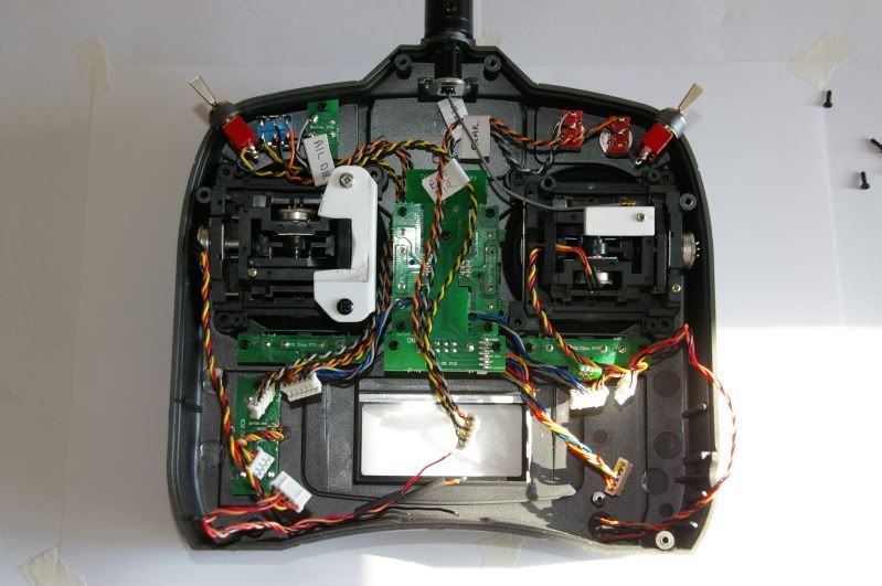 And here are the parts that I do need - not much to it: 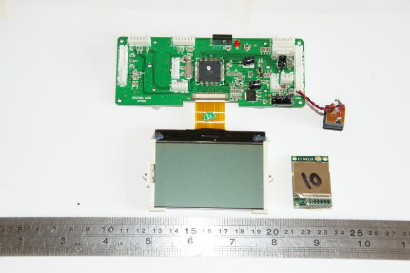 The only other parts from the DX6i that are needed are the antenna, the beeper and the wiring harnesses. The main PCB and display fit quite nicely inside the KO case:  There is one main fixing screw that's obscured by the PCB, so I'll have to make a new fixing a few mm over to the outer edge. There's not enough depth inside the case - the trigger mechanism will foul the PCB, so I'll have to build a new rear housing to make the case half an inch deeper. A few pieces of black 2mm styrene sheet, plus some clear perspex for the display panel cover, will do the job. It's a shame that the Tx module (small PCB sticking out the top) is in the wrong place to fit neatly. I'm not sure whether to extend the top of the case, to hold this module and the antenna, or to relocate the module by replacing the pins with some wires. This is probably the most critical part of the conversion, so I'm inclined to build the case around it. Rear case: 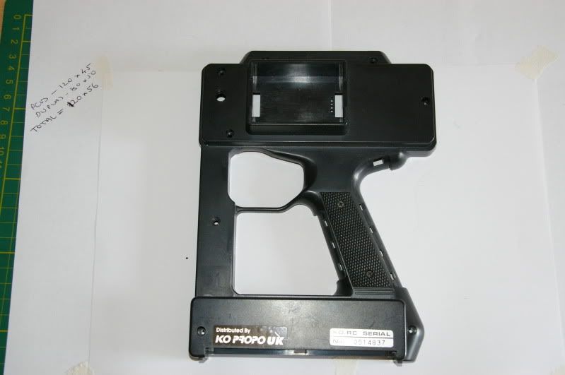 Time to sit back and think about this before I start cutting wires. Hope to make a start on the actual build on Saturday. |
|
| |
|
06-24-2009, 12:30 PM
| #36 |
| I wanna be Dave Join Date: Feb 2006 Location: Campbell, CA 4 hrs 2Rubicon !
Posts: 2,044
|
Holy cow, I cant believe how much you are able to leave behind Like to see your new parts though As for the Module sticking out, you could solder on some wires and relocate it, if for some reason you got glitches you could just put it back . How tall is that board ? 4 3/4 x 2" ? how deep is the case? surprised it's not deep enough. Man, you are getting way ahead of me, wish I had the 6i instead , so jealous, seeing one of my idea's come to life by someone else LOL |
|
| |
|
06-24-2009, 12:55 PM
| #37 |
| Rock Crawler Join Date: Feb 2008 Location: UK
Posts: 818
|
Measurements are close enough - I've just noticed that I actually wrote them down on the paper in the rear case pic. They're in millimetres, as we're almost fully metric over here. I tend to use metric for small measurements and feet & inches for bigger ones. I'm still waiting for a couple of parts to arrive by mail. I'll add a pic of all the parts as soon as they arrive. Thinking about the module, it looks like the connector used to join it to the main PCB is the same as a PC header - I may be able to make an extension lead for it, rather than soldering cables directly to the PCBs. The aim is to make this fully-reversible, so that I can put the DX6i back to standard if needed. The case itself is deep enough, but the trigger mechanism sits slap-bang in the middle of where the PCB need to go. The whole PCB/display/wiring harness needs about 18mm (3/4") clearance inside the case. With the trigger in the way, I've got about 12mm. I've also got to think about how I'll actually get the case closed up when all the wiring is completed - Everything will be in the front half, except for the main PCB, so there'll be a lot of wires to cram inside. A bit of extra space might be useful. |
|
| |
|
06-24-2009, 04:52 PM
| #38 |
| RCC Addict Join Date: Jun 2009 Location: QLD, Australia
Posts: 1,512
|
Hi Clockworks The pin pattern on the 2.4ghz module looks awful similar to internal usb connections in a computer. If you are looking for a cable to extend it that might be the go Just check your local computer shop.With the stubby stick I was thinking of having that on the back of the handle so you can control it with your thumb. Just like on a stick radio. Yeah thanks for the ideas for what I could make it out of . I notice your no taking the pots for the elevator and rudder. I read you are going to connect a 6 pos rotary switch for rear steer, but what are you going to do with the other channel? Are you going to connect a 3 pos switch? If so is there a special type so you don't have to connect it to the pot to get centre position? I thought you could use resitors on the centre wire maybe? Cheers Kieren |
|
| |
|
06-25-2009, 12:40 AM
| #39 |
| Rock Crawler Join Date: Feb 2008 Location: UK
Posts: 818
|
I thought the pins looked like a PC header, too. Unfortunately, the RF module uses a 2mm pitch connector. PCs use 1/10" (2.54mm) pitch. I need to extend the top of the case to hold the antenna, which is too big to fit in the original telescopic antenna mount. I might as well make this extension fit the RF module as well. I'll also gain some space for more switches and knobs - the 2 existing switch panels are going to be very cluttered. Stubby stick on the back of the handle sounds like a good idea for drivers who's thumbs are more responsive than their forefingers. You'd probably need a greater deflection angle (than with a stock stick) to compensate for the shorter stick. I'm planning on fitting a pot for the rudder (rear steer) channel, as well as switches to control the mixes. The spare channel (elevator) will have 2 methods of control, for future flexibility: A small pot with a knob for fully-proportional operation A 3-way switch with a couple of resistors to fix the centre position, like you say. I'll also fit a changeover switch (DPDT) to switch between the 2 control methods, plus a D/R switch. If I get home from work at a reasonable time tonight, I'll start cutting the case. |
|
| |
|
06-26-2009, 01:35 PM
| #40 |
| Rock Crawler Join Date: Feb 2008 Location: UK
Posts: 818
|
I've been busy with the Dremel. I've cut a big hole in the rear case and started work on the extension for the rear housing: 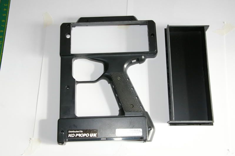 Unfinished rear housing fitted to case. 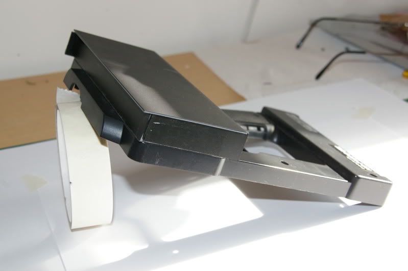 I'll leave it overnight for the solvent to dry, then trim off the excess plastic. The sides are strips of 2mm styrene, the face is 1mm styrene. The face is just there to keep everything square. I'll cut a hole for the display and fit the PCB standoffs, then laminate another sheet of 2mm styrene on top, with a recess to hold the 2mm clear acrylic display cover. |
|
| |
|
| |


 Linear Mode


