| |
| |||||||
 |
| | LinkBack | Thread Tools | Display Modes |
 02-08-2010, 03:01 AM
| #241 | |
| Pebble Pounder Join Date: Aug 2008 Location: Spain
Posts: 103
| Quote:
You can also program it to have front DIG(0% front axle, 0-100% rear axle), fixed rear DIG(0-100% front axle, 0% rear axle). That with de Dual Rates and so. If you explore the programming you can find a lot of possibilities. I have build some of this TXs for friends with 2.2&SUPER (MOA and Dual ESCs). Cheers, Carlos | |

|  |
| Sponsored Links | |
| | |
|
02-08-2010, 07:15 AM
| #242 | |
| Got Worms? Join Date: Jun 2009 Location: Golden, CO
Posts: 6,116
| Quote:
| |
|
| |
|
02-08-2010, 07:26 AM
| #243 | ||
| I wanna be Dave Join Date: Oct 2008 Location: Golden
Posts: 2,588
| Quote:
Quote:
@meao - I was looking at some of the stuff t6config can do, and it's pretty customizable, but I think the dual esc can be set up without any of the programming options. If I used a 5 position rotary switch, I could wire positions 2 and 4 in line with a pot, and have my variable rates right there. There may not be enough space to do that though. ESC Rotary Switch position 1 - front 100%, rear 0% 2 - front 100%, rear variable 0-100% depending on position of pot 3 - front 100%, rear 100% 4 - front variable 0-100% depending on position of pot (can be same or different from the rear variable pot) 5 - front 0%, rear 100% Steering rotary switch Position 1 - Front 100%, Rear 0% (Front only) 2 - Front 100%, Rear -100% (reversed) (4WS) {may be able to just reverse the pot wires to the channel for this part... no mixes needed) 3 - Front 100%, Rear 100% (crab walk) 4 - Front 0%, Rear 100% (Rear only) So this way you could either have it preset to the percentage that seems to work well, or vary it on the spot depending on the climb to fight clod stall. It would be all done through varying the resistance on the channel (moving the endpoint) rather than any mixes, leaving the mixes for rear steer and enabling channel 5 and 6: Mix 1 - VR.A -> Channel 5 - On Mix 2 - VR.B -> Channel 6 - On Mix 3 - Channel 1 -> Channel 6 - Switch A -100 (To reverse the output if you wanted to use mixes.) Switch A - Null Switch B - Can be used for dual rates if needed... At the rx: Channel 1 - Front Servo Channel 2 - Front ESC Channel 3 - Open 3 position channel Channel 4 - Open 3 position channel Channel 5 - Rear ESC Channel 6 - Rear Servo I'm not 100% sure this will all work, as it's just me trying to figure it all out... Hmm... If it works without mixes, someone could probably do the same to a simple TQ4 2.4ghz radio... | ||
|
| |
|
02-08-2010, 07:53 AM
| #244 | |
| Pebble Pounder Join Date: Aug 2008 Location: Spain
Posts: 103
| Quote:
You can configure the VR A or B to actuate like a proportional mix beetween 2 channels. I mean, if your source is channel 2 and the slave one is channel 4, you can increase or decrease "the signal" in the slave channel by the VR A or B. So you can variate this mix "in real time" as you need in each moment. Try it, you'll see how easy it is. Note: My english is not very good, I know | |
|
| |
|
02-08-2010, 07:57 AM
| #245 | |
| Pebble Pounder Join Date: Aug 2008 Location: Spain
Posts: 103
| Quote:
The Steering R.S. will work if you use a dual pole pot(to reverse the rear channel for 4ws). Cheers, Carlos. | |
|
| |
|
02-08-2010, 08:15 AM
| #246 | |
| I wanna be Dave Join Date: Oct 2008 Location: Golden
Posts: 2,588
| Quote:
The steering wheel has 3 tabs for wires, at rest, the resistance between the left and center wire is the same as the resistance between the right and center wire. When you turn the wheel to the left, the resistance between the left and center wire reduces, at the same time the resistance between the right and center increases. What I planned on was at the Crab Walk position, the left pot wire would connect to the right side wire at the channel, and vice versa, so the channel thinks that the wheel is being turned to the opposite side. Your graupner radio works similarily in terms of hardwiring the channel reversing. I think it will work, but I'll have to get the rotary switch to make sure... | |
|
| |
|
02-08-2010, 03:33 PM
| #247 | |
| Got Worms? Join Date: Jun 2009 Location: Golden, CO
Posts: 6,116
| Quote:
| |
|
| |
|
02-08-2010, 05:17 PM
| #248 | ||
| I wanna be Dave Join Date: Oct 2008 Location: Golden
Posts: 2,588
| Quote:
Quote:
| ||
|
| |
|
02-08-2010, 07:23 PM
| #249 | |
| Got Worms? Join Date: Jun 2009 Location: Golden, CO
Posts: 6,116
| Quote:
| |
|
| |
|
02-09-2010, 03:17 AM
| #250 |
| Pebble Pounder Join Date: Aug 2008 Location: Spain
Posts: 103
|
Hi guys, I have found an easy way. Using the Acro type: http://www.youtube.com/watch?v=mT2ArGqp6Ew It's in Spanish, but, you can see on the PC how it works: -Front DIG -Rear DIG -Variable Torque Controller(programmed to +-30% in the rear axle) -and a 5th channel activated. Just change SW B by a 2p2s switch, connecting there the "orginal SW B cables"(the black ones) and using the othe pole to switch the control from channel 3 to channel 2. The SW B is activated as DR. |
|
| |
|
02-09-2010, 07:27 AM
| #251 | |
| I wanna be Dave Join Date: Oct 2008 Location: Golden
Posts: 2,588
| Quote:
Do you have a link to somewhere that explains (even if it's in spanish) how exactly he's got that wired? And how the dr is programmed in the T6Config program? I may have figured it out using the rotary switch method though: My theory on dual esc control It appears though, that the method shown in the video doesn't allow "on the spot variable control," it seems you have to program (through the DR) what percentage you want it to be. With my method (if it works) you can dial exactly what percentage you want with the 5k pot. | |
|
| |
|
02-09-2010, 03:24 PM
| #252 | |
| Pebble Pounder Join Date: Aug 2008 Location: Spain
Posts: 103
| Quote:
It is programmed by a Mix, using the VR A as source, channel 3 as slave and "always ON". The Dual Rate is used to actuate the FRONT DIG. Changing the single pole "interruptor"(ON/ON) by a a dual pole interruptor. 1 pole to activate/desactivate the DR, and the other pole to SWAP the 3rd channel signal beetween 2nd and 3rd channel. So, when you actuate on it, the DR is activated and the signal is swapped from channel 2 to channel 3. Cheers, Carlos. | |
|
| |
|
04-17-2011, 10:46 PM
| #253 | |
| I wanna be Dave Join Date: Feb 2007 Location: South FL
Posts: 3,349
|
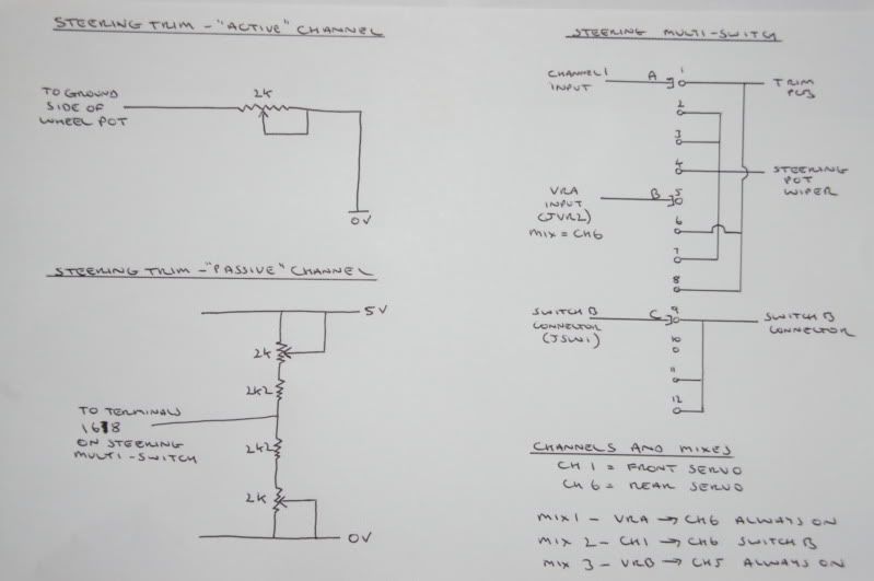
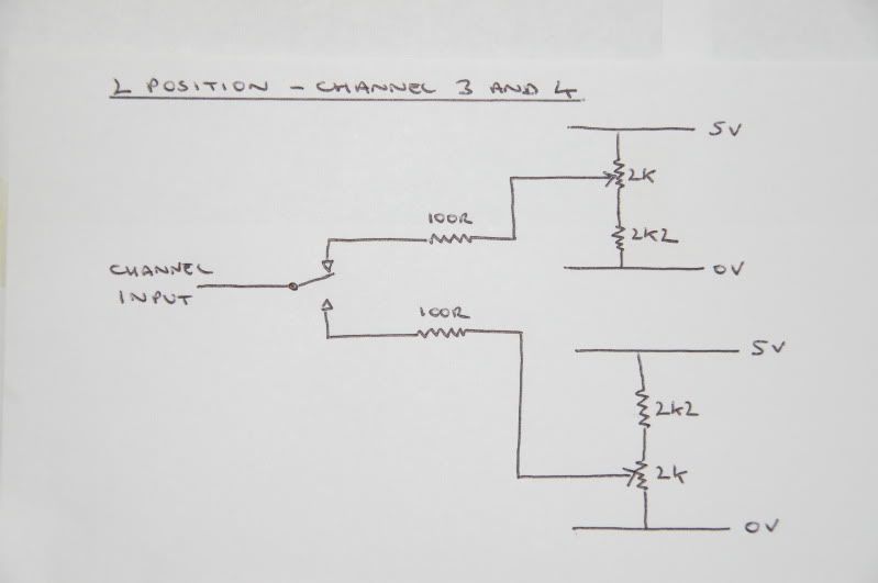
Ok I'm not great at this so lets see if i have this right before I heat up a soldering Iron. I have done the 4cell mod and trimmed the board to fit in my TQ3 case and everything still works. the goal is much like your setup. 4WS via ch1 & ch6 using the rotary switch. then two 3 position switches and one 2 position with trim on ch 1,3,4,5,6 CH1 (center wire ) signal wire goes to pole A CH6 VRA JVR2 signal wire goes to pole B SWB JSW1 any wire goes to pole C terminals 9,11,12 go to the other wire from SWB JSW1? does JSW2 get used at all? should i just remove the switch and connect the shortened wires? Terminals 2,3,4,7 wired together go back to the steering pot signal terminal that was removed for pole A Terminals 1,6,8 are joined together and go to the 2k2 resistors and 2k trim pots (also have 1k pots if those are better ) but I am not sure how to wire that 1 wire to the resistors and trim pots and this is where i get even more lost.. Im not sure how to wire up the trim board at all really. I would like to have the steering trim and to be safe trim and end points on the 3 extra toggle switches as yours is done. also On the 2 way and 3 way switches you have 100R resistors shown. is that for setting end travel like the 470R you previously used? i have both 100R and 470R and wasn't sure what to use sorry for all the questions and thanks in advance for the help Quote:
Last edited by spoo76; 04-17-2011 at 11:03 PM. | |
|
| |
|
04-18-2011, 04:35 AM
| #254 |
| RCC Addict Join Date: Mar 2010 Location: Alburtis
Posts: 1,227
|
This is really cool, but my wife would kill me if I started another project. Maybe I can squeeze it in after we sell our house and our new one is built. Wes |
|
| |
|
04-18-2011, 08:01 AM
| #255 | |
| Got Worms? Join Date: Jun 2009 Location: Golden, CO
Posts: 6,116
| Quote:
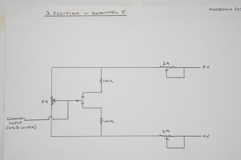
Yes it does seem like you have dechphyered what clockworks was thinking, but i never tried it, because i couldn't make sense out of it. This is kinda what i have been using, its still doesn't work properly though because of analog mixing (just connecting signals together)  Now i have been running a passive trim to each one, instead of having one for all, Also 9, 10, 12 need to connect to swb +v , not 11 470 should be fine for the 3 way switches, this is what i do  clockworks uses those 2k pots for epa's, and 3 pos that 5k pot is trim | |
|
| |
|
 LinkBacks (?)
LinkBack to this Thread: http://www.rccrawler.com/forum/electronics/193303-build-5-6ch-pistol-tx-%24120.html | ||||
| Posted By | For | Type | Date | |
| ZONACRAWLING • Ver Tema - -CRAWLECTRONICS- "Post Oficial" | This thread | Refback | 02-19-2013 05:12 PM | |
| Thread Tools | |
| Display Modes | |
| |


 Linear Mode


