| |
 10-01-2009, 03:48 PM
| #81 |
| Pebble Pounder Join Date: Aug 2008 Location: Spain
Posts: 103
|
GREAT JOB STEVE!!!  I'm very surprised with the TRIMM/EPA board(and very interested A lot of days without a new, and you surpised us with this Board Cheers, Carlos. |

|  |
| Sponsored Links | |
| | |
|
10-01-2009, 05:58 PM
| #82 |
| Rock Crawler Join Date: Feb 2008 Location: UK
Posts: 818
|
The trim/EPA circuits are fairly simple. The hard part was fitting them all on that small PCB. I'll try and get the schematics done at the weekend. I'm working on a 7-segment LED display for the steering modes on my DX6i/KO TX. It'll show "F, 4, C, R", depending on the position of the steering multi-switch. I've got the circuit working, just need to make sure that it works in the Tx. It uses the "ground" switch pole that operates the mixes. I need to check that it doesn't interfere with the operation of the mixes. |
|
| |
|
10-01-2009, 09:10 PM
| #83 |
| Quarry Creeper Join Date: Feb 2009 Location: ewetah
Posts: 315
|
great job, is there a way to make one with 4-5 channels that could control the front and rear escs with mixing? I have a berg and want to run 2 escs and be able to slow down or speed up individually, like the futuba 4pk. what would be a good donor radio for this that I would'nt have to use a usb interface to program, would the dx6 work? thanks Joe
|
|
| |
|
10-02-2009, 01:10 AM
| #84 |
| Rock Crawler Join Date: Feb 2008 Location: UK
Posts: 818
|
The PCB in a DX6 is a bit too big, but the DX6i can be converted - see my thread from a couple of months ago about fitting DX6i electronics in a KO Mars pistol Tx. It's a bit more complicated, as you have to mount the display panel. I've got no experience of dual ESCs, so I'm not sure what control input methods work. You could certainly mix 2 "throttle" channels and control them from one pot, and select between them, using a simpler version of the steering rotary selector switch. The problem comes if you want to use both ESCs at the same time (no problem), but you want to send more power to one axle. You could use "dual rates" for this, but that normally gives you a fixed ratio between the master channel and the slave. Some Tx's have an option for variable rates, usually in helicopter mode, which will allow you to vary the ratio in real time. AFAIK, the DX6i can't do this, but the Turborix can (I think). Your best bet will be to find a stick radio that has all the options you need, then look into modifying it into a pistol case. Maybe ask in the Aircraft/Radios forum on RC Groups. |
|
| |
|
10-02-2009, 09:43 PM
| #85 |
| Quarry Creeper Join Date: Feb 2009 Location: ewetah
Posts: 315
|
Thanks for the info I'll check into some radios and see what i can come up with.
|
|
| |
|
10-03-2009, 07:05 AM
| #86 | |
| Pebble Pounder Join Date: Aug 2008 Location: Spain
Posts: 103
| Quote:
| |
|
| |
|
10-03-2009, 08:09 AM
| #87 |
| Rock Crawler Join Date: Feb 2008 Location: UK
Posts: 818
|
The 7-segment display works fine on the Dx6i/KO Tx - it doesn't interfere with the operation of the steering mixes. Shame it can't be used on the HobbyKing conversion. I'm also removing/relocating some of the switches on the DX6i, to simplify the controls. I'm going to remove the pot controlling the spare channel, just leaving the 3-position switch. I can't think of any use for a variable channel. This will create some space for the display, and some status LEDs for the 2 and 3-position channel, to the left of the steering wheel. |
|
| |
|
10-06-2009, 10:16 PM
| #88 |
| Got Worms? Join Date: Jun 2009 Location: Golden, CO
Posts: 6,116
|
I would like to do this build but put it into a TQ, but the main board is to long, but i thought that if i was to cut the board into 2 sections. these sections is where the input power is and on the other side of it, so split it where that resistor is (green)(i think its called a resistor) but where is the rest of the circuit i see a line leaving but not coming back, hope this makes since if it don't i'll do some photo editing to help
|
|
| |
|
10-07-2009, 12:29 AM
| #89 |
| Rock Crawler Join Date: Feb 2008 Location: UK
Posts: 818
|
You could actually cut off and throw away that part of the PCB. The only things on it are the power switch, battery connector, charging socket and protection diode. Unsolder the left side of the big green resistor, then cut the board right up to where the capacitors are fitted. Solder the negative battery lead to the ground track on the back of the PCB. Connect the positive battery lead to one side of the TQ switch, then from the switch to the free end of the green resistor. |
|
| |
|
10-07-2009, 03:21 PM
| #90 |
| Got Worms? Join Date: Jun 2009 Location: Golden, CO
Posts: 6,116
|
where is the ground (don't know nothing about this PCB stuff) also what do i cut it with
Last edited by losikid; 10-07-2009 at 04:53 PM. |
|
| |
|
10-08-2009, 01:02 AM
| #91 |
| Rock Crawler Join Date: Feb 2008 Location: UK
Posts: 818
|
The ground track is most of the back (green) side of the PCB. If you look at the back, you can see that most of it is covered in green paint. Underneath the paint are the tracks. The ground track covers a large area, the positive and signal tracks are smaller and narrower. You really need a multimeter to check what tracks go where. Before you start modifying PCBs, get a cheap volt/resistance meter. Set the meter to "ohms", and put one probe on the battery ground wire. Put the other probe on various parts of the tracks, making sure that it goes through the green paint. Anywhere the meter shows zero, that's the ground track. You can cut the PCB with a small hacksaw. It's made of fibreglass (GRP). |
|
| |
|
10-13-2009, 08:55 PM
| #92 |
| Got Worms? Join Date: Jun 2009 Location: Golden, CO
Posts: 6,116
|
well i got the power figured out and the size (kinda) but once i connected every thing up i found out that the pots on the trigger and wheel was too small (servo had a small amount of movement) and the TQ isn't very friendly when switching out parts, do you have an idea how to fix this without a new pot, and i noticed that moving my antenna and its module away from the battery's the jittering stopped, maybe this is the problem with your first build
|
|
| |
|
10-13-2009, 11:37 PM
| #93 |
| Newbie Join Date: Oct 2009 Location: Norcal
Posts: 1
|
Have you considered selling these? I'd be interested in buying one. |
|
| |
|
10-14-2009, 12:56 AM
| #94 |
| Rock Crawler Join Date: Feb 2008 Location: UK
Posts: 818
|
I've not really looked at the TQ3, but replacing the pots won't make any difference. I did notice that the wheel movement was very small on the TQ3, compared to the 2 Txs that I've modified. What you need to do is modify the wheel mechanism so that it turns more. If you remove the wheel, there's probably a couple of limiters that restrict the rotation, and a lug on the back of the wheel. Trim the limiters or the lug carefully, but don't remove too much plastic, or the wheel will go "over centre" and feel really weird. You can do the same with the trigger, if there isn't enough movement to calibrate your ESC. I had to cut some plastic from the case, as well as from the limiters, so that the trigger could move further. I assume that you've already adjusted the EPA/Travel Adjust to 120% using the PC software. The jittering problem with my first build was caused by me extending the PC interface wires. Are you mounting the PCB in the standard TQ3 position, directly over the battery holder? |
|
| |
|
10-14-2009, 12:57 AM
| #95 | |
| Rock Crawler Join Date: Feb 2008 Location: UK
Posts: 818
| Quote:
| |
|
| |
|
10-14-2009, 03:22 PM
| #96 |
| Got Worms? Join Date: Jun 2009 Location: Golden, CO
Posts: 6,116
|
Yea i'm doing it over the battery tray and if any one is interested i might build these, but i need to figure out mine first, i'd probably selll them in between 150-200 depending on the price of parts and how custom it has to get
|
|
| |
|
10-14-2009, 03:27 PM
| #97 |
| Pebble Pounder Join Date: Aug 2008 Location: Spain
Posts: 103
|
Hi, Steve. One question about the "trim board", are you using a schematic similar to the Mx3's 3rd channel. Adding the "trimmpot" voltage and eliminating one resistor?. |
|
| |
|
10-16-2009, 12:52 AM
| #98 |
| Rock Crawler Join Date: Feb 2008 Location: UK
Posts: 818
|
Hi Carlos Not sure I understand the question? I'll try and draw the schematic for the trim PCB, then post it here. Steve |
|
| |
|
10-16-2009, 09:44 AM
| #99 |
| Rock Crawler Join Date: Feb 2008 Location: UK
Posts: 818
|
Schematics for the controls and trims: 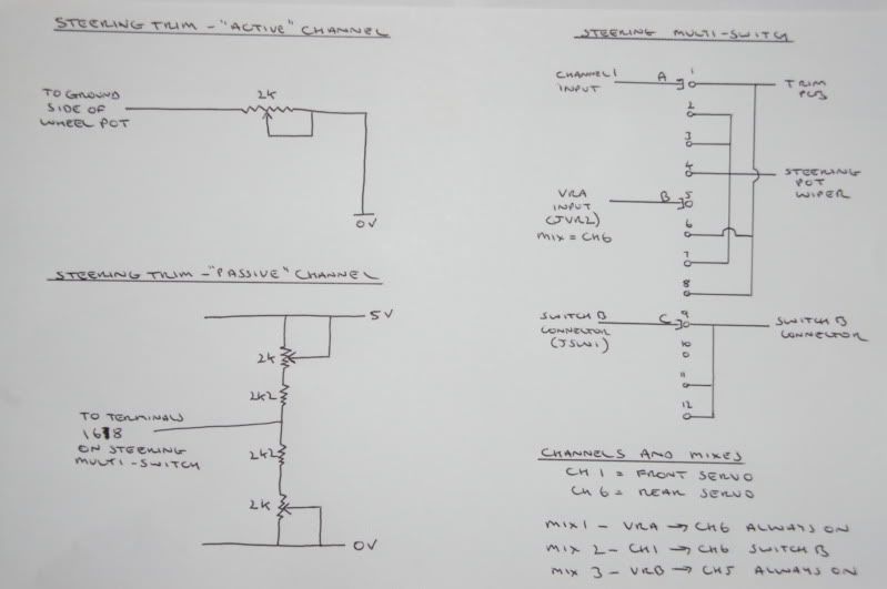 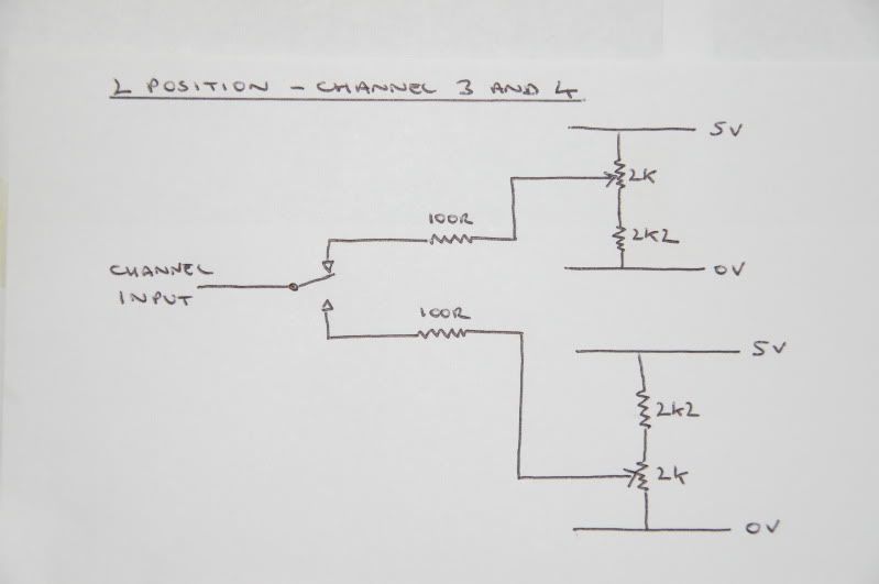 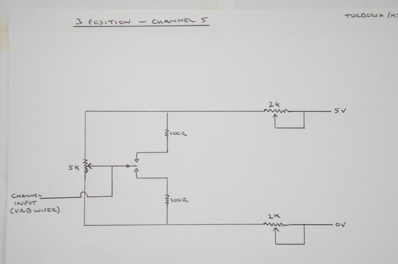 |
|
| |
|
10-16-2009, 10:12 AM
| #100 |
| Pebble Pounder Join Date: Aug 2008 Location: Spain
Posts: 103
|
Hi steve, very good schematics, easy to understand. I'm sure that people will thank this great work you are doing I was refering to this mod: http://www.rccrawler.com/mx3.htm And this schematic:  But I see, you are doing it different, just "trimming to one side"(active channel). I mean, you add a variable resistor between the ground pin of the wheel-pot and the ground in the PCB, isn't it?. Cheers, Carlos. |
|
| |
 |
 LinkBacks (?)
LinkBack to this Thread: http://www.rccrawler.com/forum/electronics/193303-build-5-6ch-pistol-tx-%24120.html | ||||
| Posted By | For | Type | Date | |
| ZONACRAWLING • Ver Tema - -CRAWLECTRONICS- "Post Oficial" | This thread | Refback | 02-19-2013 05:12 PM | |
| |


 Linear Mode


