| |
 10-16-2009, 11:07 AM
| #101 |
| Rock Crawler Join Date: Feb 2008 Location: UK
Posts: 818
|
Hi Carlos For a 3-position switch, that's a good way to trim the centre point. It could be used to trim the "active" steering channel on the Turborix conversion, and also for the "passive" channel. If you need to adjust the centre point of a 3-position switch, and you don't have a pot fitted like in the channel 5 diagram, it would be good to use this method. It gives the same result as the way that I did it, but it might be easier to use for some people. It would be very useful on a non-computer radio. |

|  |
| Sponsored Links | |
| | |
|
10-17-2009, 08:46 PM
| #102 |
| Got Worms? Join Date: Jun 2009 Location: Golden, CO
Posts: 6,116
|
well i just about solder all my channel wires together but i wanted to make sure everything worked before i solered every thing and when i put all my batterys in i never got the led to come on or no signal was being sent to the computer, and there is power being sent to the chip, only visual problems i see is that there is a small chip on the bottom of the led and i have hot glue on the resistor thats going to the chip and alot of hot glue ont the bottom of the pc out chip and its connected ont top of the main pcb where the vr wires are in that gap, did i screw up really bad with that hot glue or is it an easy fix
|
|
| |
|
10-18-2009, 12:50 AM
| #103 |
| Rock Crawler Join Date: Feb 2008 Location: UK
Posts: 818
|
If you didn't get any smoke, chances are you've just missed out a wire or something. If you've got a decent camera, post some close-up photos of the PCB and wiring.
|
|
| |
|
10-18-2009, 10:46 AM
| #104 |
| Got Worms? Join Date: Jun 2009 Location: Golden, CO
Posts: 6,116
|
i have my black wire off my battery tray to the groung track on the pcb and my red wire off my battery tray to a switch then off the switch to the reistor, i put a volt meter to the resistor and the groung track an i've got power to the pcb, then there are those black tower like item (transformer i think) by the resistor and they have alot of heat on the bottom of the pcb when i give it some power, i'll get some pictures up in a little bit
|
|
| |
|
10-18-2009, 12:26 PM
| #105 |
| Got Worms? Join Date: Jun 2009 Location: Golden, CO
Posts: 6,116
| http://picasaweb.google.com/auhutchi...eat=directlink here are a bunch of pics, no wires are hooked up too switches yet excpet my switch a and b all the vr's and channels are loose wires
|
|
| |
|
10-18-2009, 02:05 PM
| #106 |
| Rock Crawler Join Date: Feb 2008 Location: UK
Posts: 818
|
What voltage are you using? Presumably 12v, as you seem to be using all 8 cells in the battery tray. The black components are capacitors, and they shouldn't be hot. Are you sure that the black wire is connected to the ground end of the battery tray, and that you've connected it to the ground track on the PCB? Check this by measuring the resistance between your black wire and one of the black wires that originally went to the pots - it should be zero ohms. The switch wiring looks OK - battery positive to switch to resistor - again, double check that you've actually connected it to the battery positive. If that's all you've got connected, apart from the A and B switches, the next thing to look for is a short circuit, possibly between a red and a black wire that normally goes to one of the pots. Take the batteries out and measure the resistance between the points where you've soldered the 2 wires to the PCB - it should be at least 25 ohms, possibly more. If it's less, you've got a short circuit. |
|
| |
|
10-19-2009, 08:43 PM
| #107 |
| Got Worms? Join Date: Jun 2009 Location: Golden, CO
Posts: 6,116
|
well what you describe is i got a short circut but i see nothing touching, but nothing is touching maybe i melted it with hot glue, and it is on the underneath side of the capacitors that there is a hot little black square and it is hot hot, could this be the problem, also what ohm setting should i use, because i kave to set it to like 20k or 200k to get any reading for short circuits, i was getting like 14 i think,
|
|
| |
|
10-20-2009, 01:45 AM
| #108 |
| Rock Crawler Join Date: Feb 2008 Location: UK
Posts: 818
|
measuring between the plus and ground rails, you'll get some reading. What you are looking for is a dead short. This could be between zero and a couple of ohms, depending on the quality of your meter. Set the meter to one of the lowest ranges - 200 ohm or 2K - to take the measurement. If you are getting a reading of 14, it doesn't sound like a short. Is this the component that's getting hot? The black rectangle with the blue wire across it. 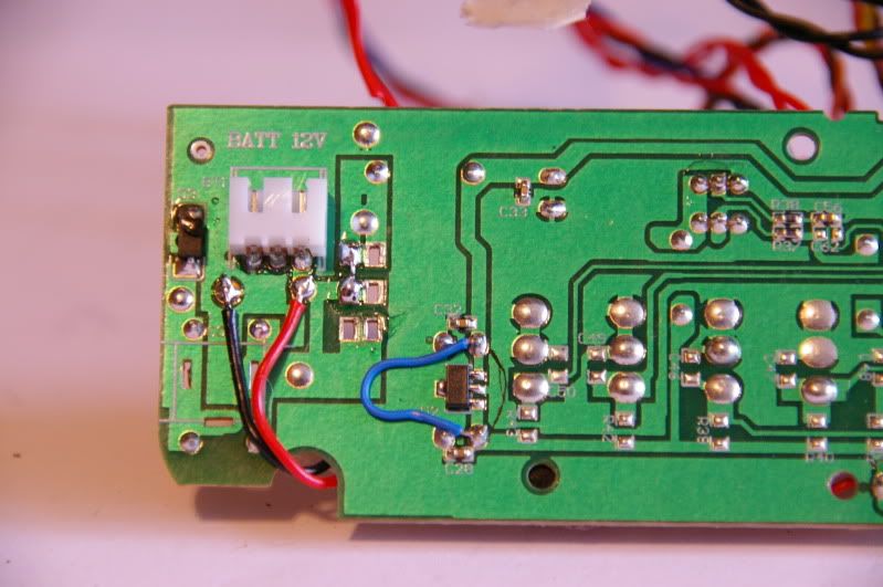 Note that the wire is a modification that I added to make it work on 4 cells. |
|
| |
|
10-20-2009, 06:31 AM
| #109 |
| Got Worms? Join Date: Jun 2009 Location: Golden, CO
Posts: 6,116
|
yea its that black rectangle by the blue wire
|
|
| |
|
10-20-2009, 09:42 AM
| #110 |
| Rock Crawler Join Date: Feb 2008 Location: UK
Posts: 818
|
That component is the voltage regulator. It drops the 12v from the batteries down to 5v for the electronics. It will get warm, but not hot enough to burn your finger. Just above and below the regulator, there are 2 very small brown components, labelled C28 and C32. Set your meter to voltage (the 20v scale is best), connect the batteries and switch on, then measure the voltage between the solder points where C32 is soldered to the PCB. You should get 12v. This proves that the battery is connected up. Now measure the voltage across C28. It should be 5v. This proves that the regulator is working properly. If you've got both of these voltages, chances are you haven't blown anything. Disconnect everything that you've soldered or glued, except for the battery box and power switch. Make sure that all the loose wires are insulated, and switch on. See if you get the LED lit up, and try the PC cable. |
|
| |
|
10-20-2009, 05:54 PM
| #111 |
| Got Worms? Join Date: Jun 2009 Location: Golden, CO
Posts: 6,116
|
i feel stupid right now, i still don't know what happened but i was sitting there screwing with the resistor and all of suddend the light turned green, i can turn the light on and of by moving my positive wire, i think i didn't have a good solder and the hot glue disconnected it, but then why was i getting power to the board, i also just got an idea reading through this thread, since they make a t6 program for like a pda, could we buy a cheap pda for like 30-50 dollars and find a pistol case that can fit the 2.4 tx stuff and a pda screen and its guts or take 2 pistol case and use the back side of one and make it wider in the top so there is more room for the pda guts
Last edited by losikid; 10-20-2009 at 07:07 PM. |
|
| |
|
10-21-2009, 12:55 AM
| #112 |
| Rock Crawler Join Date: Feb 2008 Location: UK
Posts: 818
|
Glad you got the power problem sorted. An easy mistake to make. If you have a "dry" solder joint, you'll get a small current passing through - enough so that you can measure it with a meter, but not enough to make things work. Until you get really good at soldering, it's a good idea to test all your joints by pulling on the wire after the solder has cooled down. I still get the odd dry joint, and I've been soldering for over 30 years. I've not tried the PDA programming option, but I see no reason why building the PDA into the Tx shouldn't work. Thing is, once you've got the radio set up, you don't really need the programming options, unless you want to use it with more than one model. Things like trims and EPA can be done without a PC/PDA by adding trim pots to the Tx. Having said that, it would certainly be a cool mod. You could use the PDA for playing music as well. |
|
| |
|
10-21-2009, 03:46 AM
| #113 |
| Pebble Pounder Join Date: Aug 2008 Location: Spain
Posts: 103
|
I agree, the PDA mod would be cool  |
|
| |
|
10-21-2009, 04:55 PM
| #114 |
| Got Worms? Join Date: Jun 2009 Location: Golden, CO
Posts: 6,116
|
so is hot glue going to be a problem because it worked before i put hot glue around the resistor to hold it in its place from breaking, i think i'm going to start looking for a pda and maybe a small speaker to play music, is there a electrical componet that i could use to make like a lipo cut off, so i can put a small 3s lipo in it, because i'm sure a pda would suck down some juice
|
|
| |
|
10-21-2009, 05:15 PM
| #115 |
| Got Worms? Join Date: Jun 2009 Location: Golden, CO
Posts: 6,116
|
anyone know where the pda program is, i thought it was on this thread but i must of seen it somewhere else
|
|
| |
|
10-22-2009, 01:04 AM
| #116 |
| Rock Crawler Join Date: Feb 2008 Location: UK
Posts: 818
|
Hot glue shouldn't cause a problem. It was probably a bad solder joint, and you disturbed it when applying the hot glue, causing it to fail. Check the mechanical integrity of all your solder joints before applying hot glue, then it should be OK. Rather than fitting a 3s LiPo, do the 4-cell conversion. It's only 2 wires on the PCB, and re-jigging the battery box. You'll get at least 6 hours out of a decent set of AA rechargeable cells. The PDA probably uses a single cell LiPo, so you could add a bigger one for that. This thread http://www.rcgroups.com/forums/showthread.php?t=967207 contains everything you need to know about the Turborix/HobbyKing radios, including using a PDA as a programmer. |
|
| |
|
10-22-2009, 04:36 PM
| #117 |
| Got Worms? Join Date: Jun 2009 Location: Golden, CO
Posts: 6,116
|
i can't get power through the resistor, i don't know why, so can i get some specs so i can order it with some switches i'm getting,
|
|
| |
|
10-22-2009, 05:12 PM
| #118 |
| Rock Crawler Join Date: Feb 2008 Location: UK
Posts: 818
|
The resistor is actually in the circuit to act as a fuse - maybe you blew it? IIRC, that's what Carlos (meao) did a few pages back. You can test it with your meter. With the power switched off and the meter set to the lowest ohms range, it should measure as less than 1 ohm. Alternatively, with the power switched on and the meter set to 20volts, you should have no reading across the resistor. Get the smallest value the store has in stock. The original is 0.1 ohms, but 1 ohm worked for Carlos. I think it needs to be 1 watt |
|
| |
|
10-22-2009, 05:19 PM
| #119 |
| Got Worms? Join Date: Jun 2009 Location: Golden, CO
Posts: 6,116
|
what type of resistor
|
|
| |
|
10-22-2009, 05:39 PM
| #120 |
| Rock Crawler Join Date: Feb 2008 Location: UK
Posts: 818
|
It's a normal metal oxide (metal film) resistor, but it needs to be at least 1 watt, 2 watt if you get one. The standard type are 1/4 or 1/2 watt. The tolerance isn't important. 5%, 10% or 20%, it doesn't matter. Sorry to be a bit vague, but the schematic shows an inductor (coil) in this position, but it's definitely a resistor in real life!
Last edited by clockworks; 10-22-2009 at 05:42 PM. |
|
| |
 |
 LinkBacks (?)
LinkBack to this Thread: http://www.rccrawler.com/forum/electronics/193303-build-5-6ch-pistol-tx-%24120.html | ||||
| Posted By | For | Type | Date | |
| ZONACRAWLING • Ver Tema - -CRAWLECTRONICS- "Post Oficial" | This thread | Refback | 02-19-2013 05:12 PM | |
| |


 Linear Mode


