| |
 09-28-2011, 03:56 AM
| #1141 |
| RCC Addict Join Date: Dec 2009 Location: Newcastle, Australia
Posts: 1,784
|
Ok thanks guys.. So where do yous send yours? Or I should be asking how much life are your getting from yours? Sent to you from my dam phone would you believe! Cheers Dan |

|  |
| Sponsored Links | |
| | |
|
09-28-2011, 06:43 AM
| #1142 |
| I wanna be Dave Join Date: Apr 2007 Location: Arlington, Washington
Posts: 2,303
|
Carter Diamond is where I sent the only one I ever had chip, which happened when a motor run in device surged and sent 9 volts to the lathe...................arm flew off and whacked the bit. I can't remember what they charged. Problem is, Carter Diamond was bought out by a bigger company, so I dunno.....might have to google around, see what you can find. Later EddieO |
|
| |
|
09-28-2011, 09:06 AM
| #1143 |
| owner, Holmes Hobbies LLC   Join Date: Nov 2004 Location: Volt up! Gear down!
Posts: 20,290
|
Diamond is sharpened on a fine al oxide or concrete block with lots of water run on it. The water is key as it makes an abrasive paste. Essentially you would chuck a round bit of concrete or aluminum oxide stone into a lathe and keep cutting into it until the bit was renewed. Then the edge is lapped on aluminum oxide for final edge. Care must be taken to keep the relief angle constant, so the tool will need to be set up properly to grind the right angles into it. Renewing a diamond bit is in no way difficult for a person with motivation to do it. For the time and setup costs, it is just easier to grind HSS bits. HSS is really easy to keep dressed to a razor point, and with proper feed rates and tool shape it cuts copper like butter. Speaking of, butter also makes a good lube for cutting copper Here is a link for some aluminum oxide wheels that can be used for dressing and lapping diamond bits. 60 grit would be appropriate for taking down the bit, and 150 grit would put an edge back on the tool. They must be used wet on diamond. A fine al oxide bench stone would give better control of the edge over using the 150 grit wheel. http://www.sharpeningsupplies.com/No...el-P38C20.aspx Last edited by JohnRobHolmes; 09-28-2011 at 09:40 AM. |
|
| |
|
09-28-2011, 10:33 PM
| #1144 |
| dnf   Join Date: Sep 2009 Location: Under a big fkn rock.
Posts: 1,901
|
anyone have a link to a killer thread linke this one.....on 130 sized/micro/slot motors? I need to take a crash course I have searched some mini sites,but no luck on a real good motor tuning,rebuilding threads Last edited by rock hard; 09-28-2011 at 10:36 PM. |
|
| |
|
09-29-2011, 07:19 AM
| #1145 |
| RCC Addict Join Date: Dec 2009 Location: Newcastle, Australia
Posts: 1,784
|
Thanks for the info John & EddieO  |
|
| |
|
09-29-2011, 02:53 PM
| #1146 |
| Pebble Pounder Join Date: May 2009 Location: Northern Virginia, USA
Posts: 128
|
Will an arm from a closed endbell motor (like those rc4wd motors) fit into a standard 540 can?
|
|
| |
|
09-29-2011, 04:27 PM
| #1147 | |
| I wanna be Dave Join Date: Nov 2010 Location: 07456 N. NJ USofA
Posts: 8,314
| Quote:
| |
|
| |
|
09-30-2011, 02:48 AM
| #1148 | |
| Rock Crawler Join Date: May 2009 Location: Queensland, Australia
Posts: 610
| Quote:
I've done it with Rc3wd and also a couple of stock tamiya 27t silver cans without an issue. Every time, i've done it i've had to adjust the shim stack to get the arm centered in the magnetic field. If you use a Rc3wd motor you will also need to polish both ends of the motor shaft to get it to fit a normal motor bearing. I found that the one i did for a friend was a fly shit bigger than the ID of a standard motor bearing. I carefully put it in my cordless drill and hit it with 2000 grit wet and dry with a drop of bearing oil for lube. Did that until it almost fitted the bearing and then used some metal polish to finish off. Take care doing this, you can nick the comm or bend the shaft if you are heavy handed or not paying attention. Last edited by WIDELOAD; 09-30-2011 at 02:52 AM. | |
|
| |
|
10-01-2011, 01:11 PM
| #1149 |
| dnf Join Date: Sep 2009 Location: Under a big fkn rock.
Posts: 1,901
|
would the offest of the segments compared to the arm,cause heat if motor is runing reversed? So if you swap the poles I never thought it would really hurt. But I can see that some arms the segent if farther left from center than others.And on those arms,reversing poles may be an issue.... thoughts? |
|
| |
|
10-01-2011, 01:32 PM
| #1150 |
| I wanna be Dave Join Date: Apr 2007 Location: Arlington, Washington
Posts: 2,303
|
I guess I am not following what you are asking.... Comm placement is what effects timing on the armature. As long as its a regular armature and the comm slot is centered on the stack (between the stacks on a 5 segment).....so the timing should be neutral on the arm. This was a trick in old stock racing days was looking for arms that had the comm leaning into positive timing or by some cheaters to crank it....just moving the comm a fraction of MM was good for 5 degrees. I have a really trick little tool for measuring comm timing. Was made for me by a guy using EDM...cost was outrageous...but its cool. However on my skewed arms, timing is kinda weird, as techincally it goes from positive timing to negative as the arm moves through the field. Big Jim explained it better, but I cannot find the post anymore......it wasn't as simple really as + to netural to -, but thats the basics of it. Of course, I might just be reading your posts incorrectly, as I am pretty hung over from my birthday party. Later EddieO |
|
| |
|
10-01-2011, 01:44 PM
| #1151 | |
| dnf Join Date: Sep 2009 Location: Under a big fkn rock.
Posts: 1,901
| Quote:
I have one type of arm,and its more than just a touch to the left,it is deffintaly noticable left of center of the stack,I'd say about 2x as far as the other arms. Last edited by rock hard; 10-01-2011 at 02:02 PM. | |
|
| |
|
10-01-2011, 10:17 PM
| #1152 |
| I wanna be Dave Join Date: Apr 2007 Location: Arlington, Washington
Posts: 2,303
|
Comm slot is the term.....it should be dead center for zero timing on a 3 segment motor. In racing, ROAR rules allowed a +/- 2 degree variance in the comm timing. Some of the last 19t and stocks had up to 10 degrees either way. It got to the point where customers were asking for the comm to be measured and written on the dyno sheet.....was annoying. Mod arms seem to be pretty consistent, though there can be variance. I typically will tweak them before they are wound, as I measure them all prior to winding. The main reason I do this is, while positive timing is fine on the forward motor.....its opposite on the reverse....so its negative timing. If you are looking at the comm.....if the slot is to the left, then positive timing.....to the right negative....but thats for a normal rotation motor. I used to have a pic, but can't find it. |
|
| |
|
10-01-2011, 10:57 PM
| #1153 |
| dnf Join Date: Sep 2009 Location: Under a big fkn rock.
Posts: 1,901
|
so on a motor where the arm has pos timing,its not good to swap the end bell or pos/neg wires to revers it's direction like we typically do. If I'm following you correctly,a arm with advanced timing,I should make sure the motor is installed in a manner where pos/negative wires mount on the proper sides of the end bell pos/neg side of enbell and that the pos brush should be centered on the north magnet,so no swapping end bell around. I'm I correct.or confused? |
|
| |
|
10-02-2011, 08:59 AM
| #1154 |
| owner, Holmes Hobbies LLC Join Date: Nov 2004 Location: Volt up! Gear down!
Posts: 20,290
|
When the comm is not perfectly installed, you just have to adjust the endbell to compensate. It doesn't change timing with rotation direction, but it does change the position of true neutral. You can wire up the motor how you wish, and rotate it any direction. Just use an amp meter to find the lowest amp draw and that is true neutral. Advance it in the faster direction with 10% higher no load amp draw and you have a safe timing location. This is all assuming that the brushes don't move in the hoods. In reality there will be a bit of slop and true neutral will not be perfect for both rotation directions. |
|
| |
|
10-02-2011, 11:38 AM
| #1155 |
| dnf Join Date: Sep 2009 Location: Under a big fkn rock.
Posts: 1,901
|
So I can also just forward/reverse till I find zero by sound too right. even though the brush may not be centered on magnet,it will still be aprox zero timing. |
|
| |
|
10-02-2011, 12:44 PM
| #1156 |
| I wanna be Dave Join Date: Apr 2007 Location: Arlington, Washington
Posts: 2,303
|
John are you saying if I am have an arm, with say 10 degrees of timing in it (so slightly left), installed in a can with zero timing on the can, zero on the magnets, a perfectly aligned brushes that it will spin the same forward as it will in reverse? Later EddieO |
|
| |
|
10-02-2011, 04:05 PM
| #1157 |
| RCC Addict Join Date: Jun 2009 Location: QLD, Australia
Posts: 1,512
|
This is far from my specially but I took JRHs post as, to compensate for a arm with +10 timing, you would put your can at -10 timing, which should be the lowest amp draw? Kieren Last edited by Aussie Nerd; 10-03-2011 at 02:50 PM. |
|
| |
|
10-03-2011, 08:13 AM
| #1158 | |
| owner, Holmes Hobbies LLC Join Date: Nov 2004 Location: Volt up! Gear down!
Posts: 20,290
| Quote:
| |
|
| |
|
10-11-2011, 03:54 PM
| #1159 |
| RCC Addict Join Date: Jun 2009 Location: QLD, Australia
Posts: 1,512
|
In case anyone is wondering here's some pictures of Eddie's new stickers... 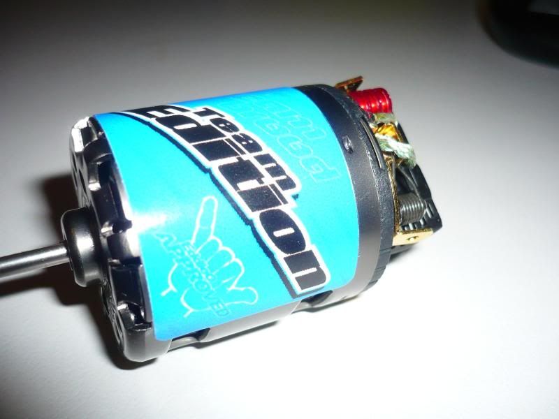 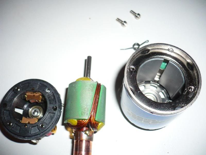 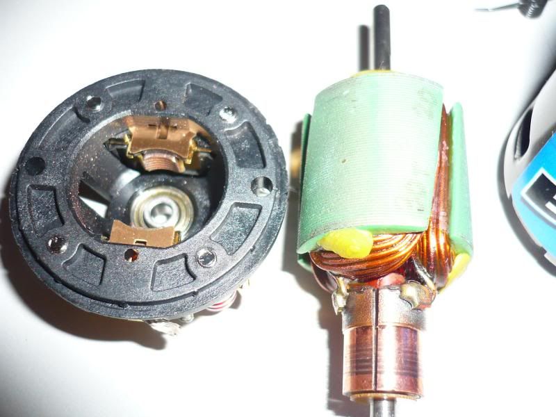 Kieren (sorry John, I couldn't resist...) |
|
| |
|
10-12-2011, 07:49 AM
| #1160 |
| Rock Crawler Join Date: Jul 2010 Location: St. Albans
Posts: 507
|
^^^ Thats purrrdy I have a few arms laying around and they say 11x3 and 12x2 are these equal to a 33t and a 24t. |
|
| |
 |
 LinkBacks (?)
LinkBack to this Thread: http://www.rccrawler.com/forum/electronics/223989-cutting-motor-commutator-motor-tweaks.html | ||||
| Posted By | For | Type | Date | |
| Hiilimoottorin kunnostaminen | This thread | Refback | 10-04-2011 03:19 PM | |
| |


 Linear Mode


