| |
 01-12-2013, 07:01 PM
| #1 |
| I wanna be Dave Join Date: May 2007 Location: Vancouver, BC
Posts: 2,379
|
This will show you how to wire some LEDs to light add some light to your rig. Two bright red LEDs are going to be wired to a plug that you can connect to your receiver to power them up. The plan is to end up with a servo plug going to a length of wire to an LED, then another length of wire to the other LED. These could be installed as a pair of brake or tail lights, or use white LEDs and you could have head lights. For some, this is very basic stuff. For others, I hope this helps answer some questions and encourages you to build your own set of lights! How to wire LEDs An overall view of the materials to be used. Side cutters, needle nose pliers and wire strippers. Two lengths of stranded wire (I think it is 22 gauge) that I recycled from an old network cable. Two LEDs Two 150 ohm resistors Some heat shrink A servo cable cut from an old servo  The LEDs need a resistor to limit the current flow or you risk burning them out or limiting their life. The two resistors shown here are 150 ohm (colour code: Black, Green, Brown, Gold). I will describe how I came to choose this resistance value in another post. LEDs are polarity sensitive devices. This means they will only pass current flow in one direction. The LEDs have a few ways of telling you the polarity of their leads. There will be one lead shorter than the other, and that one is negative. Often there will be a flattened area near the leads and that also indicates the negative lead. I have clipped the negative lead of the upper LED and one end of each resistor.  Here you can see that the upper LED has been soldered to one of the resistors. To do this, I first tinned the areas I want to solder and then held them together and added a little heat until the tinned bits flowed together. If you are wondering if these parts are heat sensitive, the answer is yes. The resistors can tolerate the heat well, but be quick on the LED. A good idea is to hold the LEDs lead with needle nose pliers right close to the LED body. This will help keep the heat from passing into the LED.  Both LEDs with a resistor soldered to their negative leads. The resistor is bent out like that to stop it from rolling over before I took the photo.  Prepping the wire for soldering... I've decided that the grey will be negative and the brown will be positive. The wire length has been cut and the insulation has been stripped to match the components to be soldered. Again, tin the wires before soldering to make things easier.  Notice that because of the way the components are placed, even if the leads are pinched together, there won't be a short circuit - at least, it helps to minimize the risk. Better yet would be to place heat shrink over one of the wires but as you will see later, I'm doing it differently.  Prepping the next set of connections. The wires are cut to length, stripped and twisted together.  Tin the wires and cut the ends off cleanly.  The double wires make things a little bulky, but it will work out.  So far, so good.  Make use of the old servo cable.  The signal wire in this cable serves no purpose for the LEDs so it gets snipped right next to the plug and then peeled right off.  Prep the wires for soldering. Remember that grey is negative. Don't forget about heat shrink (yes, I'm using it here). Also note how the wire lengths are staggered to help reduce the chance of shorts.  Slide the heat shrink onto the wire before you solder that connection (I still forget to do that sometimes!). In this connection, I have slid the thin heat shrink over the grey wire only and the thick heat shrink is slid over both wires. Slide the thin shrink over the soldered connection and shrink it. Then slide the thicker shrink over both the thin shrink and the other connection.  Heat shrink is cut to length to cover up the LEDs and resistors. This size of heat shrink won't easily fit over the LED so I stretched it a little wider by sliding it over my pliers and opening it slightly.  A coat of liquid electrical tape or plasti dip is how I have chosen to insulate around the resistor and LED junction before the heat shrink goes on.  Heat shrink in place and showing off some light!  The completed LED string. Shown next to a Remote Switch For LED Lighting that could be used to remotely operate the lights. Happy Soldering! Last edited by heyok; 11-07-2017 at 03:50 PM. |

|  |
| Sponsored Links | |
| | |
|
01-12-2013, 07:13 PM
| #2 |
| Rock Crawler Join Date: Jan 2009 Location: Boise
Posts: 604
|
Looks good thanks for the how to. Sent from my SGH-T769 using Tapatalk 2 |
|
| |
|
01-12-2013, 07:18 PM
| #3 |
| RCC Addict Join Date: Oct 2009 Location: In the mancave...
Posts: 1,038
|
i was always under the impression that the resistor is to be on the positive side of the led, as to limit the current. good to know. thanks.
|
|
| |
|
01-12-2013, 07:24 PM
| #4 | |
| I wanna be Dave Join Date: May 2007 Location: Vancouver, BC
Posts: 2,379
| Quote:
 | |
|
| |
|
01-12-2013, 07:38 PM
| #5 |
| RCC Addict Join Date: Oct 2009 Location: In the mancave...
Posts: 1,038
|
cool thanks, a buddy of mine just gave me a bunch of leds and resistors today. im trying to learn all of this so as to not have to pay for something i can do myself. im trying to figure out how to read the colors on the resistors right now. but i am scratching my head lol. they are blue in color, with four bands, brown, brown, brown, blue. though, i found a resistor calculator online, but dont know what is the starting band, the brown or the blue.
|
|
| |
|
01-12-2013, 07:48 PM
| #6 |
| I wanna be Dave Join Date: May 2007 Location: Vancouver, BC
Posts: 2,379
|
Hope it helps you! I can read the 5% type resistor colour codes without thinking about them but you probably have a 1% resistor there and I'm not sure how to read it. Found this: Resistor color code calculator - 3, 4 and 5 band resistors Entered in your colours but it didn't like them. I always grab an ohmmeter when in doubt. |
|
| |
|
01-12-2013, 08:10 PM
| #7 |
| Rock Crawler  Join Date: Feb 2009 Location: Wrightstown
Posts: 960
|
How do you come up with the ohm amount for the voltage you are using?
|
|
| |
|
01-12-2013, 08:23 PM
| #8 | |
| I wanna be Dave Join Date: May 2007 Location: Vancouver, BC
Posts: 2,379
| Quote:
You need to know a couple of things about your LED. The amount of current it likes to work with and it's forward voltage. Both of these specs are usually easy to find out as they are often written right on the package or maybe you can look up a spec sheet. Or, you can memorize a couple if common amounts. Generally, the bright LEDs are looking for 20mA of current. If it is a bright red or a white LED, the forward voltage is often 3 volts. I like to power LED lighting from the receiver so in most cases that is a maximum of 6 volts. To find the value of the resistor needed, Ohm's law tells us: Resistance = Voltage / Current So far we know that the current is 0.02 amps We know that the voltage at the supply is 6 and that the voltage across the LED is 3, therefore the voltage across the resistor we are coming up with is 6 - 3 = 3 volts. Now we plug these numbers into the equation: Resistor = 3/0.2 = 150 ohms There's a cool online tool for doing this: LED calculator for single LEDs If you are using the run of the mill, not very bright LEDs, these are the voltage drop that I seem to run into is about 1.7 volts These LEDs often want about 10mA max. Hope that helps! | |
|
| |
|
01-12-2013, 08:31 PM
| #9 |
| Rock Crawler Join Date: Feb 2009 Location: Wrightstown
Posts: 960
|
That helps a lot, thanks. One more question. Is there a limit on how many LED's in a string before there is a voltage drop that would change things. Excellent write up! |
|
| |
|
01-12-2013, 08:32 PM
| #10 |
| RCC Addict Join Date: Oct 2009 Location: In the mancave...
Posts: 1,038
|
heres what he gave me. the top two are smaller than the bottom two. the small ones, left to right are, brown, red, blue, white, brown. the larger ones, left to right are, blue, brown, white, brown, brown. sorry about the misleading colors before. im color blind. had to have the wife tell me what the colors actually are. here's a pic. i appreciate the help. apologies for cluttering up the thread 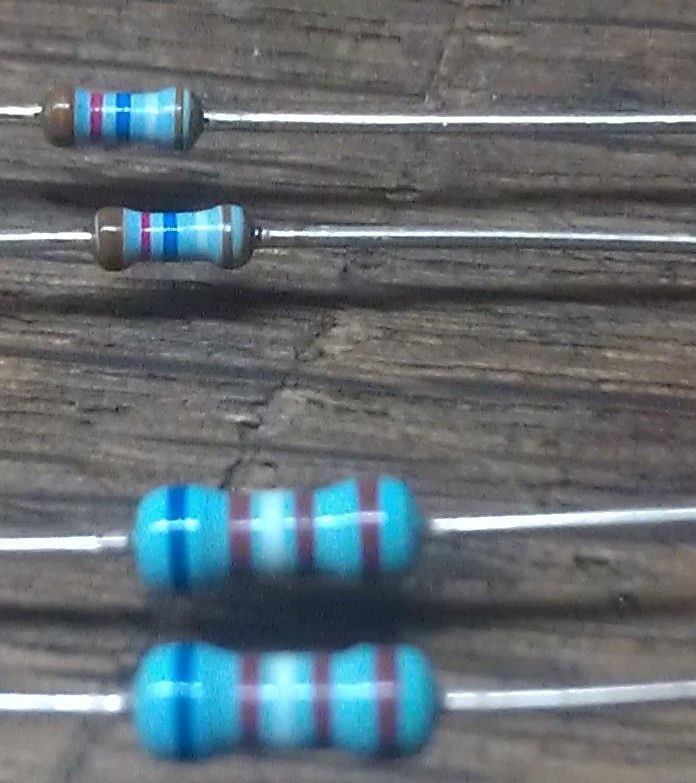 |
|
| |
|
01-12-2013, 09:50 PM
| #11 | ||
| I wanna be Dave Join Date: May 2007 Location: Vancouver, BC
Posts: 2,379
| Quote:
It depends on the quality of the BEC that is supplying the voltage. An easy answer is: It would take a lot of LEDs. The BEC built into a speed control is probably good for 3 amps. You would need 150 LEDs running at 20mA to use 3 amps of current. Let's say you have what some would consider a lot of LEDs. How about 20? 20 LEDs @ 20mA = 400mA ( that's 0.4 amps for those that aren't sure). Not much of a load at all! Quote:
The other is 6.19K ohms. Still, best to check with a meter! | ||
|
| |
|
01-12-2013, 10:38 PM
| #12 |
| RCC Addict Join Date: Oct 2011 Location: British Columbia
Posts: 1,487
|
Great write-up, Al. Very well explained. |
|
| |
|
01-22-2013, 04:56 AM
| #13 |
| Rock Stacker Join Date: Apr 2009 Location: brisbane, Australia
Posts: 67
|
Great write up heyok, you are going to make me go and buy some stuff now. Is there different L.E.D.s available? As in brightness?
|
|
| |
|
01-22-2013, 06:08 AM
| #14 | |
| I wanna be Dave Join Date: May 2007 Location: Vancouver, BC
Posts: 2,379
| Quote:
Yes, there are different brightness LEDs available. There are also different dispersion angles and that will make them appear brighter or dimmer, as the more narrow the beam, the brighter they will seem. If you have a bunch of the same LED and want to have some dimmer than the others, put a larger value resistor in series with it. For example, on my brake light controllers, the brakes are dimly lit when the brakes are off and I do that with a 1K ohm in series with the LED and when they are bright, a 150 ohm resistor is used. | |
|
| |
|
01-22-2013, 06:38 AM
| #15 |
| Quarry Creeper Join Date: Oct 2010 Location: Hendersonville
Posts: 209
|
Awesom write-up, HeyOK! Do you have an tricks for making the brake lights "brighter only when using the brake? How is that tied into the esc control? |
|
| |
|
01-22-2013, 06:45 AM
| #16 |
| I wanna be Dave Join Date: May 2007 Location: Vancouver, BC
Posts: 2,379
|
Thanks. I do have some tricks for making brake lights, but it involves sending me $ These are brake light controllers that I have built. The "trick" involved is that they look at the servo signal that is going to the ESC and determine what is happening, then it outputs power to various pins that you can tie LEDs to. I make several versions so you can have just basic brakes or more things if you need them. Just the Brakes - Brake Light output only Brake Light Controller with Head Light Output Brake, Reverse and Driving Light Controller 3Rd Brake Light Controller (and more) |
|
| |
|
01-22-2013, 08:40 AM
| #17 | |
| Rock Stacker Join Date: Apr 2009 Location: brisbane, Australia
Posts: 67
| Quote:
| |
|
| |
|
01-22-2013, 08:58 AM
| #18 |
| I wanna be Dave Join Date: May 2007 Location: Vancouver, BC
Posts: 2,379
|
Have a look at an electronics supplier. For example, I buy a lot of my supplies from DigiKey Electronics - Electronic Components Distributor Use their search tool to find: LEDs - Discrete click on the result and you will see a big grid of parts with vertical columns for each spec. Of interest would be the "Viewing Angle" (you might have to scroll your view to the right to see all the columns). Also check out "Millicandela Rating" as that is the brightness measurement. Actually, if you find a vendor that is selling LEDs and they list them as Bright, you probably can't go far wrong. If you want to be quite careful in your selection, look at all the specs shown when you search from an electronics component supplier and you can really know what you are getting (if you can make any sense of what the stuff is about). Some thing to be aware of is that you likely want "Through Hole" (that is in the Mounting Type column) type parts rather than surface mount items. Good luck! I will help if I can, but some of the stuff is pretty esoteric. |
|
| |
|
01-22-2013, 09:24 AM
| #19 | |
| Fan of wheelspeed Join Date: Jun 2011 Location: Southern IN
Posts: 3,369
| Quote:
Ive got several kits on their way to me now. My LED kits with Heyoks controllers would be one hell of a combination I am a huge fan of Heyoks winch controllers. Ive owned a few of them and they provide non-stop service. Heyoks electronics are second to none. The LED kits I sell are rated from 5v all the way up to 12v.
Last edited by Hoosierdady; 01-22-2013 at 01:15 PM. | |
|
| |
|
01-22-2013, 12:23 PM
| #20 |
| RCC Addict Join Date: Dec 2011 Location: Raleign
Posts: 1,439
|
So, for a power supply scenario, is it best to just assume 5v from the ESC's BEC? I was wondering because I wast thinking about getting one of your "bypass" kits where I can run the LED's off of a separate battery at say 3S. The problem though is that the voltage starts off high and then trickles down to a lower voltage and then you'd need to think about sizing resistors for higher voltage and then just let them dim out as battery runs down. I'm really looking at about 20 or so LED's total and now I'm thinking that I can just plug them into the RX with the right resistors hooked up as it won't be pulling more than .4a with that many LED's. Ok, so having typed all of this, I've convinced myself just to plug them directly into the RX and use BEC voltage to drive things. |
|
| |
 |
| Tags |
| led, tutorial, wiring |
 How to wire LEDs - Similar Threads
 | ||||
| Thread | Thread Starter | Forum | Replies | Last Post |
| Wire for LEDs. | Mirage | Electronics | 3 | 03-16-2012 07:59 PM |
| Easiest way to wire LEDs in body | AdverseCity | General Crawlers | 3 | 01-22-2012 09:03 PM |
| little help with leds please!!! | lordjasper1988 | Losi Micro-Rock Crawler | 5 | 03-09-2011 05:14 PM |
| Lipo wire smaller than ESC wire..problem? | solomon7 | Electronics | 3 | 03-27-2008 08:45 PM |
| how do I wire red LEDs so it will light up during braking? | ussprinceton2004 | Newbie General | 0 | 03-07-2008 05:33 PM |
| |


 Linear Mode


