| |
| |||||||
 |
| | LinkBack | Thread Tools | Display Modes |
 09-22-2006, 02:56 AM
| #1 |
| R.I.P. Chip   Join Date: Jan 2004 Location: The Crawler State
Posts: 13,938
|
Thanks to roktoy for writing our newest tech article, how to add Independent rear steer to your MX-3. http://www.rccrawler.com/mx3.htm |

|  |
| Sponsored Links | |
| | |
|
09-22-2006, 12:18 PM
| #2 |
| I wanna be Dave Join Date: May 2005 Location: Anchorage, Alaska
Posts: 2,048
|
Very nice.... Time to crack open my radio!
|
|
| |
|
09-22-2006, 01:18 PM
| #3 |
| Quarry Creeper  Join Date: Jul 2006 Location: N. Phoenix
Posts: 440
| |
|
| |
|
09-22-2006, 02:15 PM
| #4 |
| MWRCA'er  Join Date: Apr 2004 Location: Machesney Park IL
Posts: 3,995
|
Wow, that took sometime. |
|
| |
|
09-24-2006, 12:33 AM
| #5 |
| RCC Addict Join Date: Apr 2005 Location: Seattle
Posts: 1,437
|
Funny thing is, I was just reading the TQ3 thread and wondering if it was do-able to my MX-3... off to read the how-to!
|
|
| |
|
09-24-2006, 12:40 AM
| #6 |
| RCC Addict Join Date: Apr 2005 Location: Seattle
Posts: 1,437
|
Hopefully Roktoy is following this thread... How does the radio handle EPA for the modified channel? Is it the same as before, just a 3 position switch instead of 2 now? |
|
| |
|
09-24-2006, 09:08 AM
| #7 |
| Rock Crawler Join Date: Aug 2005 Location: White Lake
Posts: 764
|
Really great artical, I might have to crack open my MX3.
|
|
| |
|
09-24-2006, 01:12 PM
| #8 |
| Rock Crawler Join Date: Aug 2004 Location: Saugus
Posts: 544
|
Thanks for the great write up! Time to steal my sister's MX3. |
|
| |
|
09-24-2006, 02:04 PM
| #9 | |
| Dirt Addict   Join Date: Jan 2004 Location: Stumblin' thru the parking lot of an invisible 7-Eleven
Posts: 1,053
| Quote:
You can see more info in the MX-3 manual here: http://www.airtronics.net/MX-3%20Manual%20Web.pdf Jay | |
|
| |
|
09-29-2006, 02:15 PM
| #10 |
| Newbie Join Date: May 2006 Location: Victoria BC
Posts: 35
|
Just finished the mod+trim pot and it works great. Best $8 spent.
|
|
| |
|
09-29-2006, 06:50 PM
| #11 | |
| Dirt Addict Join Date: Jan 2004 Location: Stumblin' thru the parking lot of an invisible 7-Eleven
Posts: 1,053
| Quote:
Jay | |
|
| |
|
10-08-2006, 09:08 AM
| #12 |
| I wanna be Dave  Join Date: Jan 2006 Location: Iowa, the antirecreation state!
Posts: 2,227
|
Who's done this with more pictures and less technical? I can't get mine to work right yet. Can't get the switch wired correctly or something. THat part of the right up is a little vauge. I guess the schematic shows it but some pics would be better for us simpltons.
|
|
| |
|
10-08-2006, 04:39 PM
| #13 |
| Dirt Addict Join Date: Jan 2004 Location: Stumblin' thru the parking lot of an invisible 7-Eleven
Posts: 1,053
|
Which stage are you trying to do and what part is unclear in the description?....maybe I can help. Jay |
|
| |
|
10-08-2006, 07:00 PM
| #14 |
| I wanna be Dave Join Date: Jan 2006 Location: Iowa, the antirecreation state!
Posts: 2,227
|
Wiring circuits for dummies 101 would help me too. Some pics of the switch wired in. I'm using two momentary on push instead of one swing switch. Same principal just 2 switches instead of one. I have everything soldered for the 1st stage on the board. Just some snap shots of the switch wired in would be great. Thanks Jay.
|
|
| |
|
10-08-2006, 07:02 PM
| #15 |
| RCC Addict Join Date: Apr 2005 Location: Seattle
Posts: 1,437
|
That's not a terrible idea. I am still waiting to do this, may be in more of a hurry if I get my Hi-Lift sooner, but it would be easy to operate like that.
|
|
| |
|
10-08-2006, 10:09 PM
| #16 |
| Dirt Addict Join Date: Jan 2004 Location: Stumblin' thru the parking lot of an invisible 7-Eleven
Posts: 1,053
|
Maybe this will help. Stage 1 wiring..... UPDATED 10/10 TO INCLUDE 5V WIRE. Jay Last edited by roktoy; 10-10-2006 at 08:44 PM. |
|
| |
|
10-10-2006, 06:21 PM
| #17 |
| MWRCA'er Join Date: Apr 2004 Location: Machesney Park IL
Posts: 3,995
|
I can't get it to work right when I flip the switch the servo just hums. Here is how I have it wired. The black wire goes to the node, the green wire goes to the center terminal where the original switch used to be. I've reviewed your diagram several times. 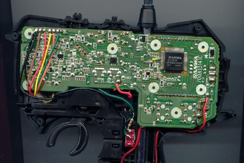 Last edited by Mnster; 10-10-2006 at 06:23 PM. |
|
| |
|
10-10-2006, 07:00 PM
| #18 |
| I wanna be Dave Join Date: Jan 2006 Location: Iowa, the antirecreation state!
Posts: 2,227
|
There you go. That's more better. I'll let you know. Thanks Jay.
|
|
| |
|
10-10-2006, 08:33 PM
| #19 |
| Dirt Addict Join Date: Jan 2004 Location: Stumblin' thru the parking lot of an invisible 7-Eleven
Posts: 1,053
|
Check the voltages. You should see ~2.5V with the switch in the center (open) position which should command the servo to its center position.....lemme know what you find. Jay |
|
| |
|
10-10-2006, 08:38 PM
| #20 |
| Dirt Addict Join Date: Jan 2004 Location: Stumblin' thru the parking lot of an invisible 7-Eleven
Posts: 1,053
|
Ok......sorry guys....I found an error in the Stage1 schematic. You need to wire the other end of the switch to 5V as shown here in the corrected drawing. Let me know if you have problems with this. I apologize for the error. Jay Last edited by roktoy; 10-10-2006 at 08:41 PM. |
|
| |
|
| |


 Linear Mode


