| |||||||
Loading
 |
| | LinkBack | Thread Tools | Display Modes |
| |||||||
 |
| | LinkBack | Thread Tools | Display Modes |
| | #1 |
| Quarry Creeper Join Date: Dec 2009 Location: West Alabama
Posts: 420
|
First off let me start by stating a few things: 1. This is NOT done in an attempt to take away from whats already available from our excellent RCC vendors. 2. I am NOT a vendor, nor plan to be. I dont have the time 3. I am NOT offering these up for sale per #2 above. In looking to get the most from the steering servos in my 3 rigs without burning up the receivers, I knew I would need a Rx bypass in each rig. Yes, there are several out there readily available. Where's the pleasure in saying "I bought that." So I dug about for some supplies, and placed an order. All materials used come from Hansen Hobbies. Parts that were used. 0.1" servo strip PCB (#HH-SC_PCB_PT1INSS) 2 per pack. 1x Gold double row right angle header 80pin (#HH-PT1in_DRRAH80 ) 1x 8in servo lead, 22AWG & Universal Conn (#HH-LEAD_DX22-08 ) 1x Step 1. Using pliers, snap off 3 segments (as one piece) of the double row header. 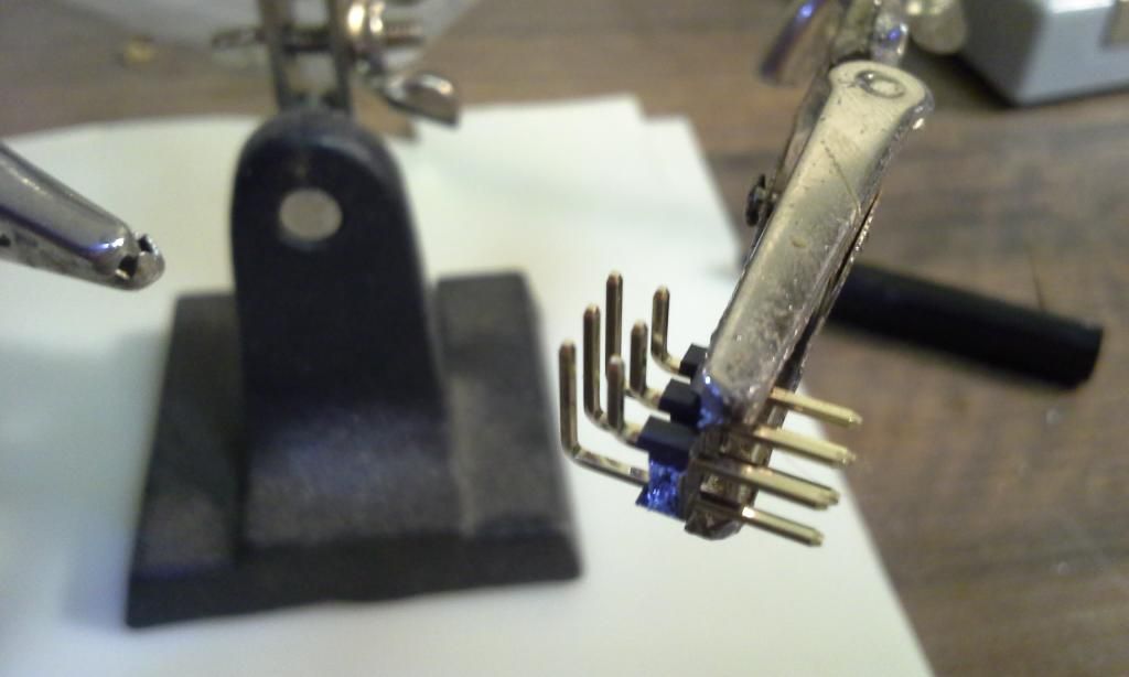 Step 2. With the header in your 3rd hand (or whatever!), line up and rest the PCB strip over the 90° pins. Then solder them up. (I used the smallest tip I have for my iron, and I could have backed off the temp a bit.) 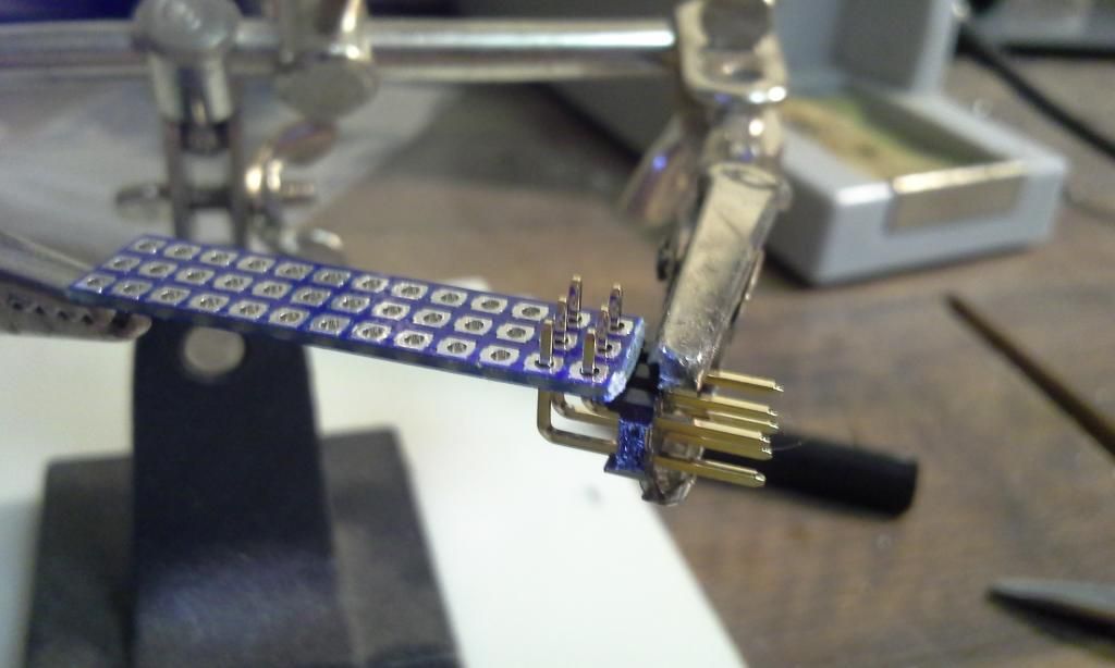 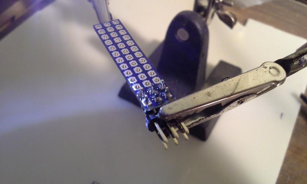 Step 4. Determine the length of the lead. Separate, strip, and tightly twist the strands of the signal and ground leads (I cut the power off short of the stripped segment as to not contact the PCB when attached.) Pass the signal and ground through the holes of the PCB, and secure with 3rd hand. (signal/ground alignment on board will determine which way your BEC and servo will plug in, so keep that in mind). After placing the signal and ground through the board, I tinned the strands and moved my heat down to the board to secure them. Once secured, a sturdy pair of scissors can be used to separate your bypass from the unused portion of the PCB. 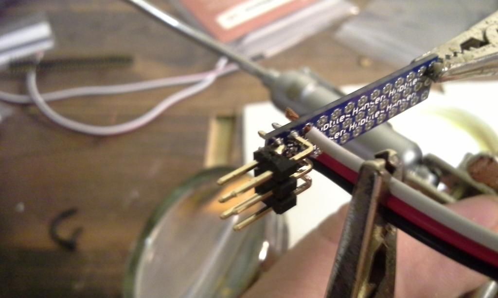 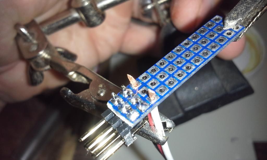 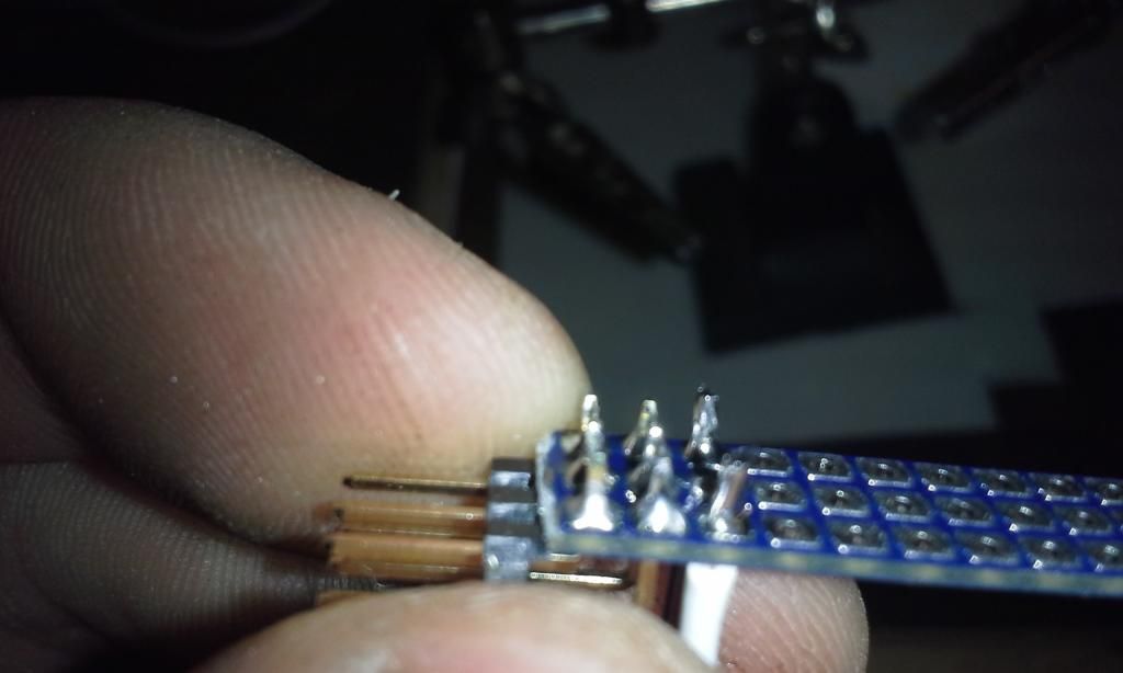 Step 5. I clipped the ends of the pins and strands to smooth things up a bit. A light hit with a dremel would work. I plugged in my BEC and servo, slipped on some heat shrink, and thats that. 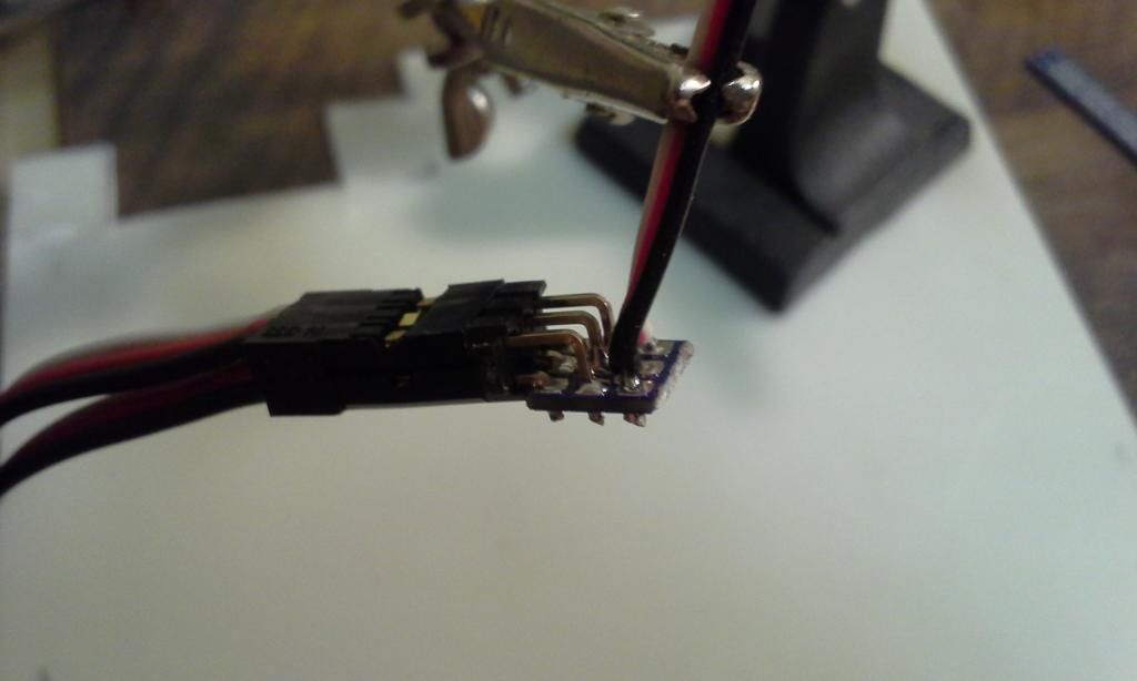 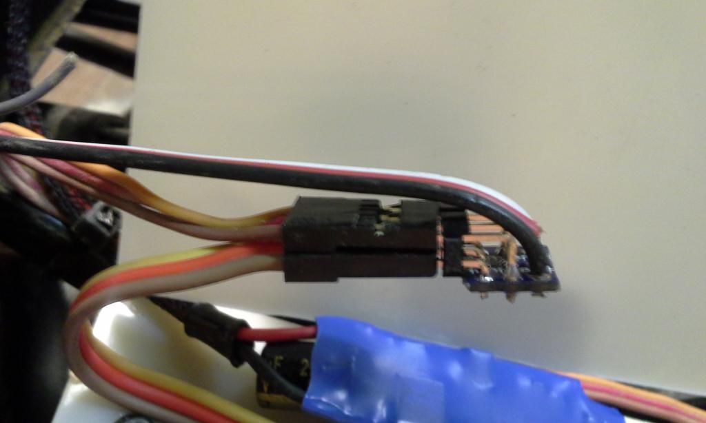 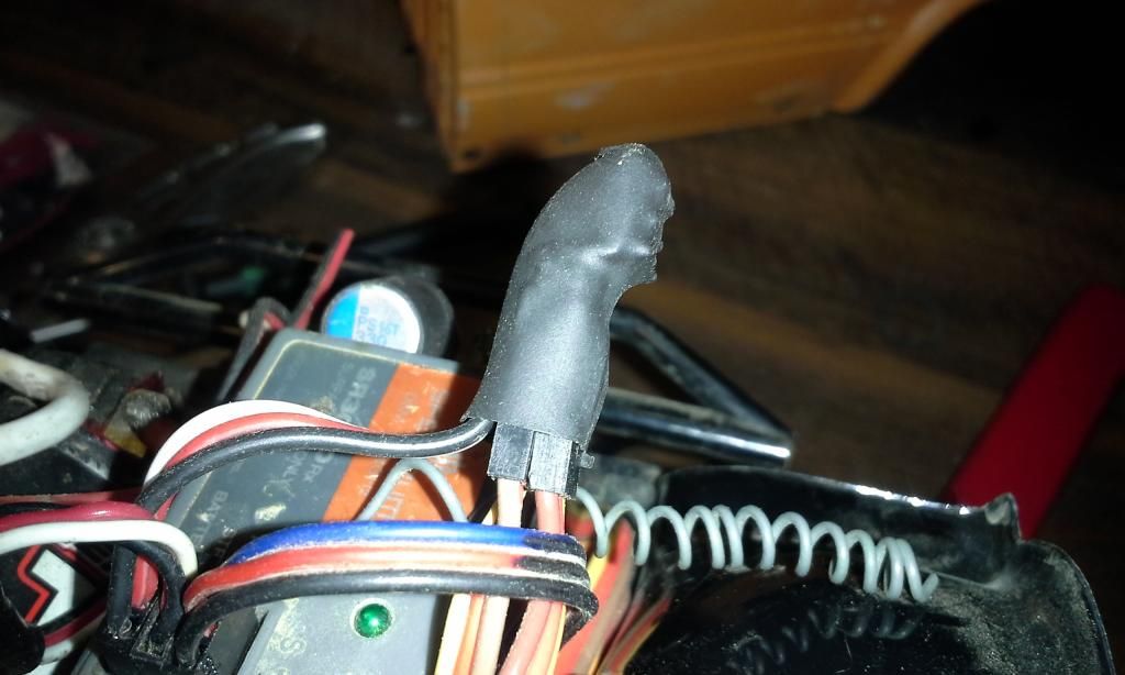 Last edited by nharkey85; 10-01-2014 at 10:07 PM. |
| |  |
| Sponsored Links | |
| | #2 |
| Quarry Creeper  Join Date: Jan 2007 Location: Raleigh
Posts: 361
|
Great job. It looks like it helped clean up some wiring too.
|
| |  |
 |
 Homemade Rx Bypass (PCB) - Similar Threads
 | ||||
| Thread | Thread Starter | Forum | Replies | Last Post |
| pcb question | jenijohnk | Losi Micro-Rock Crawler | 4 | 01-12-2014 12:33 PM |
| Pcb area? | coty41 | Florida | 7 | 09-23-2013 07:37 PM |
| Nuked PCB | Black Rock | Losi Micro-Rock Crawler | 4 | 05-05-2012 10:08 AM |
| anybody in the PCB area?????? | longviewskyline | Florida | 3 | 08-04-2009 08:09 PM |
| PCB this wkn | TRACE | Florida | 1 | 07-14-2009 08:59 AM |
| Thread Tools | |
| Display Modes | |
| |