| |
| |||||||
 |
| | LinkBack | Thread Tools | Display Modes |
 06-13-2009, 02:15 AM
| #1 |
| Newbie Join Date: Aug 2007 Location: Santa Cruz
Posts: 36
|
Hey all, Just wondering if anyone has tried this gear placement before for higher clearance? May try making an axle like this over the summer. It seems like there would be higher ground clearance. But axle gear reduction would be sacrificed and the axle would become more complicated. The ring gear would also have to be small enough so it does not just out far enough from the axle to make it hang up on rocks. Just for reference the bottom big gear would be a ring gear and would be at bottom of the axle parallel to the ground and the two smaller gears a pinion gear but unfortunately i cant do those types of gears in solid works. Ill try to make a more detailed solid works set up later. 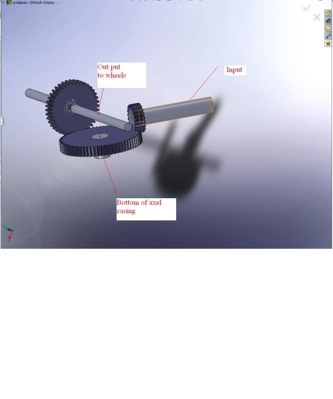 |

|  |
| Sponsored Links | |
| | |
|
06-13-2009, 04:14 AM
| #2 |
| Quarry Creeper Join Date: Jan 2009 Location: Hagerstown
Posts: 369
|
Wouldn't a worm gear type axle like the RF and Losi be a lot easier than building an axle from scratch. I'm not knocking your idea cuz it looks like it could work but why go through all the trouble when there are already HC axles out there?
|
|
| |
|
06-13-2009, 07:57 AM
| #3 |
| I wanna be Dave  Join Date: Apr 2005 Location: Vegas
Posts: 7,172
|
Because with the extra gear everything would run backwards. |
|
| |
|
06-13-2009, 08:16 AM
| #4 |
| Ex Nor-CalRCRC slave   Join Date: Dec 2008 Location: San Mateo, CA.
Posts: 2,242
|
I think upper bearing support for the horizontal gear would be difficult for that setup. Slightly off topic, but what I would like to see would be an offset pumpkin with high pinion set up, Like some 1:1 crawlers use. Maybe a 6 tooth pinion and a 24 tooth ring gear for a smaller gear diameter. Would have to be some fairly tough steel for that tiny pinion though. Link placement might get pretty creative, but it could be done.
|
|
| |
|
06-13-2009, 08:26 AM
| #5 |
| I wanna be Dave Join Date: Sep 2005 Location: Houston, TX
Posts: 16,952
|
I'm sure that you know this, but the teeth on that horizontal gear are in the wrong spot...they would need to be on the "top" of the gear.
|
|
| |
|
06-13-2009, 09:12 AM
| #6 |
| Rock Stacker Join Date: May 2009 Location: Boise
Posts: 55
|
if looking for a higher clearance, axial (?) makes a portal box for their axles that woud increase clearance and is bolt on
|
|
| |
|
06-13-2009, 10:47 AM
| #7 | |
| I wanna be Dave Join Date: Nov 2008 Location: Where freedom is earned.
Posts: 2,011
| Quote:
| |
|
| |
|
06-13-2009, 10:53 AM
| #8 |
| I wanna be Dave Join Date: Feb 2009 Location: 20 miles southeeast of downtown Sacramento
Posts: 2,373
| |
|
| |
|
06-13-2009, 10:53 AM
| #9 |
| Rock Stacker Join Date: May 2009 Location: Boise
Posts: 55
| |
|
| |
|
06-13-2009, 11:19 AM
| #10 |
| RCC Addict Join Date: Nov 2007 Location: BV
Posts: 1,170
|
Why do you want to put the #2 gear on the bottom? If you're maximizing ground clearance, why not put the #2 gear on the top? That way you'll end up with a flat top on the axle that's easier to mount stuff on as well.
|
|
| |
|
06-13-2009, 12:03 PM
| #11 |
| Newbie Join Date: Aug 2007 Location: Santa Cruz
Posts: 36
|
Thanks for the replies guys, I did think about putting the second gear at the top but it would just be a bit harder for me to make, im trying to do this with very limited tools, and to be honest its more of an experiment than anything else. The reason im choosing this over a worm gear set up is that first im hoping it is more efficient than a worm gear and second im hoping to get even more clearance than a worm gear set up. And yes I do know these gears are not the right type, its just the best i could do in solid works.
|
|
| |
|
06-14-2009, 10:54 AM
| #12 |
| Quarry Creeper Join Date: Sep 2008 Location: Kuala Lumpur, Malaysia
Posts: 372
|
Whatever arrangement you end up with, I would suggest you do not compromise on reduction ratio. Torque twist is challenging enough as it is! Cheers. |
|
| |
|
06-14-2009, 11:18 AM
| #13 |
| I wanna be Dave Join Date: Feb 2005 Location: Cleveland, OH
Posts: 8,009
|
Maybe I'm just fawking dense, but I don't see the extra clearance. You've made the pumpkin a hell of a lot wider, but the input/output gears are still at 90 degrees, and your ring gear would still need to be large to achieve any reduction. Try this instead: Pinion (input) gear mounted high up to a small ring gear. This ring gear is a compound gear with maybe 10-12 teeth on its output side. The compound gear turns a small spur gear which turns the axles. Plug in some numbers: 12t pinion, 16t compound (crown side)= 1.5:1 10t compound (output side), 24t spur= 2.4:1 Overall reduction of 3.6:1 and the small spur gear would give clearance equal to worm axles but without the heat/binding issues. Forgive my half-ass CAD. Ideas are more powerful than tools. Last edited by microgoat; 06-14-2009 at 11:30 AM. |
|
| |
|
06-14-2009, 11:45 AM
| #14 | |
| RCC Addict Join Date: Nov 2007 Location: BV
Posts: 1,170
| Quote:
| |
|
| |
|
06-14-2009, 12:49 PM
| #15 |
| I wanna be Dave Join Date: Feb 2005 Location: Cleveland, OH
Posts: 8,009
|
Very much like a TXT axle, but with a smaller pumpkin. TXT's are only 2:1
|
|
| |
|
06-14-2009, 02:08 PM
| #16 | |
| Newbie Join Date: Aug 2007 Location: Santa Cruz
Posts: 36
| Quote:
 | |
|
| |
|
06-14-2009, 02:19 PM
| #17 |
| I wanna be Dave Join Date: Feb 2005 Location: Cleveland, OH
Posts: 8,009
|
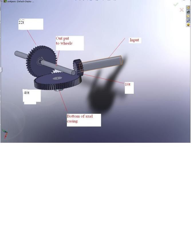
A 22t crown gear like you're using will have a larger OD than a 22t spur like I proposed, for a given pitch. And your pumpkin is still going to be hella wide. Also, your counter gear can be much smaller. It's just an idler so its ratio is unimportant. Last edited by microgoat; 06-14-2009 at 02:23 PM. |
|
| |
|
06-14-2009, 02:51 PM
| #18 | |
| Newbie Join Date: Aug 2007 Location: Santa Cruz
Posts: 36
| Quote:
Last edited by RCCalifornia; 06-14-2009 at 03:04 PM. | |
|
| |
|
06-14-2009, 04:20 PM
| #19 |
| Newbie Join Date: Aug 2007 Location: Santa Cruz
Posts: 36
|
Well ive been thinking and Ive come up with a hopefully easy/ cheap way to make an axle that it is a modification of micro goats idea. Im going to start drawing it up as best as a I can in CAD tonight. Btw anyone know of an easy way to make ring gears in solid works?
|
|
| |
|
06-14-2009, 05:18 PM
| #20 | |
| I wanna be Dave Join Date: Feb 2005 Location: Cleveland, OH
Posts: 8,009
| Quote:
Last edited by microgoat; 06-14-2009 at 05:21 PM. | |
|
| |
|
| |


 Linear Mode


