| |
| |||||||
 |
| | LinkBack | Thread Tools | Display Modes |
 05-09-2010, 07:22 PM
| #1 |
| RCC Addict Join Date: Oct 2009 Location: In the mancave...
Posts: 1,038
|
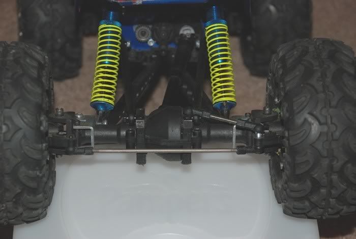
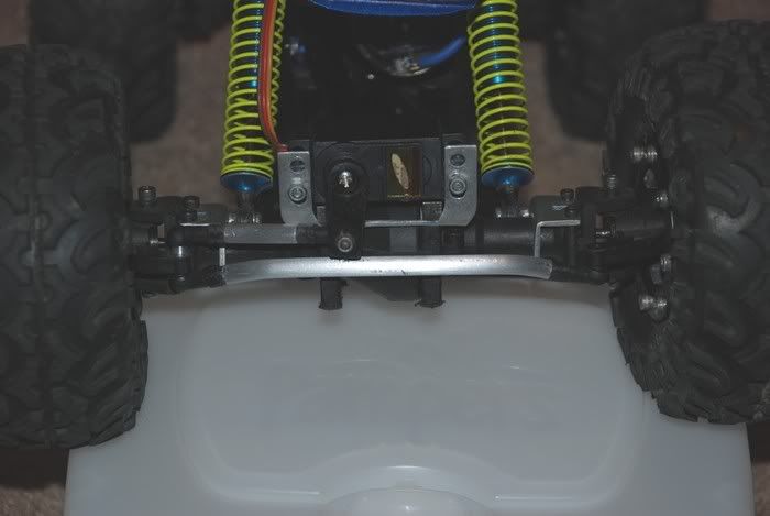
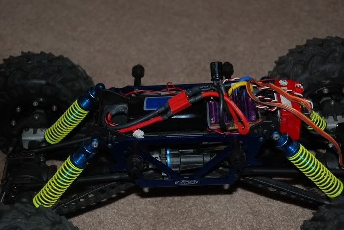
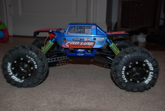
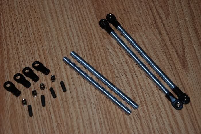
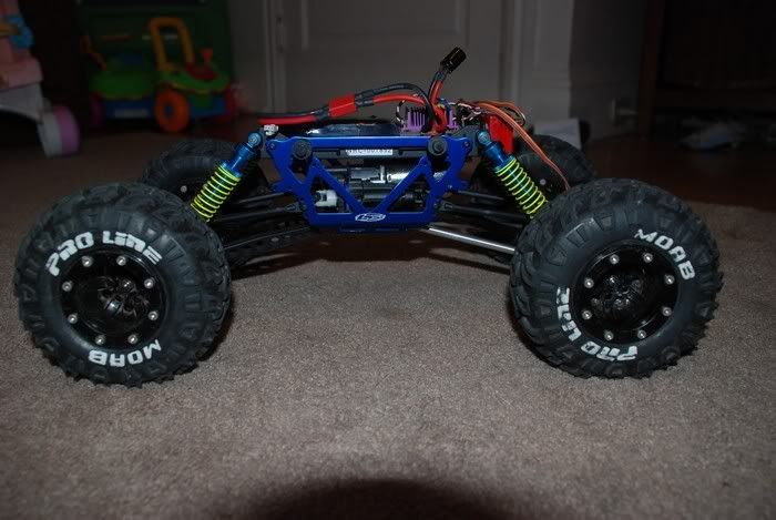
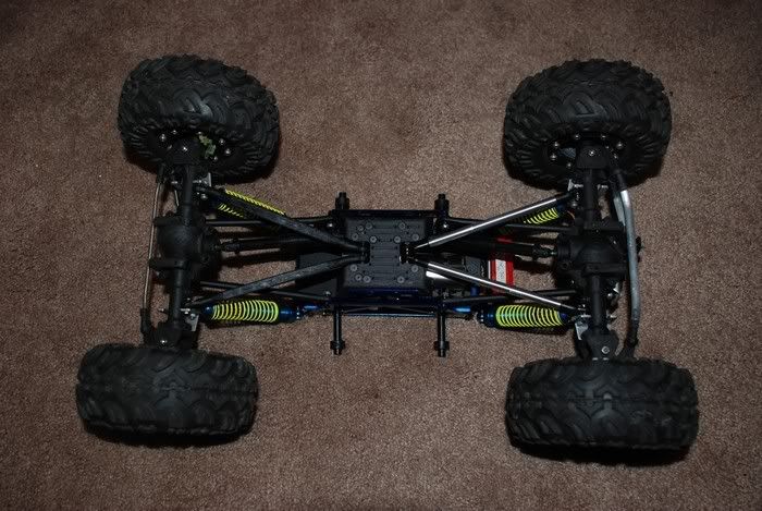
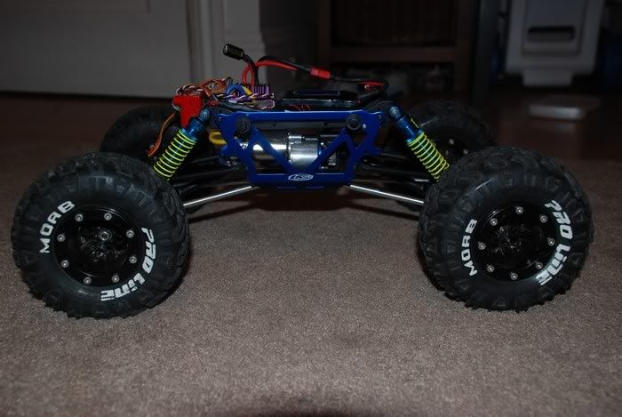
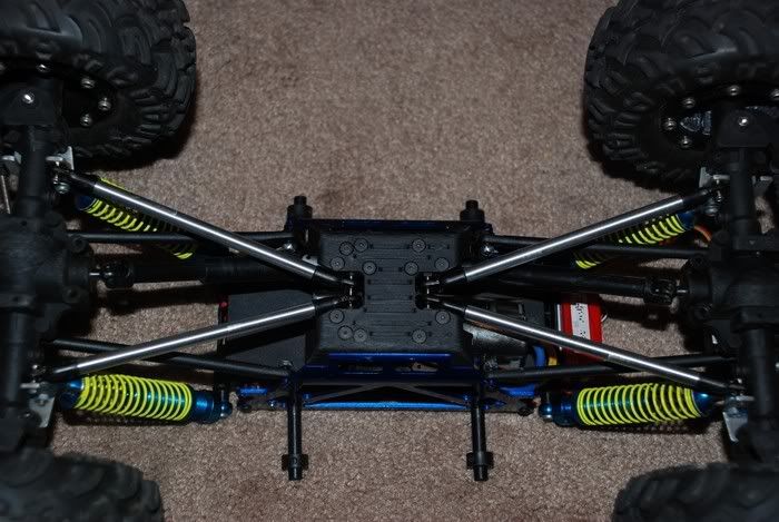
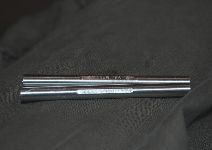
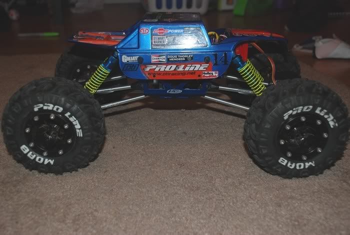
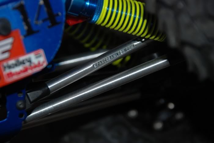
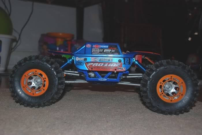
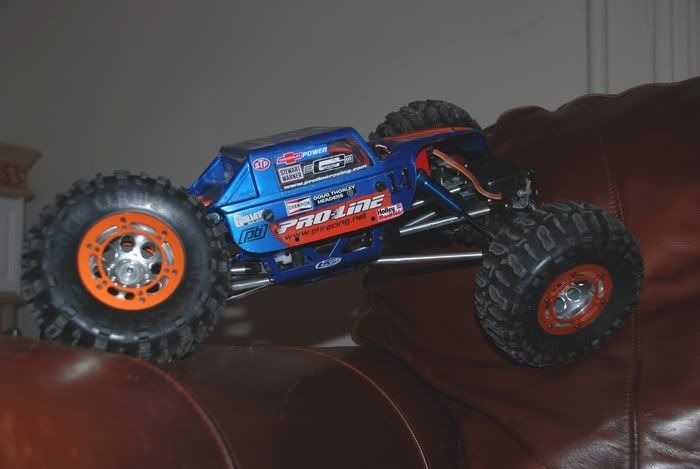
i posted this a couple of days ago on http://www.eparccrawlers.com. i figured i would post here as someone may get a kick out of it. cheers! here's the original post: so i left the first comp thinking..."uff the pti, i need to build a more comp worthy crawler". Losiredcatcrawler pointed out that the pti and the NC pretty much have the same setup as far as links and drive shafts go. on wednesday i bought a NC chassis/tranny/link setup from Tin Soldier, and got to work right away. here's what i've done so far. This is what the PTI looked like before doing anything, as you can see the the motor is way up there. not the hot setup. so the CG is way too high. also everything on it is aluminum. again raising the CG. 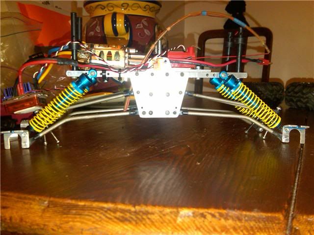 first thing i did was rip the front axle off the PTI and mounted it on the NC links, giving me this... 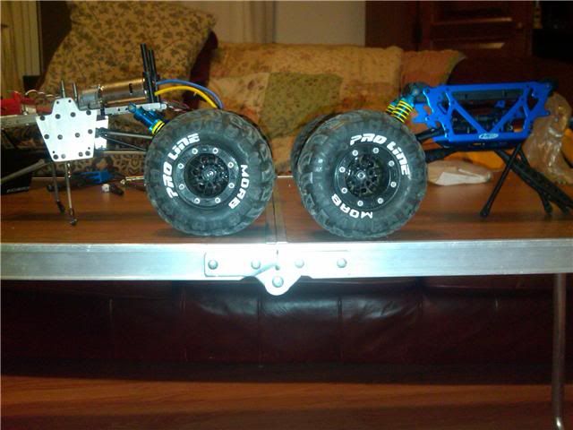 now i knew that the PTI axles would work, i now needed drive shafts. I decided to go with stampede drive shafts. (my poor stampede is in pieces) i took the drive shafts apart and they slipped right onto the output from the tranny. i used two set screw on each yoke to hold them on. i got away from needing new axle input shafts because of the design of the pti input shafts. (no yoke needed there) they are pretty much a direct fit for the stampede shafts. (OGmicromonster from rccrawler.com) below is a pic of the lower links mounted and the drive shafts going to the axle. 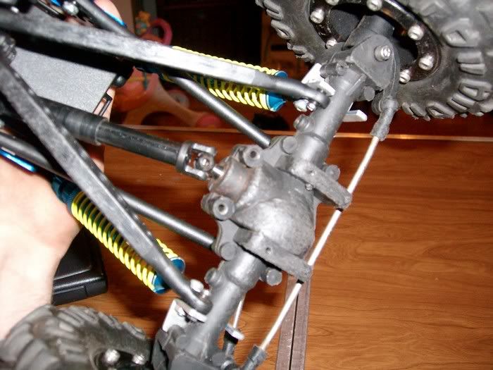 the biggest problem i faced so far was the mounting of the upper links. there was no where to mount them. so today i machined upper link mounts out of steel. i made 6 of them. (only need four, but ya just never know) these are the 2 extra i have. the one on the right shows how the mounts are secured to the axle. the one on the left is a side view showing how the link mounts to it. i used m3x.5 screws to hold it all together. 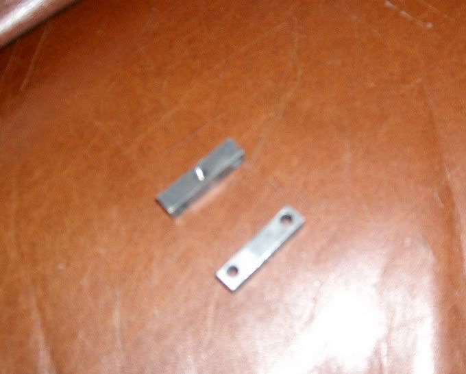 here is what the upper links look like mounted to the axle. it appears that the links will hit the mounts but they do not. (boat load of trigonometry figuring that one out.) you can see where the rear steering is "locked out" on the right. also, when i got done machining the mounts i plated them with black oxide so they wont rust. that is why they are, well, black. 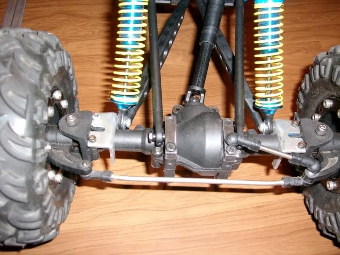 so now all the axles are mounted and are very solid. the drive shafts are on. though, i DO need steel yokes. i just used what i had to make sure every thing works before dishing out $. shocks are mounted. i think i need slightly shorter shocks, but i cant be sure till i have it out for a few test runs. everything moves very smoothly. here is how she is sitting now. the electronics were hooked up about 15 minutes ago. it runs damn good. i think it looks a hell of a lot better too. and the CG is about 2 inches lower. 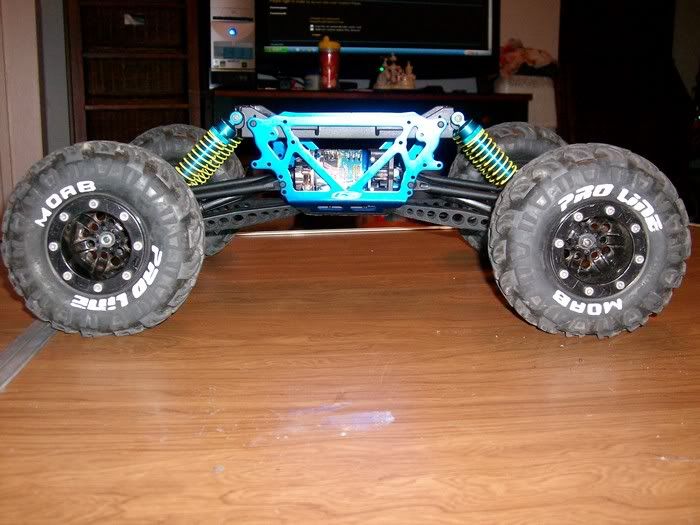 on monday i am gonna spin new lower links. i am not too fond of the delrin ones. also, new lower links will give me that tiny bit of clearance i need for the stampede drive shafts. all in all it runs 10x better than the pti. i am very happy with it. all of this is being done so i can get DIG. though, i gotta get an LCC tranny first. i also plan on getting new axles. this will be a work in progress, so i'll post as i mod. i'd just like to thank Losiredcatcrawler for taking the time at the first comp to look at the PTi and point me in the right direction, and Tin Soldier for selling me the Chassis/Tranny/Link setup. Very Much Appreciated. Last edited by rik; 05-09-2010 at 08:01 PM. Reason: citing credit |

|  |
| Sponsored Links | |
| | |
|
05-11-2010, 07:40 PM
| #2 | |
| RCC Addict Join Date: Oct 2009 Location: In the mancave...
Posts: 1,038
|
i just posted this at eparccrawlers.com, and just wanted to post here as well... Quote:
| |
|
| |
|
05-13-2010, 12:05 PM
| #3 |
| 20K Club   Join Date: Jul 2004 Location: Sending illegals home one Hayabusa at a time.
Posts: 22,981
|
Did I miss reading where you are going to take care of the DRASTIC gearing differences?
|
|
| |
|
05-13-2010, 06:17 PM
| #4 |
| I wanna be Dave Join Date: Oct 2007 Location: Houston
Posts: 3,761
|
I was wondering how your going to get dig with the LCC trans. The trans only provides freewheel. But as it sits now it looks like a fun sportsman.  |
|
| |
|
05-13-2010, 06:40 PM
| #5 | |
| 20K Club Join Date: Jul 2004 Location: Sending illegals home one Hayabusa at a time.
Posts: 22,981
| Quote:
| |
|
| |
|
05-13-2010, 07:32 PM
| #6 | |
| RCC Addict Join Date: Oct 2009 Location: In the mancave...
Posts: 1,038
|
i hear ya guys.. as far as the gearing. i slapped my hpi gru in and it took care of that issue. she has a ton of torque. and as far as the dig goes, i will be using the RC4WD dig tranny with the sealed disconnect. it will JUST fit in the losi chassis. though i will have to machine a new tranny mount/skid plate to accept this tranny. this will give me the three position tranny i desire. engaged, free-wheel, and dig. and if still needed, i will put an RC4WD GRU in it as it is way smaller in size. thanks for taking a look and giving input. here's another update... Quote:
Last edited by rik; 05-13-2010 at 07:37 PM. | |
|
| |
|
05-14-2010, 04:45 PM
| #7 | |
| RCC Addict Join Date: Oct 2009 Location: In the mancave...
Posts: 1,038
| Quote:
| |
|
| |
|
12-22-2010, 08:13 PM
| #8 | |
| RCC Addict Join Date: Oct 2009 Location: In the mancave...
Posts: 1,038
|
this is some more work i did at the end of may. figured i'd post it. as others have mentioned, the pti forum isn't doing too well. this is the post on eparccrawlers.com Quote:
| |
|
| |
|
12-23-2010, 07:22 PM
| #9 |
| Rock Stacker Join Date: Apr 2008 Location: middle of
Posts: 53
|
Serious looking crawler there. So that stampede shaft to PTI input has held up without any issue? Well done |
|
| |
|
12-24-2010, 08:14 AM
| #10 |
| RCC Addict Join Date: Oct 2009 Location: In the mancave...
Posts: 1,038
|
Thanks man. Yea, haven't had an issue yet. Its been in some pretty good binds. actually I've had an issue with the traxxas steel yokes I installed on the tranny. Darn pin came out of the yoke and drive shaft came off. Stampede shafts on steel stampede yokes. I was surprised that's where the failure occurred.
|
|
| |
|
01-12-2011, 10:51 AM
| #11 |
| Rock Crawler Join Date: Nov 2010 Location: roanoke
Posts: 865
|
Awsome!
|
|
| |
|
01-12-2011, 03:24 PM
| #12 | |
| RCC Addict Join Date: Oct 2009 Location: In the mancave...
Posts: 1,038
| Quote:
| |
|
| |
|
01-20-2011, 04:42 PM
| #13 |
| RCC Addict Join Date: Oct 2009 Location: In the mancave...
Posts: 1,038
|
These are 2 post from eparccrawlers.com #1 so the post man brought me a rc4wd dig tranny today. 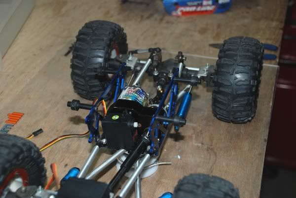 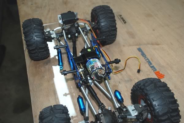 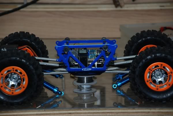 #2 well, last night i said screw it and made the mounting plate. i used a piece of white delrin. will make the final version out of black delrin or aluminum. here's the basic plate attached to the stock skid... 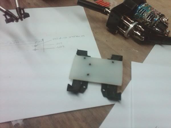 and mounted to the tranny.. 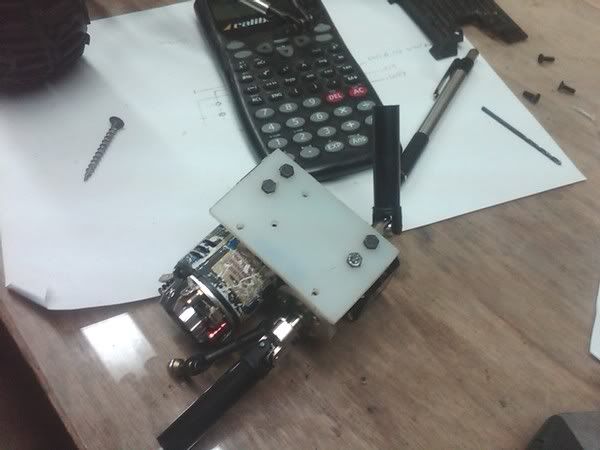 all trimmed up.... 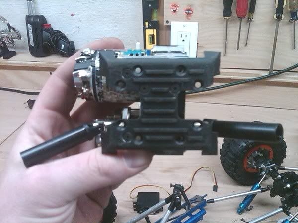 and finally mounted... 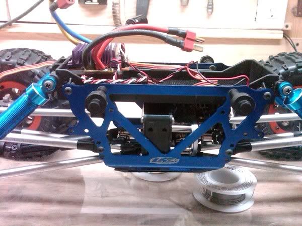 this took me about 1 1/2 hrs from drawing the print to the last pic. i still have to get the servo mount. then make a new rx/esc/lipo plate. if ya notice the front of the skid is "hanging" down a little. i have to shorten 2 of the 4 screws that attach the stock skid the the chassis plates. then she'll be flush... i test ran this after bolted up and wow. its great. i like the locked rear for obvious reasons. but, the free wheel on the rear,...thats where it's at..pulls her up and over some pretty steep verts..though i had to enable the dig by hand. still gotta get the servo mount... |
|
| |
|
02-05-2011, 06:58 PM
| #14 |
| RCC Addict Join Date: Oct 2009 Location: In the mancave...
Posts: 1,038
|
i looked around at servo mounts for the RC4WD dig tranny and found that RC4WD wants $26 shipped for it and CKRC wants $21 shipped for it. So i figured i'd make my own. made it out of 3/16" 6063 aluminum angle i had laying around. First i drilled the mounting holes and trimmed up the one side to contour to the tranny.. 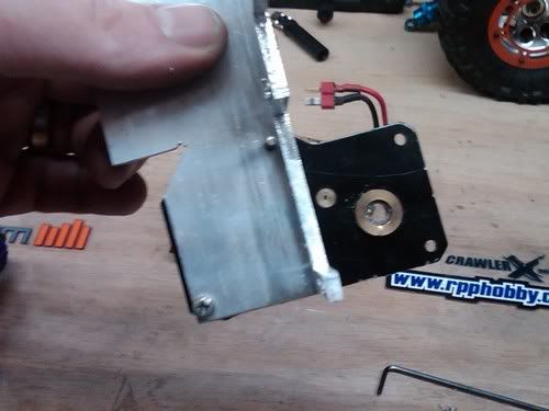 next i cut out the part that holds the servo and drilled the 4 holes to attach the servo to the mount.. 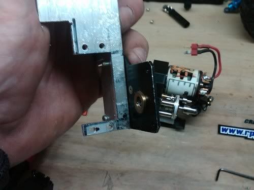 test fit to make sure everything line up before cutting the mount off the 8'' piece of angle. 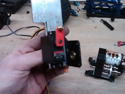 now to hack it off 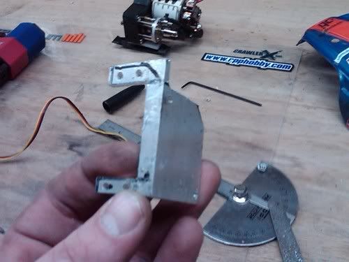 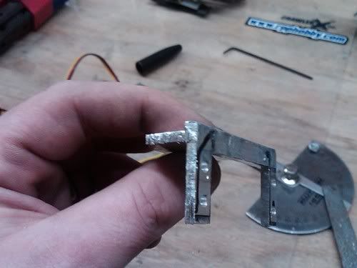 a little polishing and another test fit 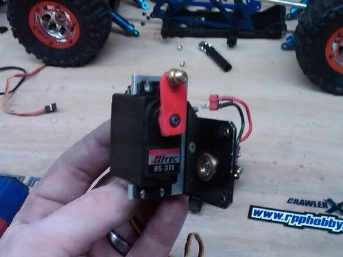 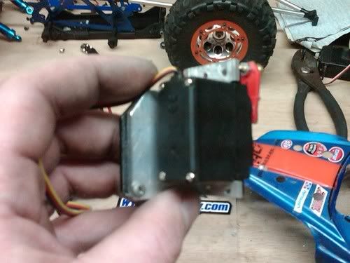 put it all together 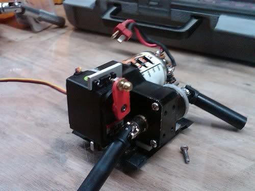 and throw it in. this was the tricky part. i still have to make a new battery tray to mount the lipo, esc, and rx on. but thats another battle for another day. also, i am going to make a nice aluminum link to go from the servo to the disconnect. i used an old link from my clod just to see if it works........and it does. quite nicely too.. i really like the free-wheel. and, i'm diggin' the dig 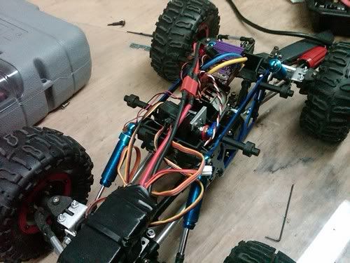 Last edited by rik; 02-05-2011 at 07:01 PM. |
|
| |
|
02-16-2011, 06:13 AM
| #15 |
| I wanna be Dave Join Date: May 2010 Location: Stowe
Posts: 3,987
|
Looks good Rik, so are you going to comp this season??
|
|
| |
|
02-16-2011, 06:11 PM
| #16 | |
| RCC Addict Join Date: Oct 2009 Location: In the mancave...
Posts: 1,038
| Quote:
 answer: yes see ya on the rocks! | |
|
| |
|
02-16-2011, 07:42 PM
| #17 |
| I wanna be Dave Join Date: May 2010 Location: Stowe
Posts: 3,987
|
I like the work you have done to craft this into a comp rig. I have some lightly used rovers if you would like them. Great, bring your hybrid and your "A" game. This is going to be a great season. Last edited by Jslick; 02-16-2011 at 07:44 PM. |
|
| |
|
03-09-2011, 07:00 PM
| #18 |
| RCC Addict Join Date: Oct 2009 Location: In the mancave...
Posts: 1,038
|
Here's another post i posted on EPARCC.... Aluminum Steering Knuckle Upgrade... Well after a lot of contemplating i bit the bullet and tore into the steering on my rig. At the season opener i broke a knuckle on the 2nd gate of the 3rd course. Here's the low down..(note: credit for this mod goes to K_B over on rcc) i ordered a set of TLT aluminum knuckles from ckrc. at first when mock mounted, it appeared that they weren't even close. The ears kept hitting the C's on the axles when turned. So a little filing took care of that. Now they turned. But, there was no way of mounting them as, height wise, they were too short. So i drew up a quick sketch of some bushings for mounting. I drilled, then reamed, the C's to .313". The bushings i turned on the lathe have a .312 diameter hub with a .500" hub. there is a .258'' reamed hole through the bushing, to accept the .257" hub on the knuckle. This bushing keeps the knuckles centered both horizontally and vertically. also, gives it a lot more strength. i made four of them for the front, 2 on each wheel. I also used HPI RS4 dogbones as they are a tad shorter than the stockers. The drive cups had to be ground down. then I threw them on the lathe to drill/ream the hole a little deeper. A band saw and a small file helped me make the two notches deeper... heres a pic of the bushings and knuckles. 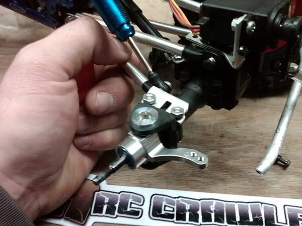 Then i made a new servo mount out of 3/16" aluminum angle. (forgot to take pics) so no more servo flex.... I also spun some new steering links. i bent the connecting link to give some more clearance. man, i love me some new shiny links. 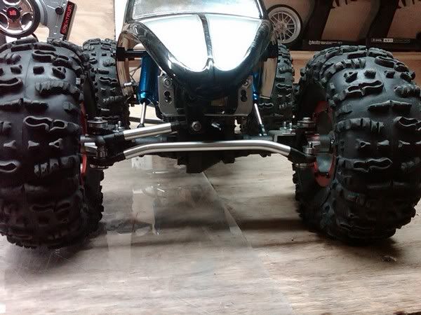 here's a pic of the new knuckles, steering links, and new servo mount. (hard to see the mount) 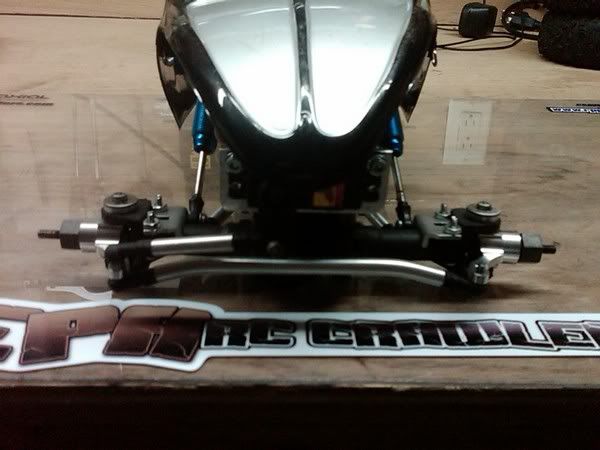 and all put back together. oh, and i glass beaded the orange anodize off the bead rings. (Gonna do the insides tomorrow, then the chassis is next) 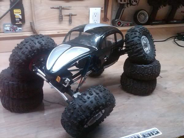 |
|
| |
|
03-10-2011, 08:38 AM
| #19 |
| Newbie Join Date: Feb 2011 Location: Pittston
Posts: 45
|
Great rebuild! The custom links with the CNC'd site links are an awesome touch!
|
|
| |
|
04-01-2011, 06:13 AM
| #20 |
| I wanna be Dave Join Date: May 2010 Location: Stowe
Posts: 3,987
|
Looking great Rik, you have put a lot of work into this. The rovers should do you well. I have other foams if the double duce I gave you are not working well enough. John |
|
| |
|
| |


 Linear Mode


