| |
 01-27-2010, 10:01 PM
| #81 | |
| Quarry Creeper Join Date: Dec 2007 Location: H.B.
Posts: 432
| Quote:
 That's along the lines of what I was thinking. The bend would have been a weak spot. Nick, this thing is going to be a lot of fun to drive!! Nice work!! Just remember to get the same about in the rear for it to work the best.  | |

|  |
| Sponsored Links | |
| | |
|
01-28-2010, 07:08 AM
| #82 |
| RCC Addict Join Date: Aug 2005 Location: Akron
Posts: 1,784
|
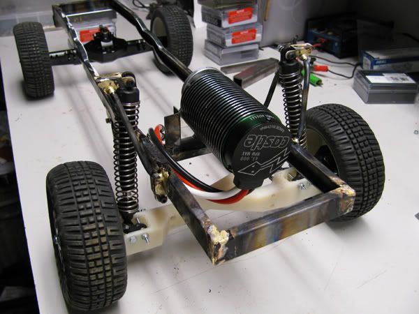
Yeh I'm getting anxious to get this thing running on it's own. I'd really like to get the rear axle mounted up but I'm having a hard time figuring out shock mounts and locations. The prerunner I have been basing this off of runs a leaf sprung rear end and the shocks mount right to the top of the axle where the leaf pack is on the outside of the frame. I'm not going with leafs though. A common setup would be to run the shocks mounted to the middle of the lower link. My issue is that I don't think I can do this because the link would run right under the frame rail and the frame rail would be right in the way of the shock. I need to study on how to get around this....... The thought of cutting the frame rails off behind the cab and doing a full tube rear end on it has been considered but I really really want to keep the full frame out back. |
|
| |
|
01-28-2010, 09:35 AM
| #83 |
| Rock Crawler Join Date: Jan 2007 Location: UK
Posts: 829
|
Really like what you have done with this. I might have to come up with something similar.
|
|
| |
|
01-28-2010, 04:26 PM
| #84 |
| Quarry Creeper Join Date: Jun 2009 Location: SoCal
Posts: 230
|
This is sick Definitely looking forward to updates. The first roll or endo is gonna hurt:-( |
|
| |
|
01-29-2010, 11:18 PM
| #85 |
| Newbie Join Date: Nov 2009 Location: Houma, La
Posts: 14
|
This this is badass. Love that you're using the beams, would have been really cool if you could rig up a ttb setup.
|
|
| |
|
01-30-2010, 02:27 PM
| #86 |
| Rock Crawler  Join Date: Jul 2008 Location: E. City
Posts: 883
|
Are you going to slim up those front beams? They look pretty bulky and I see ground clearance as a possible problem. For the rear suspension, why don't you make mounts for the links and mount them on the outsides of the frame rails, have a ball link on the end like your front beams, then mount the links on the axle but farther towards the wheels as possible, give yourself some triangulation. That would move the link out from under the frame and let you mount the shock to the link up to the cage. Edit: like this:  Or..........you could build this:  Last edited by dont slow down; 02-03-2010 at 12:01 PM. |
|
| |
|
02-03-2010, 11:03 AM
| #87 |
| Pebble Pounder Join Date: May 2008 Location: Va Beach
Posts: 106
|
Subscribed! LOL Great job! Love all the custom stuff!
|
|
| |
|
02-05-2010, 08:10 AM
| #88 |
| Newbie Join Date: Jun 2009 Location: Ryan
Posts: 9
|
Can't wait to see what else you have come up with!! Awesome build and I can't wait to see the finished product! And PLEASE take some video of some jumps so we can see that suspension work! Please! |
|
| |
|
02-06-2010, 07:48 PM
| #89 |
| Newbie Join Date: Aug 2004
Posts: 29
|
Looks awesome, and it's 10,000 times better than what I had planned for my ranger. I bought one of those bodies when I had a ranger, got rid of the ranger and now my rc version has a bed full of dust... Brian |
|
| |
|
02-24-2010, 08:59 AM
| #90 | |
| RCC Addict Join Date: Aug 2005 Location: Akron
Posts: 1,784
| Quote:
As for the rear end setup, I LOVE how that first picture you posted is setup and that is basically what I'll have to do to make the rear end work. It looks like I can flip the axle mounts to make the mounting point a bit wider and I can mount the links off to one side too so I should be able to get the link out away from the frame enough to clear the shocks. I've been insanely busy the last month or so but it looks like things are slowing up. I'm really close to getting the front end together so maybe next week I'll get a chance to button up the steering. | |
|
| |
|
02-26-2010, 12:18 PM
| #91 |
| RCC Addict Join Date: Aug 2005 Location: Akron
Posts: 1,784
|
Ok here's a little update. Got a little time today at lunch to waste some dremel cut off wheels. I decided what the heck, I might as well go for the more complicated multi link steering setup. Looks like it would work good because of geometry. Brackets mounted to the frame and steering links made for the knuckles. 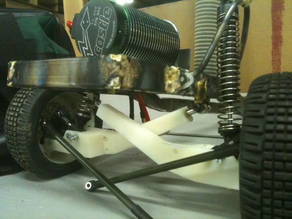 Decided to just go ahead and make the brackets that drop down below the frame. These will allow the steering linking mounting points to be just about the same location as the center line of the beams mounting point. They're not brazed yet just trimmed up and in place. I'll most likely not use the short tubes in the pic, I'll end up brazing on long tubes and trimming them down. I just wanted to see how they might look when finished. 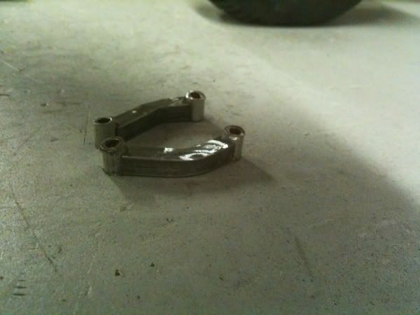 Hopefully I can get them brazed up tonight. Then I'll just have to make a link that connects the left and right brackets together. Then mount the steering servo on the frame and run a link from that to one side of the steering and it should be finished up front. |
|
| |
|
02-26-2010, 03:01 PM
| #92 |
| Rock Crawler Join Date: Dec 2007 Location: buckeye,AZ
Posts: 723
|
cant wait for this truck to get done lol
Last edited by tanner; 03-03-2010 at 03:29 PM. |
|
| |
|
02-27-2010, 12:07 AM
| #93 |
| Newbie Join Date: Jan 2008 Location: newaygo
Posts: 48
|
looks like your steered in the right direction |
|
| |
|
03-01-2010, 11:43 AM
| #94 |
| RCC Addict Join Date: Aug 2005 Location: Akron
Posts: 1,784
|
Alright. Made some good progress today! Still have some bugs to work out but I think this might just work. Both the drop brackets are done and in place. I'm either going to have to reconfigure how the links are mounted or move the chassis mounts. 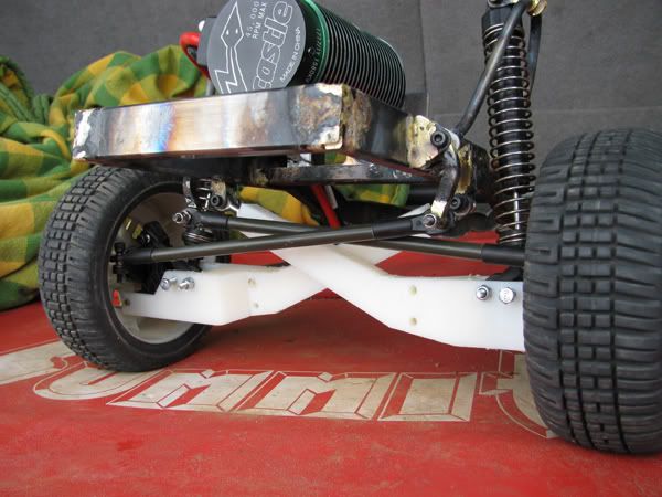 Here's a shot of the steering full lock to one side. I'm going to have to get some thinner head hardware because the clearances are pretty slim. It's REALLY close to being perfect though. I didn't have time to fab a cross link to connect the sides together. I will probably wait until I get the brackets in the right place anyways. I'm pretty sure I can get some rod ands that are a little smaller too. 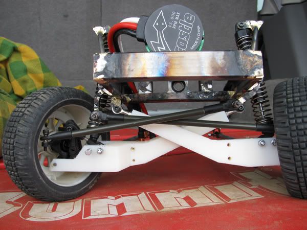 I had to rig this side a little to get the bracket in the right place. Ideally I want the drop bracket in the middle of the chassis bracket so I have to rework this side. 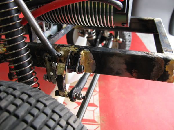 The connection point for the drop bracket and the steering link is just barely below and just barely outside of the beam mount so the steering links follow the beam's travel almost perfectly. 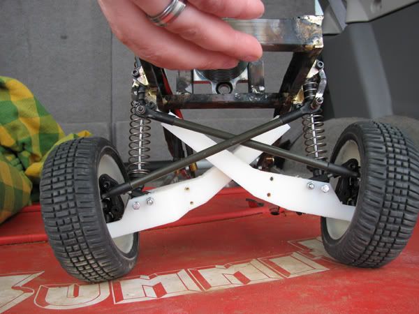 That's it for now! I'll get some better hardware so the fit is better and see where I can move the mounts to make it work smoother. Then I'll make the cross link and mount the servo and give it a test. |
|
| |
|
03-01-2010, 05:23 PM
| #95 |
| Quarry Creeper Join Date: May 2008 Location: Lafayette, Indiana
Posts: 277
|
Glad you're still working on this project I absolutely cannot wait to see this done!
|
|
| |
|
03-02-2010, 11:25 AM
| #96 |
| RCC Addict Join Date: Aug 2005 Location: Akron
Posts: 1,784
|
Nothing too exciting with this update for you guys but to me this was a big headache to conquer! I made some new links and rearranged the mounting points. The idea WILL work for sure but I need to have the drop brackets machined or find something else I can modify. My tolerances just aren't good enough to keep slop out of the steering. Also, the outside tire turns in pretty tight (as much as the knuckle allows) but the inside tire only turns about %60 of what it could turn. Off the top of my head I think it's because my cross link is too long. If I shorten it up it will push this inside tire out more and bring the outside tire in. I just need to find the sweet spot where it moves each knuckle lock to lock. I'll have to mess with the steering links too as this would throw off the toe. At least I know I'm on the right track and it's fine details to make it work well! Ride height with cross link added 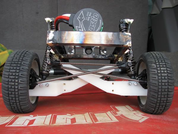 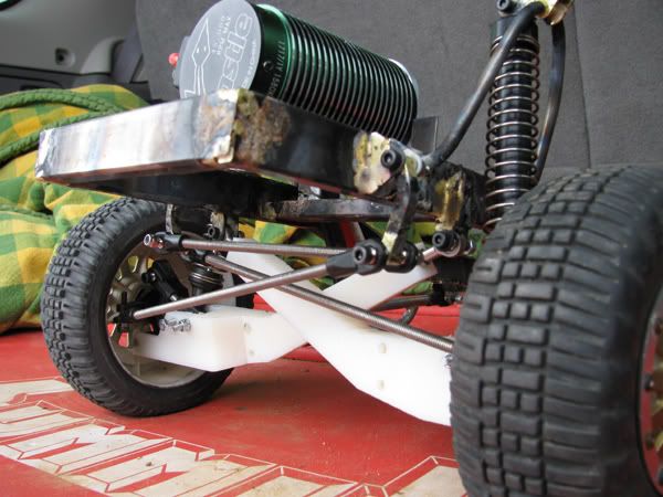 Full bump. You can see on the passenger side there is some slight contact with the other link. I think I can move the chassis mounts up on the chassis a bit to get some more clearance. 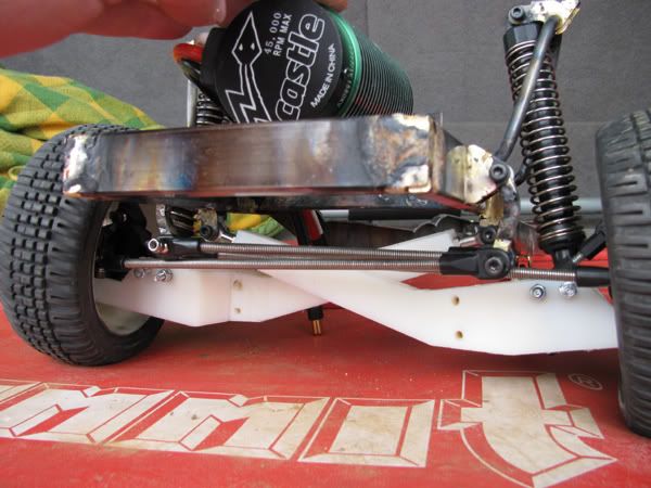 The drop out. Geometry stays aligned perfectly! 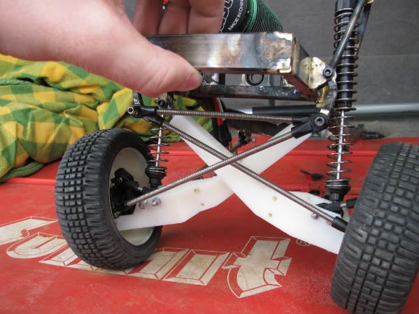 |
|
| |
|
03-02-2010, 07:11 PM
| #97 |
| ~THE SCALE SHOP~ Join Date: Apr 2006 Location: KILLEEN TX
Posts: 10,056
|
finally found the pics of the wheels you were askin about http://img532.imageshack.us/img532/4643/slashlocks2.jpg http://img517.imageshack.us/img517/9933/slashlocks3.jpg http://img237.imageshack.us/img237/1027/slashlocks5.jpg |
|
| |
|
03-02-2010, 07:46 PM
| #98 | |
| Pebble Pounder Join Date: Jul 2009 Location: Calgary, Ab
Posts: 163
| Quote:
| |
|
| |
|
03-02-2010, 08:10 PM
| #99 |
| RCC Addict Join Date: Aug 2005 Location: Akron
Posts: 1,784
|
If I go longer on the cross link that would pull the inside tire back in towards the frame though not push it out more like I need? Remember the links are attached to the opposite side of the frame. I know I'll have more/less bump steer if the cross link is longer or shorter but it should be minimal I'm thinking. |
|
| |
|
03-03-2010, 08:03 AM
| #100 |
| Pebble Pounder Join Date: Jul 2009 Location: Calgary, Ab
Posts: 163
|
I'm using the same style of steering/suspension that you are in my quickie model, but without any particular geometry. I compared the links at straight down, and both longer & shorter cross bars. With the shorter cross bar, the wheels turned away from the frame less than they turned towards the frame. With the longer cross bar (longer tie rods), the turning angle of the wheels away from the frame got a lot greater while slightly reducing the turning angle towards the frame. So said another way: With the shortest link, the inboard wheel steers less than the outboard wheel. As I lengthened the links, the inboard wheel starts to steer more and more and the outboard wheel starts to steer less and less. There are other considerations too, like the position and angle of the steering arms on the hubs. On a system with the steering links in front of the axle, having the outer tie rod ends pushed towards the frame (inboard of the kingpins) you reduce Ackermann (positive Ackermann = more inner wheel steer than outer wheel steer). With BTA steering, it's the opposite. Hope that helps. |
|
| |
 |
| |


 Linear Mode


