| |
| |||||||
 |
| | LinkBack | Thread Tools | Display Modes |
 08-31-2010, 12:54 PM
| #1 |
| Newbie Join Date: Mar 2010 Location: UK
Posts: 30
|
Evenin' all. First post on here - been lurking and admiring for while so I thought I'd share what I have been up to and hopefully pick your brains for some electrikery advice. So, taking a lot of inspiration from supercrawlerfreak's 1:6 Cambell build, I thought I'd jump in the deep end and make my own 4WD, 4WS tube framed buggy. So far I have machined one wheel from 4" billet, one stub axle and knocked up the frame. Most of my time has been spent on making a diff / spool (what a nightmare that was!) for the first axle. It will be electric powered, but I have not the first idea on what type of motor I should use. I want, if possible to be able to crawl and blat about via a two speed gearbox (still to be made!) so what motor / esc / radio setup would you folk recommend? I am in the UK if that influences anything? Anyhow, enough of me talking, here are some pics... Frame - 770mm long 10mm solid bar Axle - 435mm hub to hub. Aaargh - why can I not post attachments...? |

|  |
| Sponsored Links | |
| | |
|
08-31-2010, 01:09 PM
| #2 |
| Quarry Creeper Join Date: Jan 2009 Location: Pacific Northwest
Posts: 295
|
Excellent! Welcome aboard! Im not sure why you cant post pictures, do you have them on a host site like 'photobucket?' |
|
| |
|
08-31-2010, 01:20 PM
| #3 |
| Quarry Creeper Join Date: Nov 2008 Location: London UK
Posts: 273
|
Hurrah! Another fellow UK member. Welcome chappy.  Until we see pics I don't believe you. |
|
| |
|
08-31-2010, 01:23 PM
| #4 | |
| Newbie Join Date: Mar 2010 Location: UK
Posts: 30
| Quote:
It does say that I can't post attachments at the bottom of the page though. Does that mean anything...? | |
|
| |
|
08-31-2010, 02:28 PM
| #5 |
| Rock Crawler Join Date: Mar 2005 Location: Murrieta
Posts: 806
|
Glad I could inspire someone. I cant wait to see what you come up with. lmk if you need any help with part design and what not. As far as a speed control, I'm using the mamba monster since it can handle 6s and run brushed. I personally will be running the new hitec HS-7980TH for steering since its 611in-oz ans just a tad bigger than a standard servo. -Mike Last edited by supercrawlerfreak; 08-31-2010 at 03:36 PM. |
|
| |
|
08-31-2010, 03:03 PM
| #6 |
| Newbie Join Date: Mar 2010 Location: UK
Posts: 30
|
Here we go then. Believe me now...? [URL="]http://www.flickr.com/photos/53579179@N08/4946424834/"] 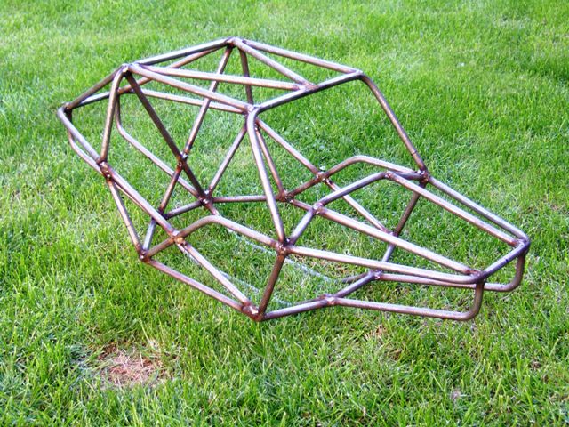 [URL] [URL]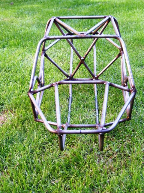 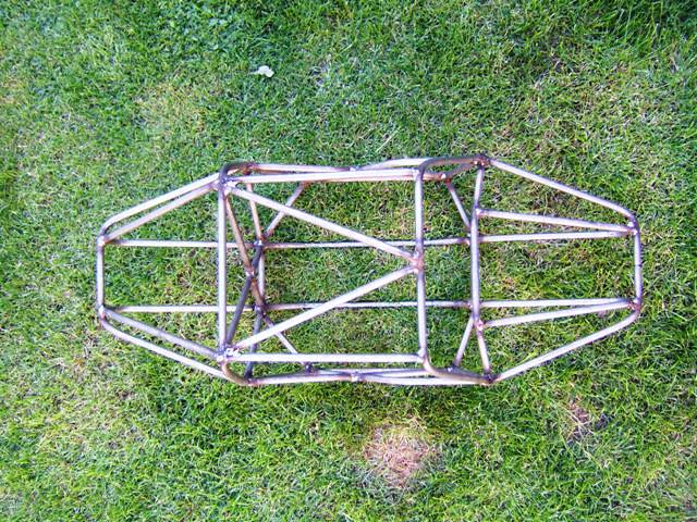  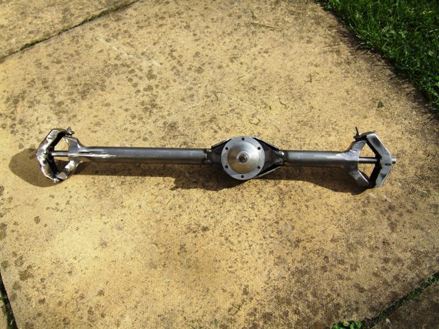 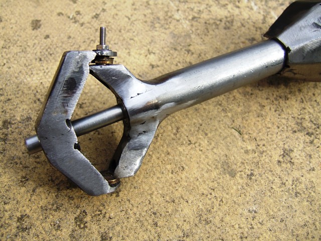 Obviously the axle shaft will be shortened to enable the knuckles to steer, but i needed it like that to ensure the hubs were coaxial. Last edited by THX_138; 03-14-2012 at 04:32 AM. Reason: Fixed image |
|
| |
|
08-31-2010, 03:20 PM
| #7 |
| Rock Crawler Join Date: Mar 2005 Location: Murrieta
Posts: 806
| -Mike |
|
| |
|
08-31-2010, 04:09 PM
| #8 |
| RCC Addict Join Date: Nov 2009 Location: Tulsa
Posts: 1,667
|
Do u have any pics of the build process of ur axels I am getting redy to make my own
|
|
| |
|
09-01-2010, 05:41 AM
| #9 |
| Newbie Join Date: Mar 2010 Location: UK
Posts: 30
|
Copycat? Who me your honour? don't know what you mean!! I'd rather not show pics of the rear of the diff as it isn't pretty. I'll do some step by step pics of the axle build when I do the second axle. I don't have any of this one unfortunately. The frame was mig welded. Last edited by Bishbosh; 09-01-2010 at 11:45 AM. |
|
| |
|
09-02-2010, 08:39 AM
| #10 |
| RCC Addict  Join Date: Sep 2007 Location: Western ND, Bakken central
Posts: 1,653
|
Shit we don't care if it's pretty. Nice axle and chassis |
|
| |
|
09-02-2010, 02:11 PM
| #11 |
| Newbie Join Date: Mar 2010 Location: UK
Posts: 30
|
Forgot to ask - anyone got a source for UJ's? I need a load of them - 8mm shaft but relatively short - only 30mm long. Any clues? the only ones I've found have been £30 each!! |
|
| |
|
09-05-2010, 04:04 PM
| #12 |
| Newbie Join Date: Aug 2009 Location: Riverside
Posts: 44
|
I like the axles |
|
| |
|
09-05-2010, 05:13 PM
| #13 |
| I wanna be Dave Join Date: Jan 2006 Location: ...the burning end of the rope.
Posts: 5,013
| http://www.motionco.co.uk/universal-...ore-p-217.html Google is a wonderful thing,,,took 15 seconds. |
|
| |
|
09-06-2010, 06:19 AM
| #14 | |
| Newbie Join Date: Mar 2010 Location: UK
Posts: 30
| Quote:
I have seen many plastic UJ's and discounted them all on grounds of strength. Do you think the ones you linked to would be strong enough for a model of this size & weight? Serious question, I have my doubts personally as they are only rated to 2Nm....... | |
|
| |
|
09-06-2010, 07:29 PM
| #15 |
| Pebble Pounder Join Date: Jan 2009 Location: Bucktown
Posts: 138
|
vary cool rig the Traxxis 3.3 axle shafts are vary strong but look to big for you tubes http://i695.photobucket.com/albums/v...12-09_2022.jpg BIGGER IS BETTER |
|
| |
|
09-18-2010, 12:14 PM
| #16 |
| Newbie Join Date: Mar 2010 Location: UK
Posts: 30
|
OK, to answer some of your questions - a few pictures: Firstly, the back of the diff (3rd member in your speak ;) )  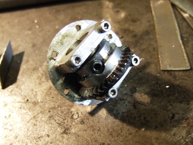 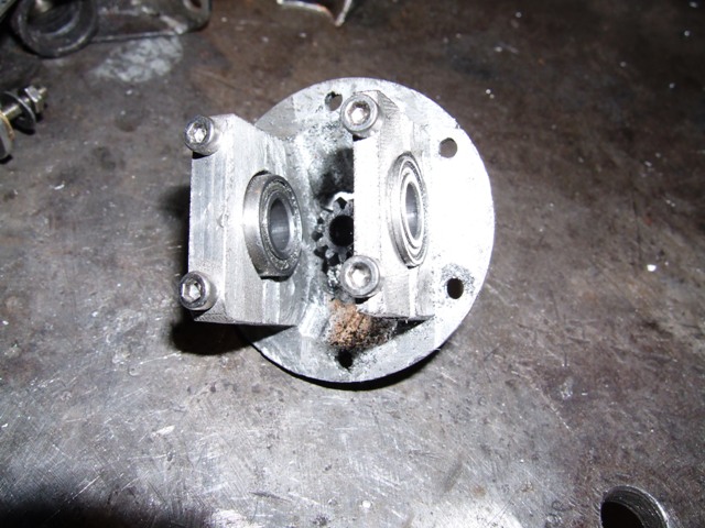 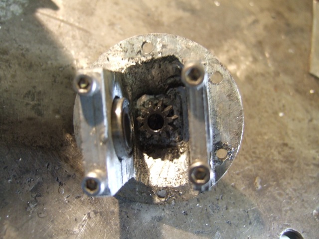 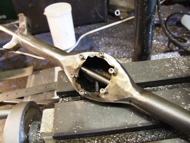 I told you it wasn't pretty!! Next, the first steps of building the axle: Some bits: 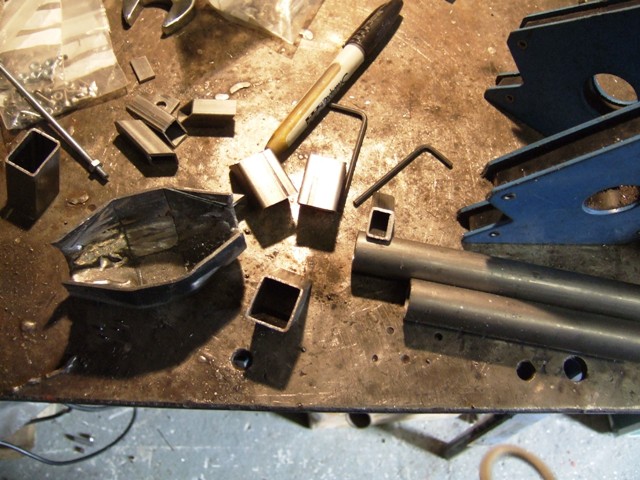 The first thing i did was make the outer half of the steering knuckle. This is simply a short piece of tube that I have machined to receive a pair of bearings: 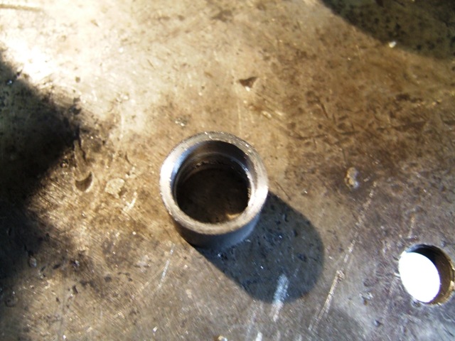 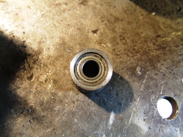 and two bits of box section that I sliced in half. This pic shows me making my third knuckle so I am copying one of the ones I have already made. I made the first one based on a sketch I did of a real spidertrax axle (image on the spidertrax website) 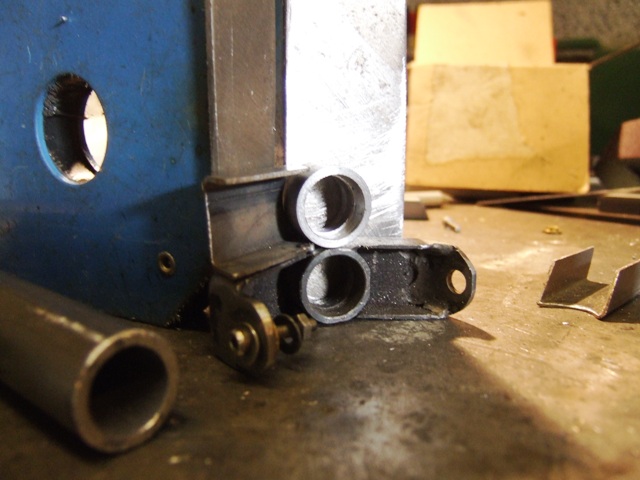 A quick wave of the hot glue gun and you get this:  From here, all you need to do is weld in the top and bottom plates. When I made the first one I used a length of threaded bar to ensure the top and bottom pivot points were coaxial. Once I had the top and bottom plates welded in, I opened up the holes to receive brass bushes: 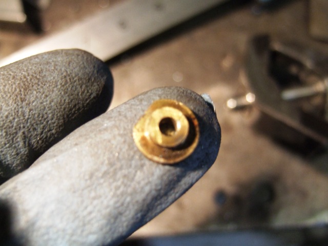 That's as far as I got today - I made a right mess of the second diff so I am currently waiting for some JB weld to cure...... Possibly more tomorrow..... |
|
| |
|
09-19-2010, 02:54 PM
| #17 |
| Newbie Join Date: Mar 2010 Location: UK
Posts: 30
|
Continued with the axle build today: Finished the knuckles by bolting the top and bottom plates to the first axle then welding them to the knuckle, ensuring the drive shaft is engaged in the bearings of the knuckle to keep it all aligned. Doing it this way also ensures the steering axis is aligned and the knuckle will actually swivel! I then moved on to the axle side of the knuckle. Same idea really, this time with complete box section but of a smaller size so it will fit inside the outer arms of the knuckle. Glue them on and you get this: 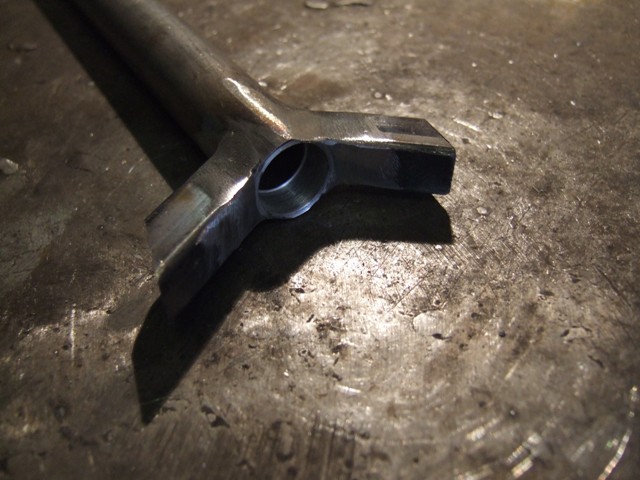 Then it is just a case of putting the top plates on, which I haven't got to yet. The rest of the axle is easy - here are the bits in process..... 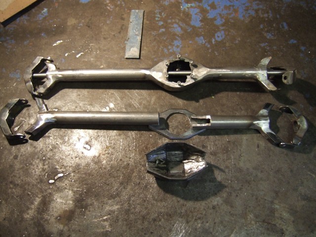 Hopefully this is some use..... |
|
| |
|
09-25-2010, 11:52 AM
| #18 |
| Rock Stacker Join Date: Aug 2010 Location: nanoose bay, bc, canada
Posts: 94
|
those are some pretty sweet steel axles. what did you use for the diff gears?
|
|
| |
|
09-25-2010, 07:30 PM
| #19 |
| cherry bomb   Join Date: Jul 2006 Location: Nanaimo, BC, Canada
Posts: 1,598
|
wow, nice fab work, subscribed for sure, can't wait for more!
|
|
| |
|
09-26-2010, 10:05 AM
| #20 |
| Newbie Join Date: Mar 2010 Location: UK
Posts: 30
|
The diff gears are Protech, I presume from their (now defunct?) 1/6th scale Promax car. Came out of a very dusty odds and sods box at the hobby shop!
|
|
| |
|
| |


 Linear Mode


