| |
| |||||||
 |
| | LinkBack | Thread Tools | Display Modes |
 01-24-2010, 02:08 PM
| #1 |
| I wanna be Dave Join Date: Nov 2005 Location: Here
Posts: 7,317
|
Well, I spent enough time on the OEM chassis, so I decided to make the change. Talking with Don from BWD, he suggested I give this a try. He said with this chassis and a combo of weighting the wheels, I will be unstoppable. So here we go... 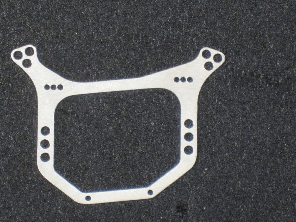 I hope there is enough adjust-ability. It has the same layout as the OEM chassis just opened up more... The conversion will now take place... Last edited by Rckcrwlr; 01-24-2010 at 02:14 PM. |

|  |
| Sponsored Links | |
| | |
|
01-24-2010, 02:09 PM
| #2 |
| I wanna be Dave Join Date: Nov 2005 Location: Here
Posts: 7,317
|
Off subject... I picked up this huge Sharpie yesterday... Look how it makes the chassis look so small...  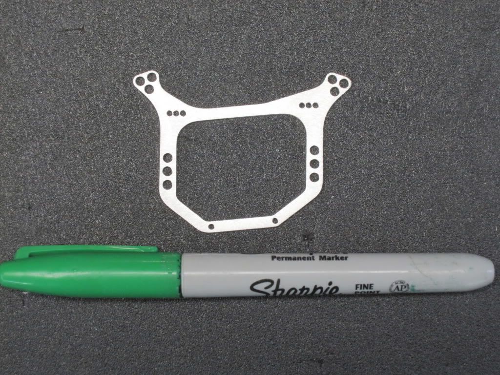 Last edited by Rckcrwlr; 01-24-2010 at 02:15 PM. |
|
| |
|
01-24-2010, 02:10 PM
| #3 |
| I wanna be Dave Join Date: Nov 2005 Location: Here
Posts: 7,317
|
[INDENT] OK back to reality... Introducing the New BWD Micro Wedge Chassis and the BWD Micro Wheel Weight Kit #1 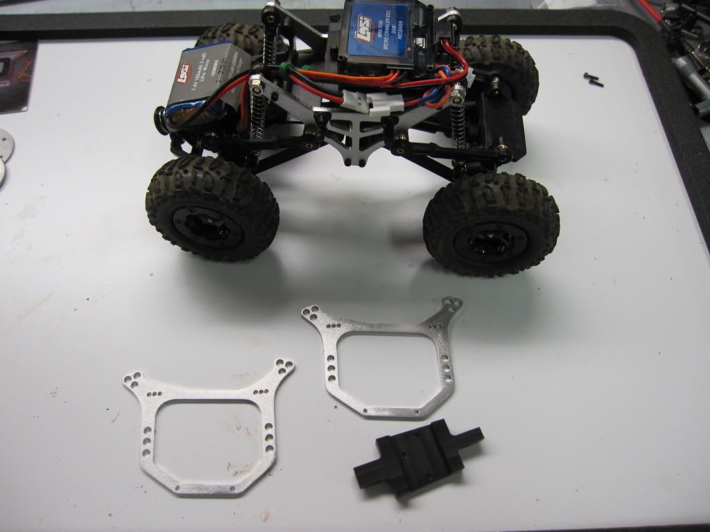 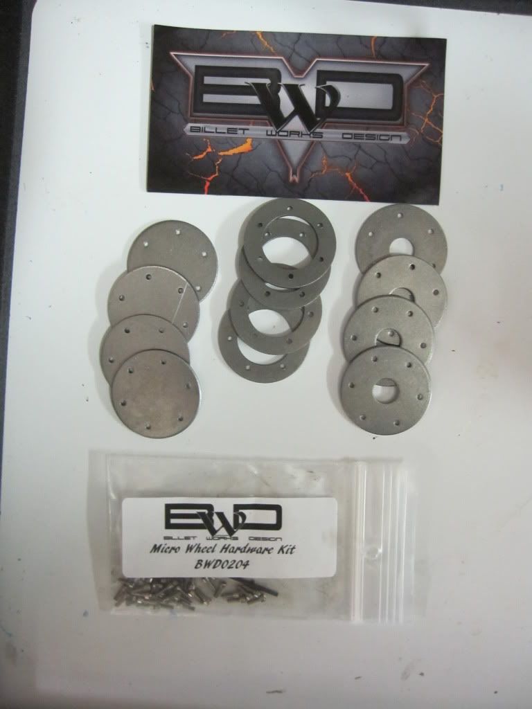 Last edited by Rckcrwlr; 01-24-2010 at 02:16 PM. |
|
| |
|
01-24-2010, 02:10 PM
| #4 |
| I wanna be Dave Join Date: Nov 2005 Location: Here
Posts: 7,317
|
First you need to do is disconnect the servo lead and motor lead from the ESC/Receiver. REmove the 7 cap screws that hold the ESC Mount and Battery Mount in place. 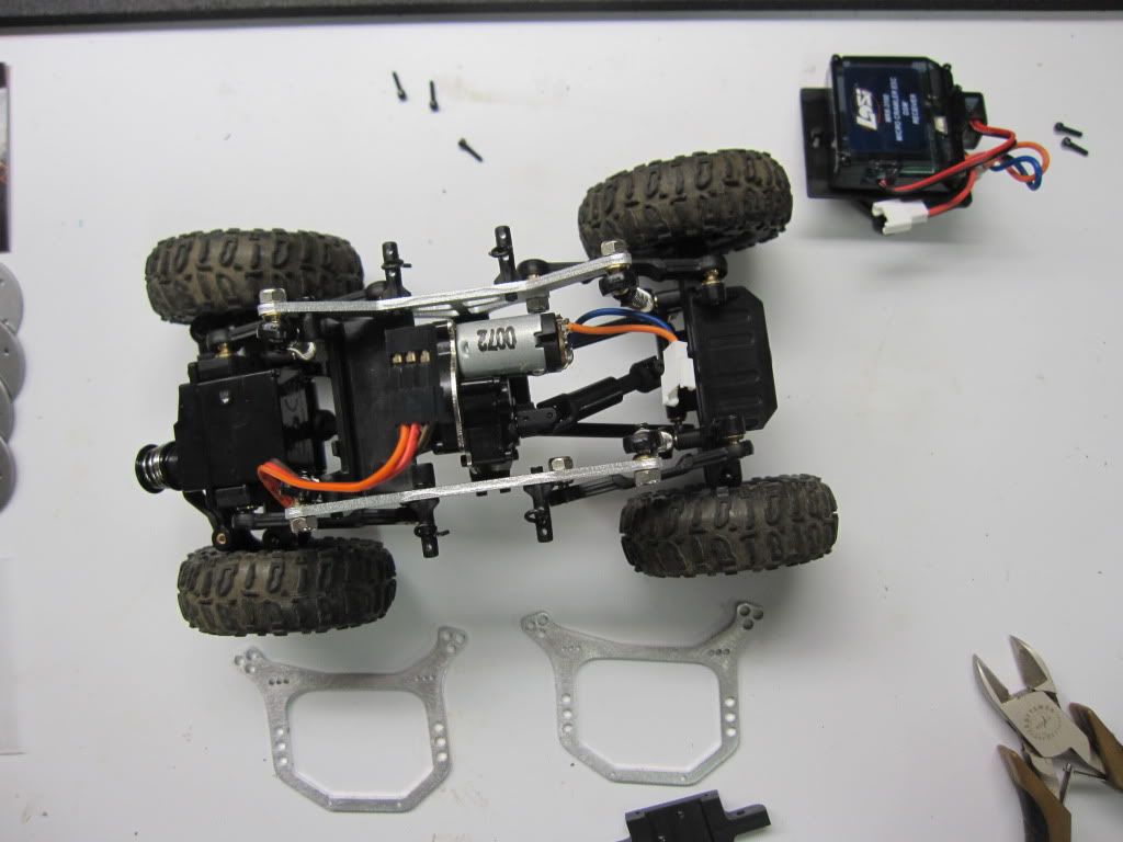 Next, using the Losi Hex Wrench and 4 way to remove the pivot balls with the shocks from the chassis 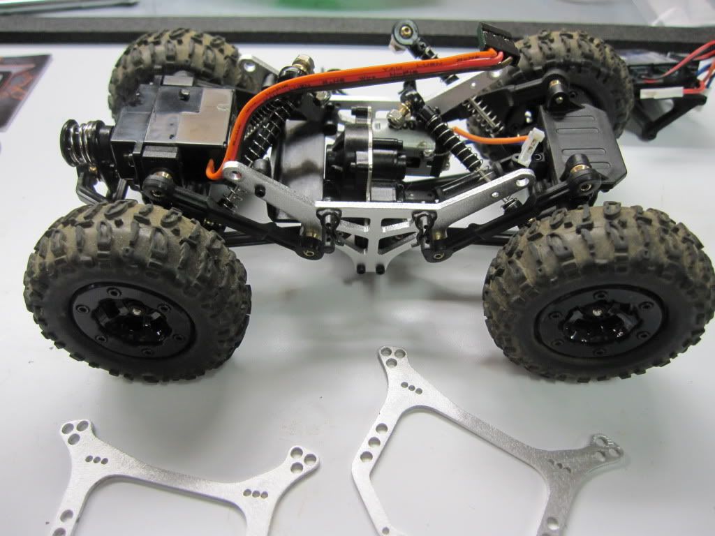 Now, using needle nose pliers, gently twist the lower links off the pivot balls and remove. Put the axles aside for now. 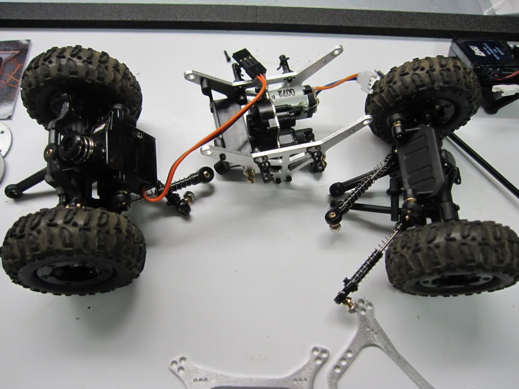 Last edited by Rckcrwlr; 01-24-2010 at 02:17 PM. |
|
| |
|
01-24-2010, 02:13 PM
| #5 |
| I wanna be Dave Join Date: Nov 2005 Location: Here
Posts: 7,317
|
Now separate the chassis plates from the skid/tranny by removing the 4 cap screws. Transfer the body mounts and upper link mount balls to the new plates. Move the rear Pivot Balls Inboard (Note Front of chassis is higher side) 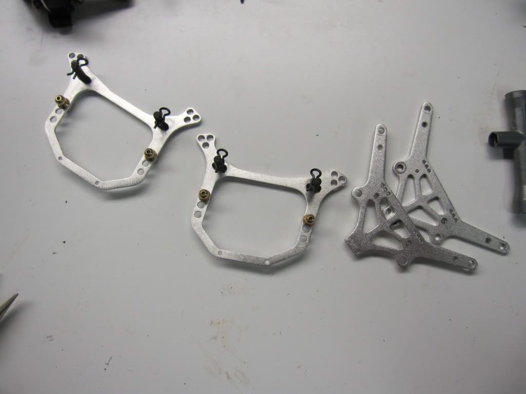 Remove the Pivot balls from the skid plate...you will need to cut the threads for the new skid plate. They are brass so you can use nippers or wire cutters (2 Fronts to 1/8", 2 Rears to 5/16"). Clean up the threads and slowly thread them in the new skid plate (The narrow side is the front) 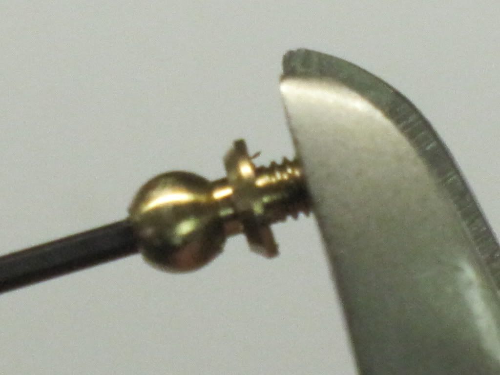 Now you need to assemble the links. The two bend links (all thread) are the lower-rear links. Thread the ends in to make them no larger than 1.5" or you will have issues with the driveshafts separating. 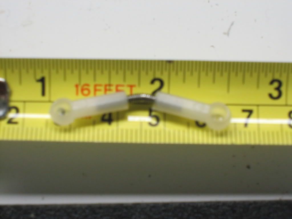 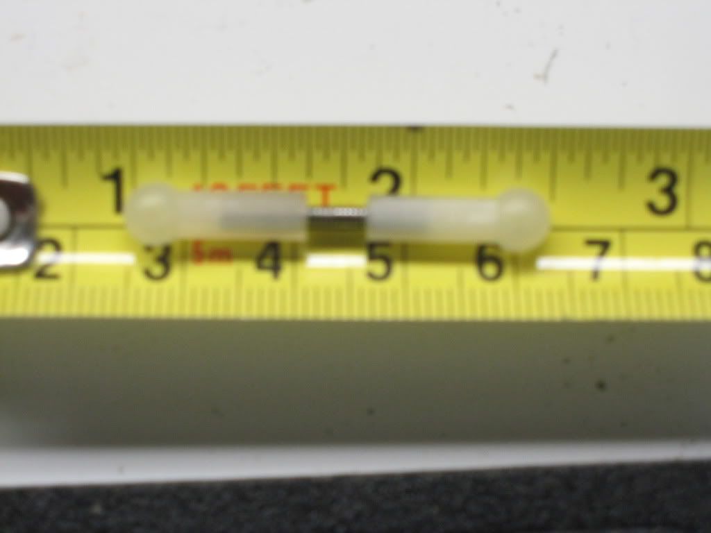 Mount them onto the skid plate...then mount the tranny with the OEM screws. 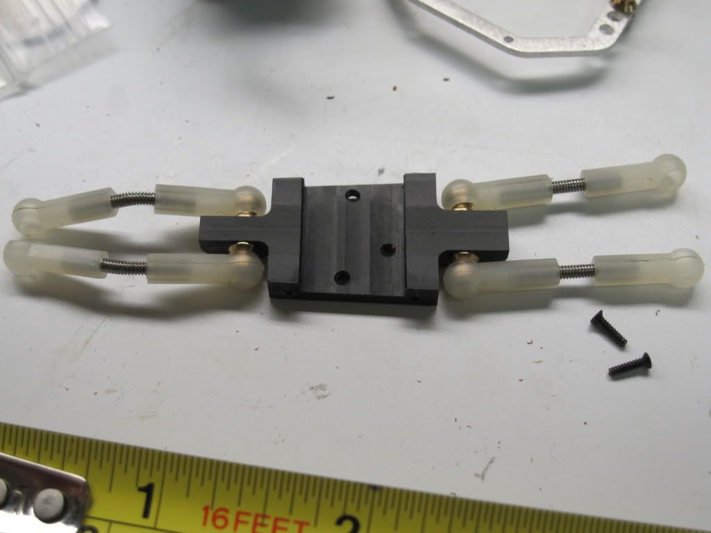 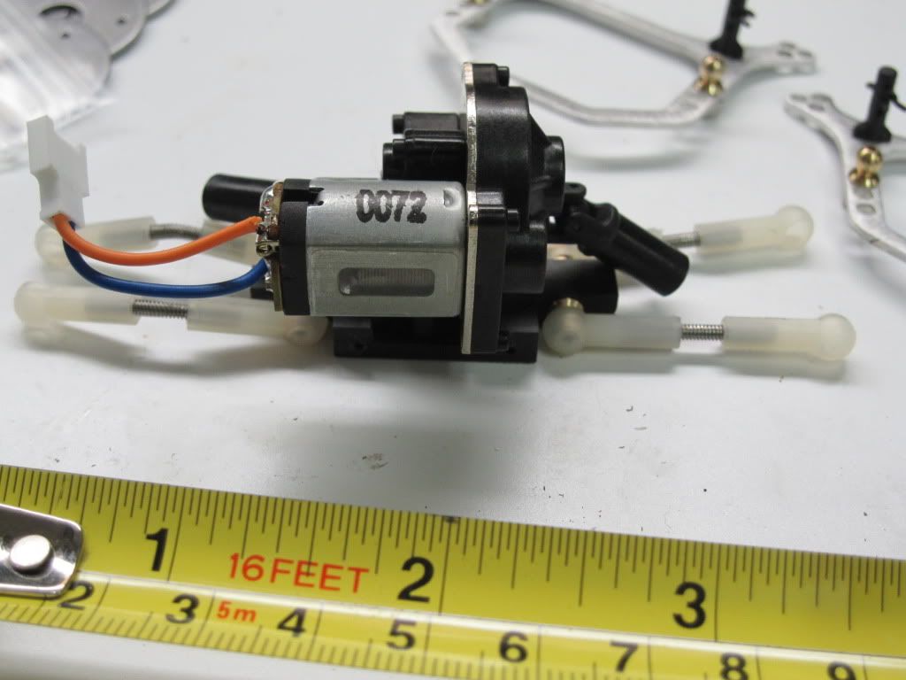 On the rear upper link mount, move the Pivot Balls Inboard... BEFORE 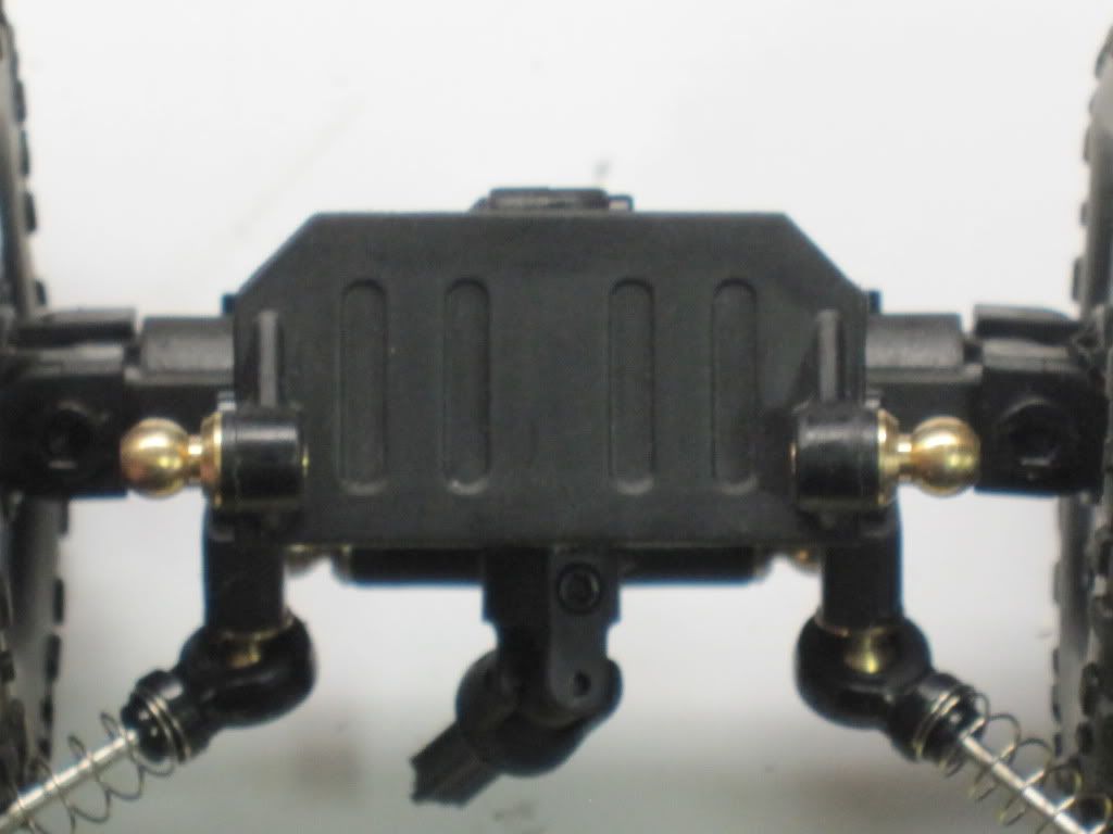 AFTER 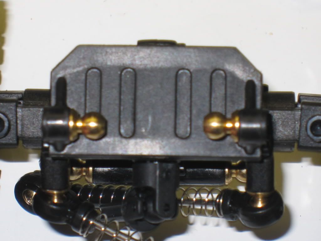 Last edited by Rckcrwlr; 01-24-2010 at 02:20 PM. |
|
| |
|
01-24-2010, 02:22 PM
| #6 |
| I wanna be Dave Join Date: Nov 2005 Location: Here
Posts: 7,317
|
Attach the chassis plates...making sure that you have the higher part of the chassis to the front and the wider part of the skid plate 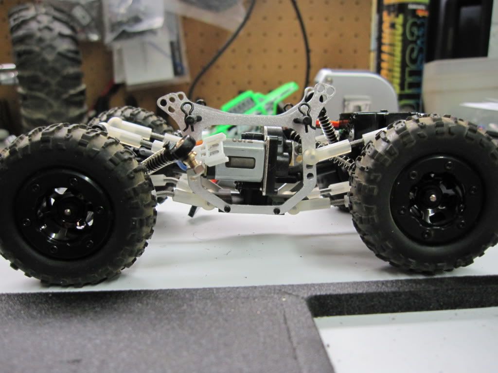 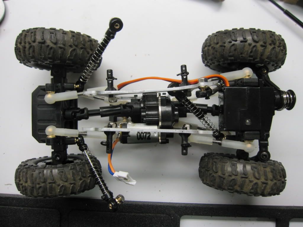 Then mount the shocks... (Make sure your rear shocks are mounted inboard on the chassis) 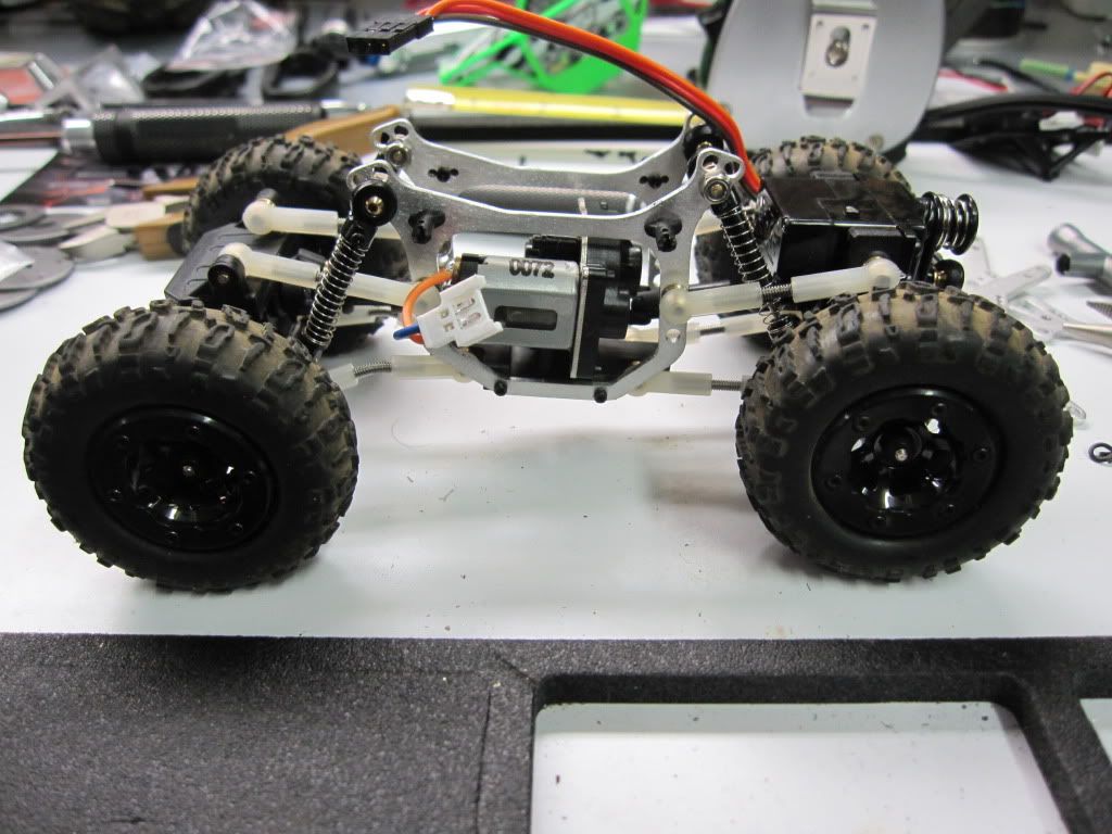 |
|
| |
|
01-24-2010, 02:24 PM
| #7 |
| I wanna be Dave Join Date: Nov 2005 Location: Here
Posts: 7,317
|
With the limited space, I decided to remove the case from the ESC/Receiver. 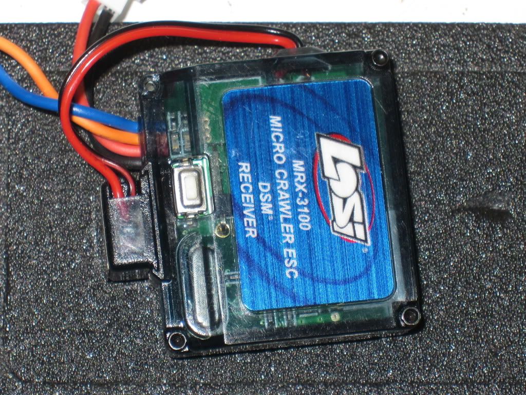 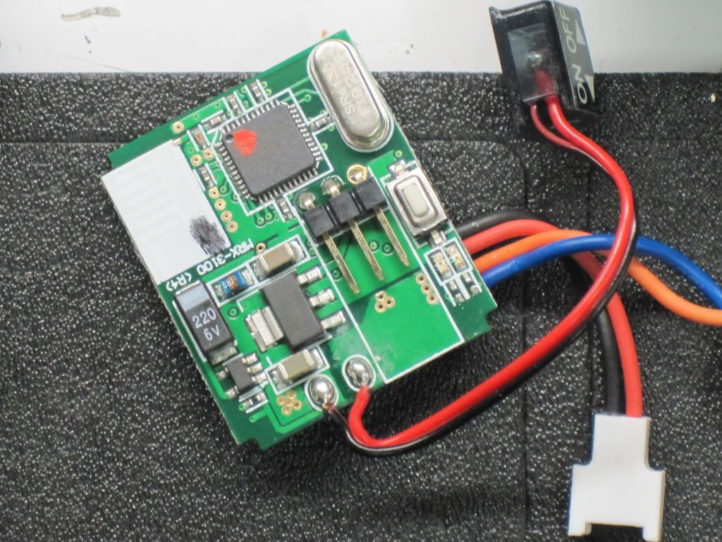 I used battery shrink to keep it from shorting. 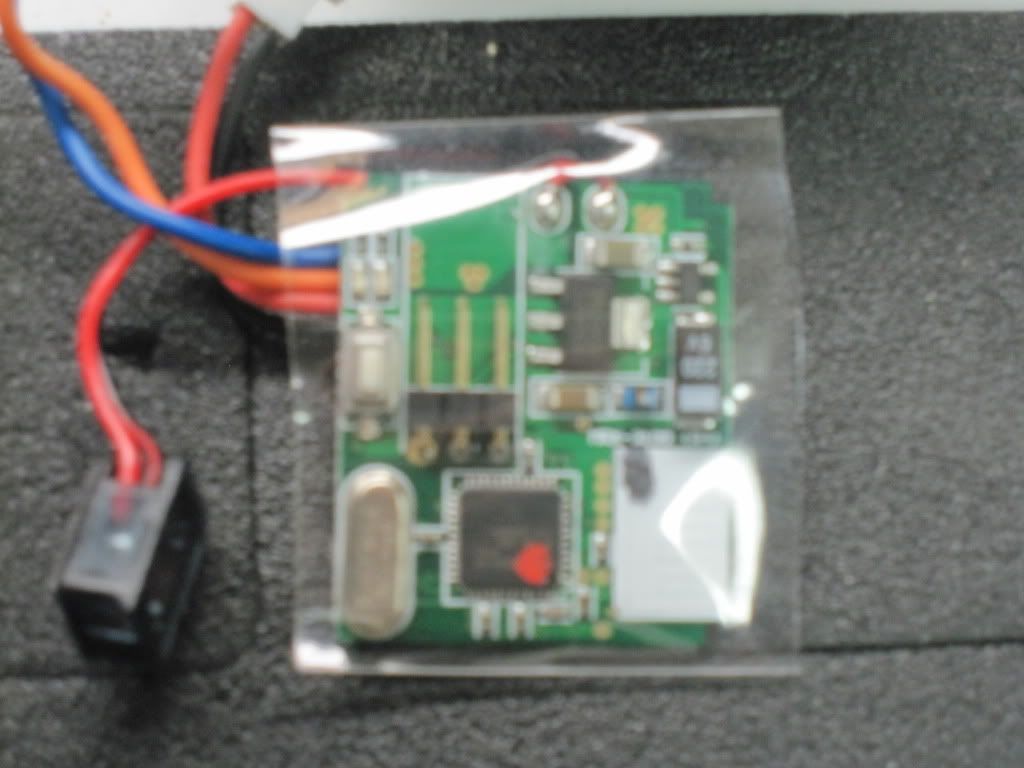 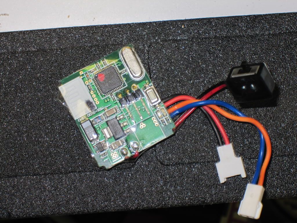 I then cut access for the servo plug and the bind button. It got wire tied to the top of the chassis... 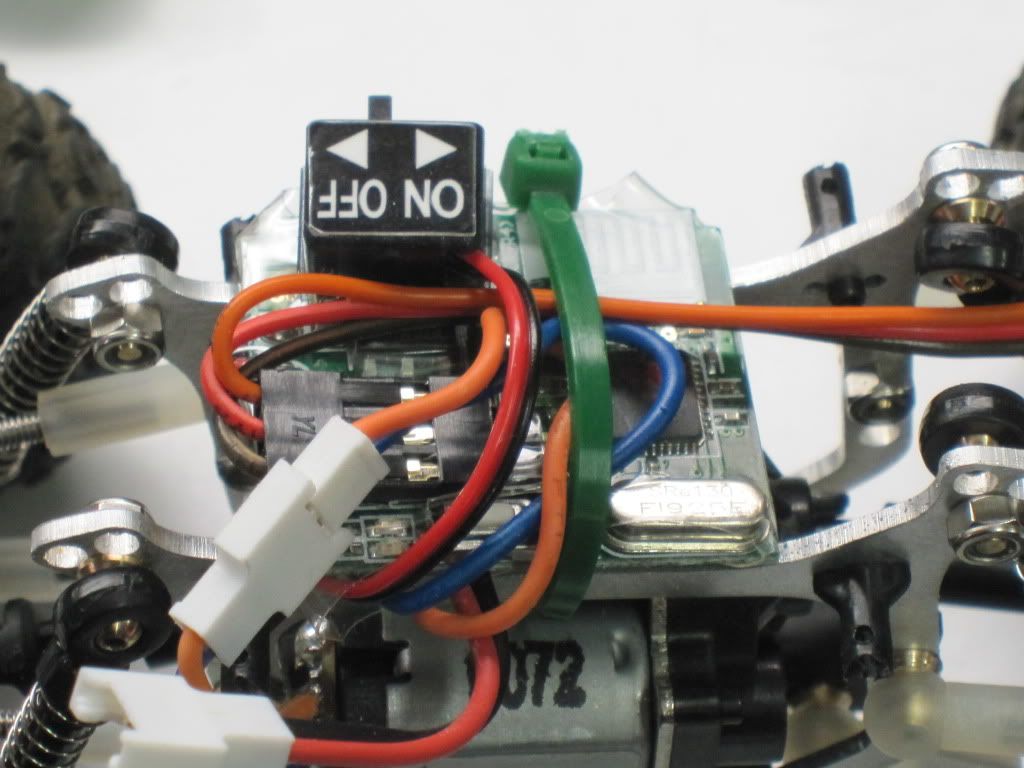 |
|
| |
|
01-24-2010, 02:25 PM
| #8 |
| I wanna be Dave Join Date: Nov 2005 Location: Here
Posts: 7,317
|
Trying to decide where to put the LiPo...Thinking on the opposite side of the motor but possibly on the front servo. Mounting the body is creative. BWD supplies you with 3mm screws and fuel tubing. You put the new holes in the body, place the screws in with the tubing on the inside..then just slide the tubing on the existing body mounts. There we go...Done...Or am I?? 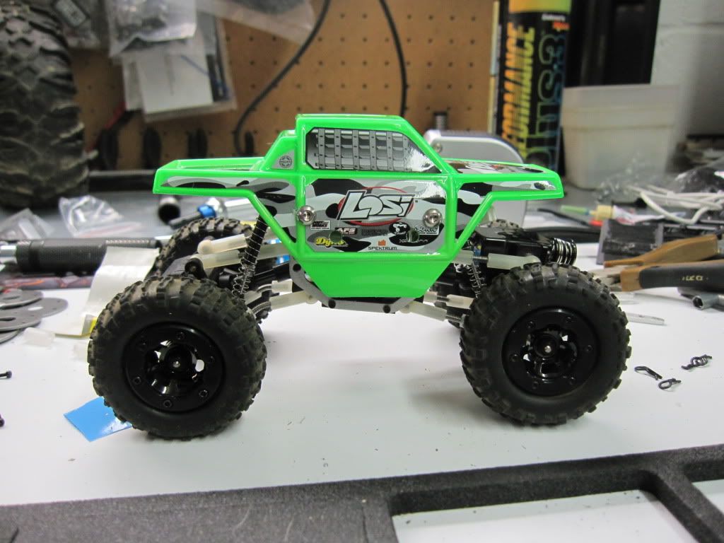 |
|
| |
|
01-24-2010, 03:49 PM
| #9 |
| Adilynsdad too!   Join Date: May 2004 Location: G ville
Posts: 8,844
|
great write up and build... FYI, I chucked a ball stud in my drill and put some lapping compound in the ball end. A few mintutes later after spinning them and no binding in the ends at all |
|
| |
|
01-24-2010, 04:00 PM
| #10 |
| I wanna be Dave Join Date: Oct 2007 Location: Scumrise, Flooriduh
Posts: 5,181
|
Build looks great! I can't wait for mine to arrive.
|
|
| |
|
01-24-2010, 04:05 PM
| #11 |
| I wanna be Dave Join Date: Jun 2007 Location: Earth
Posts: 2,488
|
Nice build. Cycling the suspension will free up the suspension, but BD's way is faster and makes the links move super smooth. Needs Vertex Micro-Locks Don BWD |
|
| |
|
01-24-2010, 04:30 PM
| #12 | |||
| I wanna be Dave Join Date: Nov 2005 Location: Here
Posts: 7,317
| Quote:
Quote:
Quote:
BD, That is what I am going to do.... BWD, I saw the new wheels...they are sweet.. Last edited by Rckcrwlr; 01-24-2010 at 04:33 PM. | |||
|
| |
|
01-24-2010, 04:50 PM
| #13 |
| Rock Stacker Join Date: Jan 2009 Location: Toledo
Posts: 61
|
Any testing to tell if mounting the rear upper links on the outside helps or hurts performance? I know it was suggested to mount them inside the chassis plates but didn't know what you have found.
|
|
| |
|
| |


 Linear Mode


