| |
 02-16-2009, 09:13 PM
| #1 |
| RCC Addict Join Date: Jan 2007 Location: San Jose
Posts: 1,697
|
Here are some pics of my first build here. I welcome feedback and suggestions in any way. Hope this helps anybody out as I have received tons of help. Let the learning begin: slingshot cfx chassis.  delrin links with rc4wd heims.  Last edited by 5150bronco; 02-16-2009 at 09:15 PM. |

|  |
| Sponsored Links | |
| | |
|
02-16-2009, 09:42 PM
| #2 |
| Pebble Pounder Join Date: Oct 2008 Location: Fresno
Posts: 139
|
OK, sweet Chassis, sweet links..... don't tease, where's the rest?
|
|
| |
|
02-16-2009, 09:46 PM
| #3 |
| Rock Crawler Join Date: Nov 2008 Location: lakeside
Posts: 554
|
yeah its a great start stop hidding it.
|
|
| |
|
02-17-2009, 03:38 PM
| #4 |
| RCC Addict Join Date: Jan 2007 Location: San Jose
Posts: 1,697
|
more pics, trying to get use to this iphoto app. mayhem double phatty, wide offset.  panther tires  > I am going to make hybrid foams with memory and stock proline foams for side wall. Here is the link mount I cut to use 4-link and make room for bta steering I am trying to figure out now.  Last edited by 5150bronco; 02-17-2009 at 05:06 PM. |
|
| |
|
02-17-2009, 04:57 PM
| #5 |
| RCC Addict Join Date: Jan 2007 Location: San Jose
Posts: 1,697
|
dig servo hitec 225  the idea is to see where the servo horn and the pick up point for the tie rod...... Not sure if this will be too close for the steering arm....????here are ckrc high steer knucks  welcome all the ideas and comments. Last edited by 5150bronco; 02-17-2009 at 05:07 PM. |
|
| |
|
02-17-2009, 10:19 PM
| #6 |
| Quarry Creeper Join Date: Oct 2008 Location: Southwest VA
Posts: 361
|
Nice start! Cant wait to see it done. I just got finished with a Slingshot SE chassis a few weeks ago. Are you going tomount the dig servo on the electronics tray?
|
|
| |
|
02-17-2009, 11:39 PM
| #7 | |
| RCC Addict Join Date: Jan 2007 Location: San Jose
Posts: 1,697
| Quote:
| |
|
| |
|
02-18-2009, 01:34 AM
| #8 |
| Pebble Pounder Join Date: Nov 2007 Location: Alice Springs/Australia
Posts: 131
|
Not sure if this will be too close for the steering arm....????here are ckrc high steer knucks Hey Mate looks the goods so far the CKRC HI CLEAR knuckles should work cause when i bought my CKRC BTA kit they give you delrin standoffs to space between your knuckle and drag link... |
|
| |
|
02-18-2009, 08:29 AM
| #9 | |
| RCC Addict Join Date: Apr 2008 Location: In The Machine, "Turn the light back ON"
Posts: 1,082
| Quote:
| |
|
| |
|
02-18-2009, 12:54 PM
| #10 | ||
| RCC Addict Join Date: Jan 2007 Location: San Jose
Posts: 1,697
| Quote:
can you post pic of what you are using? Quote:
I love those for sure! Using em on my scaler I am building and will start a thread after this is done. I will definitely need help setting up dig to so........:smile: | ||
|
| |
|
02-18-2009, 03:12 PM
| #11 |
| RCC Addict Join Date: Jan 2007 Location: San Jose
Posts: 1,697
|
Now I am trying to figure how to make or cut a MIP driveline with stock length to fit this chassis and DNA Dig? Any suggestions? |
|
| |
|
02-18-2009, 04:17 PM
| #12 | |
| Ex Nor-CalRCRC slave  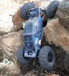 Join Date: Dec 2008 Location: San Mateo, CA.
Posts: 2,242
| Quote:
| |
|
| |
|
02-18-2009, 06:58 PM
| #13 |
| Holmes Hobbies   Join Date: Jan 2007 Location: No Where
Posts: 2,751
|
Be careful and don't cut to much,the splines on the female shaft only go half way down the shaft Anyway,looking good,Your gonna LOVE that chassis  |
|
| |
|
02-18-2009, 08:02 PM
| #14 | |
| Ex Nor-CalRCRC slave Join Date: Dec 2008 Location: San Mateo, CA.
Posts: 2,242
| Quote:
| |
|
| |
|
02-18-2009, 09:54 PM
| #15 | ||
| RCC Addict Join Date: Jan 2007 Location: San Jose
Posts: 1,697
| Quote:
Quote:
The issue my buddy had doing this was: He did not cut female shaft at all and cut male shaft and grinded the part towards u-joint which caused the male shaft to spin freely in female. So would you guys post pic and say lengths of what was cut that works? THanks guys! | ||
|
| |
|
02-18-2009, 10:01 PM
| #16 |
| Holmes Hobbies Join Date: Jan 2007 Location: No Where
Posts: 2,751
|
The male shaft will be fine but the female doesn't have splines all the way to the bottom.Like gunnar said,check it with something you can feel where the splines end and don't cut them all away.MPI also makes a short male shaft for disconnect. |
|
| |
|
02-18-2009, 10:06 PM
| #17 | |
| RCC Addict Join Date: Jan 2007 Location: San Jose
Posts: 1,697
| Quote:
How much to cut off with your experience? Thanks CD! | |
|
| |
|
02-18-2009, 10:07 PM
| #18 |
| Ex Nor-CalRCRC slave Join Date: Dec 2008 Location: San Mateo, CA.
Posts: 2,242
|
The length YOU will have to determine. Really no need to post a pic, it's just the end of the shaft going against a grinder. To me, if the shaft is too long, just take alittle off at first, like 1/8" or so and check the fit, still too long? cut alittle more then. In my case, I couldn't get full suspension cycling, cuz the shaft bottomed out and axle wouldn't move upwards anymore. After cutting about 1/8" or so off each end, I was good to go. Did your friend cut so far as to remove all the splines?
|
|
| |
|
02-18-2009, 10:13 PM
| #19 |
| Ex Nor-CalRCRC slave Join Date: Dec 2008 Location: San Mateo, CA.
Posts: 2,242
|
Here is a pic from my build, you will see what I mean: 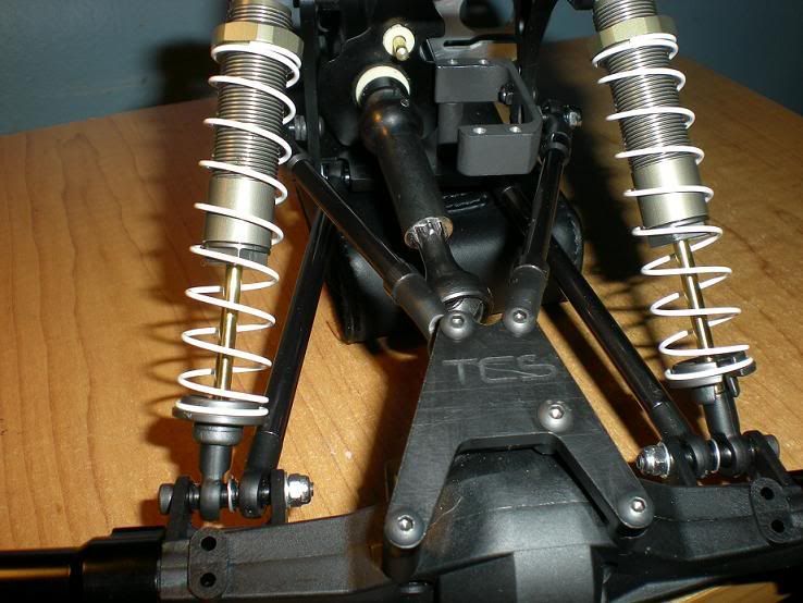 The pic is at full droop, but if I raise the axle up, the female end will go almost to where the male side flares wide by the joint. The pic is at full droop, but if I raise the axle up, the female end will go almost to where the male side flares wide by the joint.
Last edited by gunnar; 02-18-2009 at 10:15 PM. |
|
| |
|
02-18-2009, 10:21 PM
| #20 | |
| Newbie Join Date: Dec 2008 Location: Sunnyvale
Posts: 11
| Quote:
| |
|
| |
 |
| Thread Tools | |
| Display Modes | |
| |


 Linear Mode


