| |
 02-09-2010, 01:32 AM
| #21 |
| Pebble Pounder Join Date: Jan 2010 Location: Glenview
Posts: 129
|
Few more pics showing a more "droop" friendly setup... http://www.photoshop.com/accounts/5e...83e2c69afac9ea http://www.photoshop.com/accounts/5e...e3a29efa9ae058 |

|  |
| Sponsored Links | |
| | |
|
02-09-2010, 11:46 AM
| #22 |
| Rock Crawler Join Date: Jul 2009 Location: waterville
Posts: 525
|
some VERY nice work  |
|
| |
|
02-11-2010, 12:20 PM
| #23 |
| Pebble Pounder Join Date: Jan 2010 Location: Glenview
Posts: 129
|
Josh, parts donation received today, and thank you again for being VERY generous. Bearings, drive shafts, knuckles, and the spools, all very usefull, a veritable treasure trove of spares. I hope I can somehow return the favor. |
|
| |
|
02-11-2010, 08:22 PM
| #24 |
| Rock Crawler Join Date: Jul 2009 Location: waterville
Posts: 525
|
hey no problem, glad to help. glad you got em
|
|
| |
|
02-12-2010, 08:25 AM
| #25 |
| Pebble Pounder Join Date: Jan 2010 Location: Glenview
Posts: 129
|
Ok so gear reduction unit was an AWESOME suggestion! I got it last night, along with my Novak Rooster Crawler package. Decided to stick with the 85 turn Integy for now. I set it up on the chassis as shown in the last picture just for testing, (not permanently mounted). I used the stock 81 tooth spur and a 24 tooth pinion, it's a bit slow but GOBS of torque, and it climbed over a pile of dumbells and wieghts in my workout room without any hesitation. Next step, I'm making new aluminum gear box pieces, (to replace the stock plastic ones with the thin alu motor mount). I'm going to take the gear box from 2" wide to 2.5" wide, change to a 70 tooth spur, move the spur and outdrive assembly sideways and try to get the motor mount further down CG wise. Based on measurements, I can drop the whole motor/GRU down at least .5" from where it would have to sit as stock with the 70 tooth spur. I'll try to post a quick outline pic of the drawing. |
|
| |
|
02-12-2010, 08:30 AM
| #26 |
| Pebble Pounder Join Date: Jan 2010 Location: Glenview
Posts: 129
|
As I'm going through this design, I'm begining to wonder how wide is too wide for the chassis? Anyone know (by chance) how wide the Axials or other box crawlers out there are? If I went 2.75" wide or even 3, I could drop the motor, pretty much to the bottom of the chassis but the outdrives would be shifted to the side more instead of dead center. Thoughts? |
|
| |
|
02-12-2010, 10:28 AM
| #27 | |
| Rock Crawler Join Date: Jul 2009 Location: waterville
Posts: 525
| Quote:
| |
|
| |
|
02-12-2010, 11:45 AM
| #28 |
| Pebble Pounder Join Date: Jan 2010 Location: Glenview
Posts: 129
|
I'll be interested to see Josh. My concern now is that if I drop it completely down, will the motor interfere with the suspension links? I guess the other question is how much of a true performance benefit do I get from moving it down 1/2 -1 inch down? |
|
| |
|
02-12-2010, 11:46 AM
| #29 |
| Rock Crawler Join Date: Jul 2009 Location: waterville
Posts: 525
|
im havin issues postin pics at the moment. i will try to explain. i put my tranny on the side. the motor sticks out the side of chassis about a 1/2''. i was gonna do this on the spur side to, but i didnt want my spur getting banged up so that stayed in the chassis. mine is 2 1/2'' wide. what i did with my drive shafts so they didnt hit the motor due to the extra length from the gru.you dont have to extend the outdrives but the drive shaft will hit the motor. theres probably better ways of doing it, but i pressed in rod on the outdrives of the tranny. i used the rod to extend the output just enough so that the driveshaft would not hit the motor from articulation. it worked well. i know you could come up with a bit better way then i did. i wasnt wild about pressing in the rod, because if i needed to change the spur i would then have to do alot of work to be able to change it,but luckily i havent yet. as for the flex in the motor plate. its mostly due to those little screws that hold the motor plate on. i drilled holes through the existing spots. and ran bolts and nuts to hold it, still a little flex but i havent had any issues.you could also brace the motor its self to fix it. on the plate that holds the motor plate, it can be flipped, so the motor plate is on the inside closest to the spur.might have to do something so the bearing doesnt slide out. my bearings are really tight so they dont budge. i did this so i could shorten the length of the motor a bit.its not much, but every little bit helps. in order to do this you will have to countersink the motor plate so the bolts dont rub on the spur. as well with this you could probably do better. you have the necessary tools to make a much better plate.if only i had the tools you got... oh boy. buddy of mine works with that stuff, but hes to lazy to make parts for me, even with money involved. hope i didnt confuse you with me trying to explain what i did with out pics. if i did i apologize. ill try postin pics later for you. pics would explain better then i ever could.
|
|
| |
|
02-12-2010, 11:53 AM
| #30 | |
| Rock Crawler Join Date: Jul 2009 Location: waterville
Posts: 525
| Quote:
| |
|
| |
|
02-12-2010, 12:17 PM
| #31 |
| Rock Crawler Join Date: Jul 2009 Location: waterville
Posts: 525
|
the one thing i hated about my goliath was how high the motor sat. the way you have it setup now is pretty good.if you cant get the motor down there i would just add a little weight to the tires to balance it out. the plastic gears should hold up fine as long as the mesh is good. the only thing i can say is if it gets a tire bound not to push it. i stripped a diff gear couch crawling(more testing). the hard binding of a tire and trying to get it out under the trucks power will chew it up. its also all in the setup of your links on how good it will crawl as well. climbing steep inclines, articulation and how it reacts. there is alot to it. more then you would think. there are threads on here somewhere about squat and anti squat you may want to read.took along time but i got my shafty so there is zero torque twist, but i still havent gotten it so it can climb REALLY steep stuff but the best thing you can do to a crawler is a lower the cog as much as you can. on a positive note, i read a thread about pti being bought and reopening. there is light for the goliath again. |
|
| |
|
02-12-2010, 05:29 PM
| #32 |
| Rock Crawler Join Date: Jul 2009 Location: waterville
Posts: 525
| 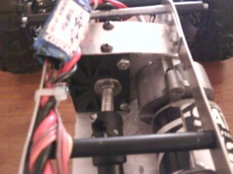 okay, i finally was able to get my pics working. this is the top view of it. you can see the aluminum rod i pressed in the tranny output. you can also see the motor plate/tranny plate flipped. the motor clearly hangs out of the chassis. chassis is 2.5'' wide. its more narrow then my tuber was. when i had the tuber setup it crawled very well being kinda on the wide. this rig i built has a very low cog. i can put it right on its side and it will stay. the motor hasnt gotten hit or hung up on anything yet. you could probably go narrower then mine, but with the spur hanging out a bit too. could make a little guard for it. down side is you would probably have to make new chassis plates. just play around with what you got first.just run it on the rocks and see how it acts, if you feel it needs changes then you will know where to start. you may be happy with it the way it is. when you had it in the more droop friendly pic, the motor didnt look overly high. 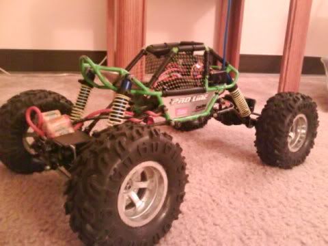 this was my goliath tuber. sitting on my crumby moabs. i had rock claws on it most of the time. boy those were a waste of money:-( they didnt stay on it to long before i switched back.  |
|
| |
|
02-14-2010, 08:32 PM
| #33 |
| Pebble Pounder Join Date: Jan 2010 Location: Glenview
Posts: 129
|
Josh that tuber looked great!!! I finished the modded gearbox plates, pics here: http://www.photoshop.com/accounts/5e...5457e39f8d82cf http://www.photoshop.com/accounts/5e...9872f5a68f415c http://www.photoshop.com/accounts/5e...981401011a2ae6 http://www.photoshop.com/accounts/5e...6fce2a760e5011 Each of the new gearbox plates are 2.5" wide instead of 2" as original. The spur/spool/bearings are moved down and to the side assuming no more than a 70 tooth spur and the motor/gru has been offset to the opposite side and moved down nearly .75". They are both .25" wide 6061 alu and the motor mount side has a 3rd pair of chassis bolts up near the top. There is now NO flex in motor mount/pinion/spur area. I successfully cleared the suspension link arms and still get full articulation. My CAM software crapped out so I haven't been able to cut the new bottom plate and the horizontal frame plate to hold the ESC and RX so they are mounted temporarily. |
|
| |
|
02-14-2010, 08:39 PM
| #34 |
| Pebble Pounder Join Date: Jan 2010 Location: Glenview
Posts: 129
|
In rummaging through my stuff I found a Rubicon body I did for my e-Revo a few years ago that I haven't been using (went back to the Silverado body on the Revo) and noticed that it seems a nearly PERFECT fit possibility. Now I'm torn between making this a scaler or a comp style (with the proline body I'm painting but not done with) Here's some pics of each, any thoughts from the crew? I'm still leaning towards the proline crowd pleazer because it looks sleek (or will when done). http://www.photoshop.com/accounts/5e...899418bcfdd3e0 http://www.photoshop.com/accounts/5e...2ceedf8f9f16e0 http://www.photoshop.com/accounts/5e...75d821056fc8b7 http://www.photoshop.com/accounts/5e...5bd0898e514193 http://www.photoshop.com/accounts/5e...3e0ce81e955400 |
|
| |
|
02-15-2010, 02:36 PM
| #35 |
| Rock Crawler Join Date: Jul 2009 Location: waterville
Posts: 525
|
that tranny plate is nice,i like how you offset it. doesnt look like the motor sits that high. i love that crowd pleazer body. it looks like it will crawl very well. i know i keep saying it but you can do some really nice work. wicked clean. |
|
| |
|
02-15-2010, 02:36 PM
| #36 |
| Pebble Pounder Join Date: Jan 2010 Location: Glenview
Posts: 129
|
Next steps: 1) finish the chassis plates and the electronics mounted in final places 2) Finish painting crowd pleazer body 3) Replace Fut 9001s with Hitec 5625s (these old Futabas are no good on this thing) 4) Replace steering linkages with something more robust, probably going to try heating and bending some alu rod 5) Pull axles apart, shim diffs and counter gears, epoxy bearings to housing spaces, and drill through bolt holes and tighten down diff cases 6) Suspension tuning. |
|
| |
|
02-15-2010, 02:41 PM
| #37 | |
| Pebble Pounder Join Date: Jan 2010 Location: Glenview
Posts: 129
| Quote:
I'm thinking now about a custom light set, I have a large batch of 15K mcd LEDs that might have a place on this rig somewhere, I might try making my own ALU floods... | |
|
| |
|
02-17-2010, 09:30 AM
| #38 |
| Pebble Pounder Join Date: Jan 2010 Location: Glenview
Posts: 129
|
OK, worked on the steering. Replaced the servos with Hitec 5625s. Before pic of the linkages: http://www.photoshop.com/accounts/5e...7cf753cb064fe3 Lots of slop, the old linkages flexed, just plain poor. I stole an idea from the PTi gallery here, and cnc'ed up some carbon steering knuckle extenders. After a trial run and some adjustments, I made a pair for each knuckle that fit pretty darn close to perfect. Even if the knuckle has a cracked screw hole, these basically compensate and extend the link arm hole out 3/8" from stock to allow a real linkage rod to be used. The only mod required is to drill a 1/8" hole exactly where the carbon extender line up hole is on the arm. I screwed one screw in on the original hole lined up everything, tightened up, popped the drill bit in my trusty Rigid and it went through easy. I then made up two alu tube rods as shown in the pics and finished the ends off with Dubro ball links. The carbon extenders sandwich the ball links and now everything lines up very nicely with full steering throw in each direction. http://www.photoshop.com/accounts/5e...84d227ebf077db No more slop in the steering! I also made some 8 and 10 mm steel stand offs and used those for the screws on the shocks and on the upper suspension links, putting the 3mm screws on the upper link ends through the axle casing completely to allow it to be tightened down nicely. I also finished the CF radio tray that fits in (tongue and groove style) into the chassis and it has a nice tight fit. http://www.photoshop.com/accounts/5e...bc870af15f50b7 Still need to epoxy the diff bearings but that is a messy job for another day, for now, I'm going to focus on finishing the body up and getting it ready to run enough to screw around in the basement a bit more. I'm also getting a bit of body/chassis torque rollnot much but enough to annoy me. I'm going to do a search on the squat/anti squat and suspension tuning to see if I can get some tips of use here. |
|
| |
|
02-18-2010, 01:00 PM
| #39 |
| Pebble Pounder Join Date: Jan 2010 Location: Glenview
Posts: 129
|
OK need advise, where should I start with trying to get rid of chassis roll from torque? Also after running this a bit, it's obvious that the diff spools and axle pinions need shimming and the bearings be epoxied in. Also I think the shafts have some play in the bearing race all leading to gear skipping on hard torque climbs. I'm thinking I need to red loctite the shafts into the bearing races and epoxy the bearings into the bearing seats in the axles. This is the kind of stuff we do in the heli world (where I'm really from) to get stuff running perfectly in high power setups... Anyone else had a novel solution for fixing gear skip or am I at the limits of what is possible with these axles? I'm officially crawler crazy. I was ebaying last night for Clod axles to start my next super crawler project. Since I'm a bit of an electronics wiz, I was going to build my on micro controller based dig unit for a two motor super class machine (and of course custom design and build a complete clod axle crawlwer). |
|
| |
|
02-18-2010, 01:03 PM
| #40 |
| Pebble Pounder Join Date: Jan 2010 Location: Glenview
Posts: 129
|
Also, anyone else tried the proline formed weights for the titus wheels? I'm thinking of getting them as 12oz in the front sounds like it would help immensely with weight transfer and traction on steep uphill climbs...
|
|
| |
 |
| |


 Linear Mode


