| |
| |||||||
 |
| | LinkBack | Thread Tools | Display Modes |
 01-23-2011, 08:42 AM
| #1 |
| Newbie Join Date: Jan 2011 Location: Ottawa
Posts: 31
|
Hello from Ottawa, Ontario, Canada and welcome to my Tamiya CR-01 Land Cruiser build thread. I am brand new to crawling... I haven’t owned anything radio controlled since I built a Tamiya Hornet back in the eighties.This is a hobby that really appeals to me and I’ve been thinking about getting into it for a while. My wife and I do a lot of camping with our six-year-old daughter and I thought that a crawler would be fun to bring along. I chose the CR-01 for a number of reasons.
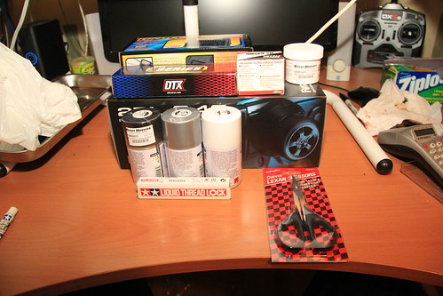
A Great Hobbies store opened in our neck of the woods in December and that’s where I purchased the CR-01 kit and almost all of the components and supplies. My wonderful wife went to them for the BNF Hobbyzone Super Cub LP she got me for Christmas, but that’s another thread. ;) During the build I took a lot of pictures. I thought about lumping the whole thing in a single post... too big. I thought about one post per step... too many. The best option remaining was to break it down into fair-sized chunks, so that’s what I decided to do. All of my build pics are posted together in one Flickr set. Most appear here in this thread with the captions beneath them. The pictures and captions are clickable - they launch a full-sized picture in a separate window or tab. And any time I have additional comments, they appear below the caption for that picture. Please also note that although I disagree with some of the wording, I am using the step titles specified in the Tamiya manual for the sake of consistency. Without further ado: 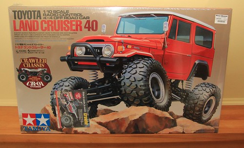 Tamiya Land Cruiser Love that box art! 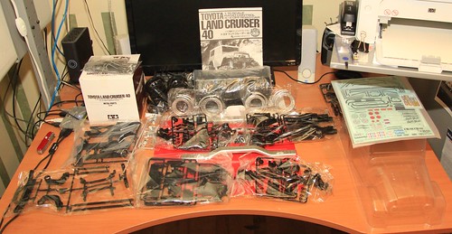 What's in the box Based on what’s in the manual, there are 1005 parts in the box... not including the manual itself. 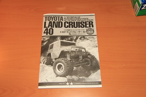 The book The manual is also available online. 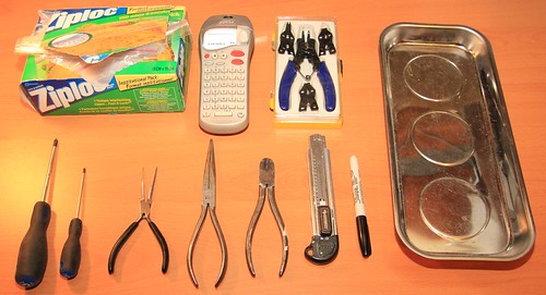 The tools Not shown: Large phillips screwdriver, toothpicks, tweezers, soldering iron (and accessories), wire stripping tool, magnetic wristband. Last edited by JD and Beastlet; 01-23-2011 at 09:01 AM. |

|  |
| Sponsored Links | |
| | |
|
01-23-2011, 08:43 AM
| #2 |
| Newbie Join Date: Jan 2011 Location: Ottawa
Posts: 31
|
Step 1 - Link mount 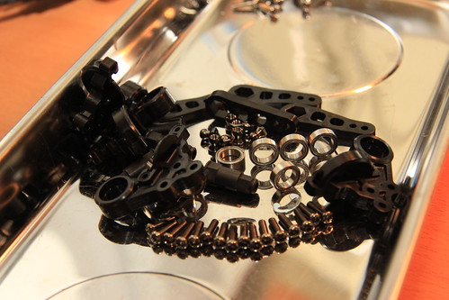 Step 1 (link mount) - parts 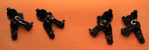 Step 1 (link mount) - completed Step 2 - Attaching link mount 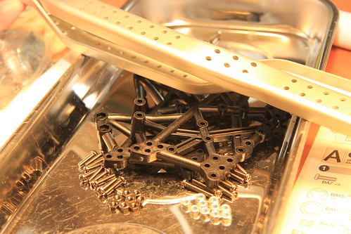 Step 2 (attaching link mount) - parts and hardware 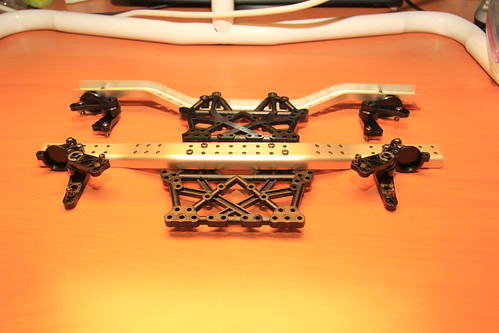 Step 2 (attaching link mount) - completed Step 3 - Mechanism deck 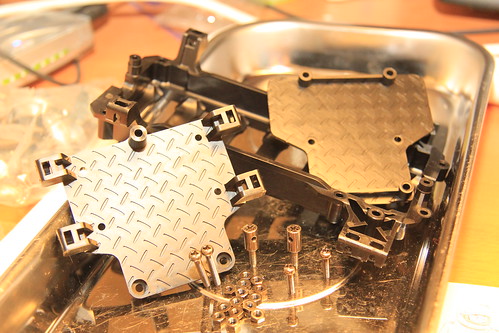 Step 3 (mechanism deck) - parts and hardware Forgot to take a picture of the completed mechanism deck... but you see it between the frame rails in the next step. Step 4 - Ladder frame 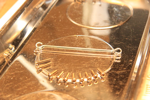 Step 4 (ladder frame) - parts and hardware 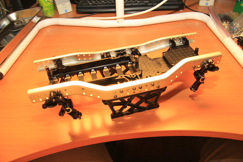 Step 4 (ladder frame) - completed There's the mechanism deck on the right. And the manual doesn't mention it, but it's a big help to stick some scotch tape over the nuts that are dropped into the slots of the battery case and the mechanism deck. Otherwise they'll just fall out... and they're tiny. I dropped a number of small parts during this build. I found every single one... I’m guessing divine intervention. Step 5 - Drive shaft 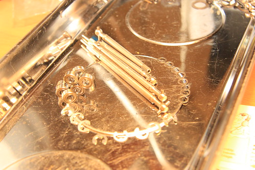 Step 5 (drive shaft) - parts and hardware 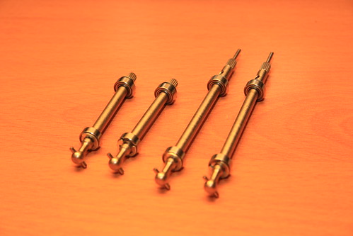 Step 5 (drive shaft) - completed Note the holes on the far end of the longer shafts. More on that in step 7. Step 6 - Differential gear 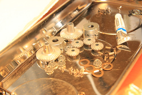 Step 6 (differential gear) - parts and hardware 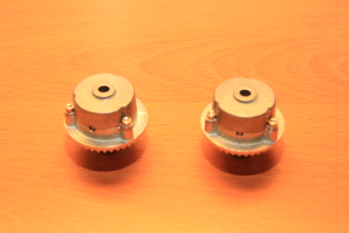 Step 6 (differential gear) - completed Step 7 - Axle housing 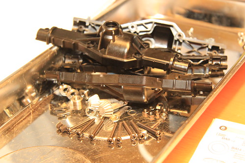 Step 7 (axle housing) - parts and hardware 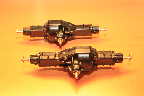 Step 7 (axle housing) - completed Everything went fine until I fastened the axle housings together. At that point the gears, which had previously run smoothly, began to bind and chatter. I did some research and found out that the gears turned freely when the differential locking pin was removed, because the pin was pulling the ring and pinions gears too close together. Some folks had success with backing the pins out a bit, but that didn't help me. Remember the holes in the shafts in step 5? I drilled those out a little larger and that solved the problem. Step 8 - Attaching suspension mount  Step 8 (attaching suspension mount) - parts and hardware 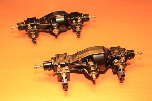 Step 8 (attaching suspension mount) - completed Be careful on this step. The axles, attachments and hardware all have to be facing the correct way, and the nuts and bolts need to go in the correct holes. There are endless combinations and only one of them is right. Don’t ask me how I know. :p Step 9 - Coil spring mount 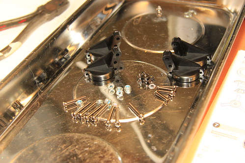 Step 9 (coil spring mount) - parts and hardware 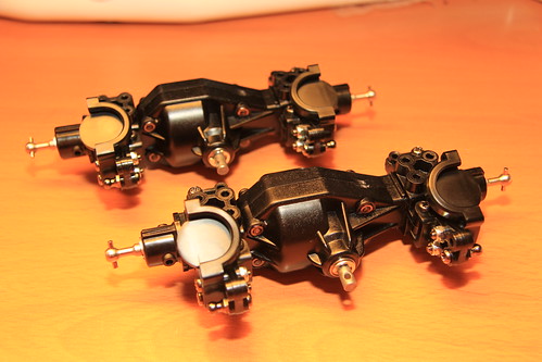 Step 9 (coil spring mount) - completed Step 10 - Upright 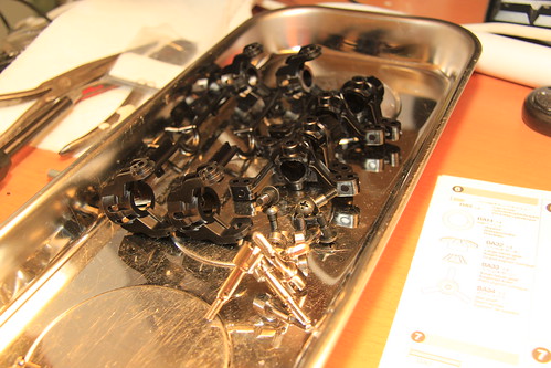 Step 10 (upright) - parts and hardware 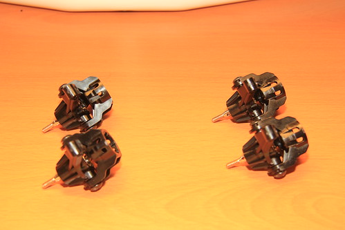 Step 10 (upright) - completed Step 11 - Attaching uprights 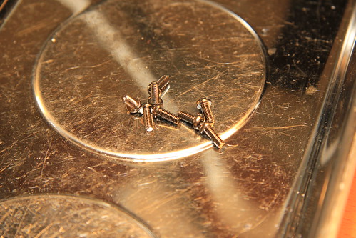 Step 11 (attaching uprights) - parts and hardware 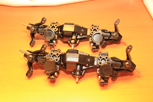 Step 11 (attaching uprights) - completed Last edited by JD and Beastlet; 01-23-2011 at 09:01 AM. |
|
| |
|
01-23-2011, 08:44 AM
| #3 |
| Newbie Join Date: Jan 2011 Location: Ottawa
Posts: 31
|
Before step 12 could be started, I needed to pick up the remaining parts for the truck. They are:
 More components, tools and supplies 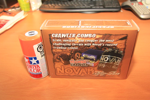 Speed controller / motor combo, orange paint Step 12 - Checking R/C equipment 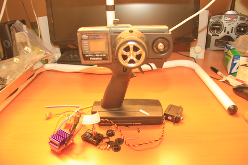 Step 12 (checking RC equipment) - parts and hardware 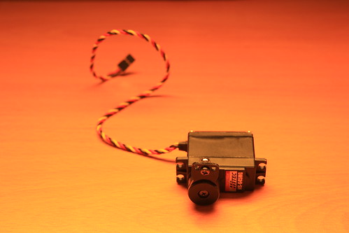 Step 12 (checking RC equipment) - complete Step 13 - Steering servo 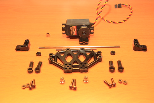 Step 13 (steering servo) - parts and hardware 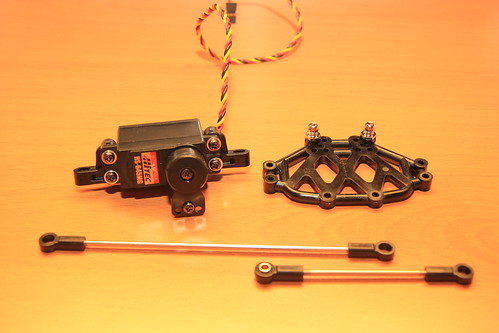 Step 13 (steering servo) - completed Step 14 - Attaching steering servo 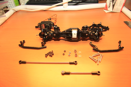 Step 14 (attaching steering servo) - parts and hardware 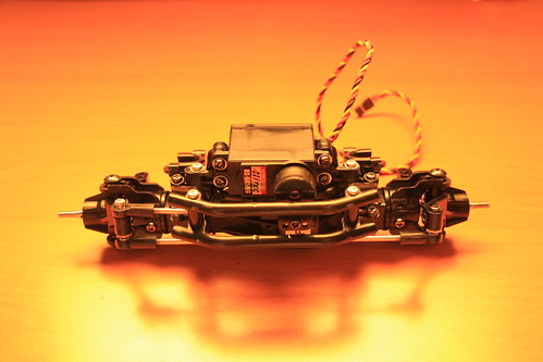 Step 14 (attaching steering servo) - completed Step 15 - Attaching rear tie-rods 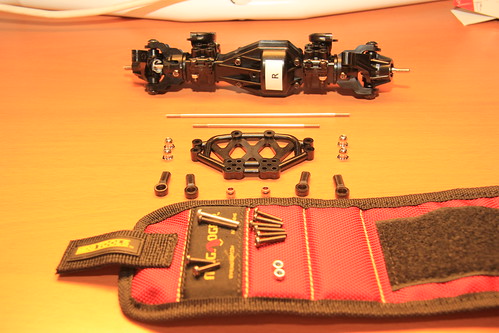 Step 15 (attaching rear tie-rods) - parts and hardware At this point it occurred to me to make use of my magnetic wristband, also an awesome gift from my wife. Very handy.  Step 15 (attaching rear tie-rods) - completed Four-wheel steering can be added as an option at this point. I’m sticking with stock in this regard, at least for now. Last edited by JD and Beastlet; 01-23-2011 at 09:02 AM. |
|
| |
|
01-23-2011, 08:44 AM
| #4 |
| Newbie Join Date: Jan 2011 Location: Ottawa
Posts: 31
|
Step 16 - Attaching axle housing 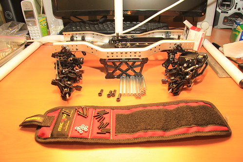 Step 16 (attaching axle housing) - parts and hardware 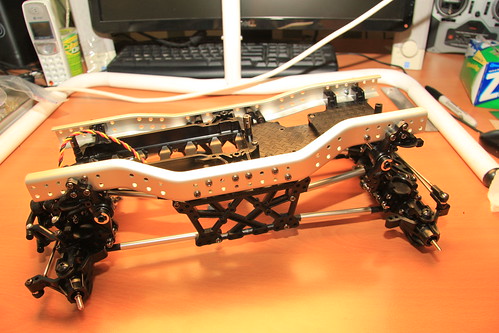 Step 16 (attaching axle housing) - suspension compressed  Step 16 (attaching axle housing) - suspension extended Step 17 - Damper 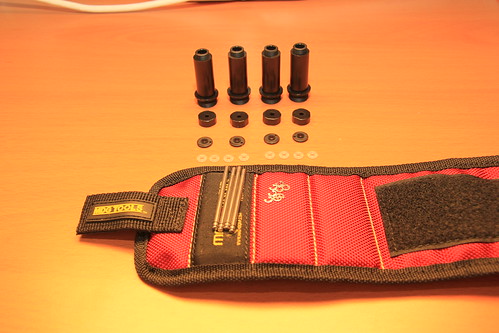 Step 17 (damper) - parts and hardware 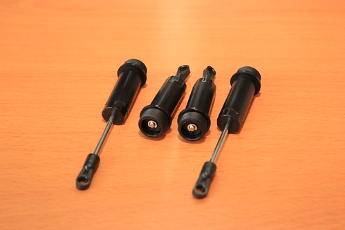 Step 17 (damper) - completed Step 18 - Damper oil 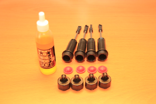 Step 18 (damper oil) - parts and hardware 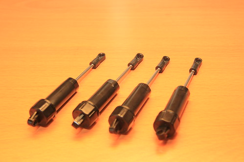 Step 18 (damper oil) - completed Step 19 - Attaching spring  Step 19 (attaching spring) - parts and hardware 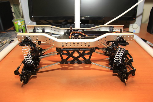 Step 19 (attaching spring) - completed Step 20 - Attaching dampers 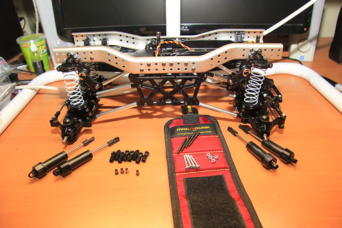 Step 20 (attaching dampers) - parts and hardware 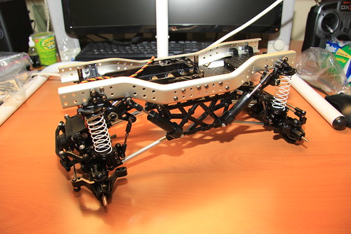 Step 20 (attaching dampers) - parts and hardware Last edited by JD and Beastlet; 01-23-2011 at 09:02 AM. |
|
| |
|
01-23-2011, 08:45 AM
| #5 |
| Newbie Join Date: Jan 2011 Location: Ottawa
Posts: 31
|
Step 21 - Propeller shaft 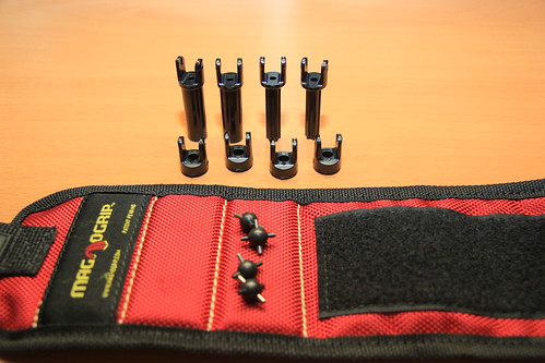 Step 21 (propeller shaft) - parts and hardware 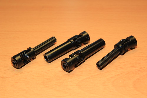 Step 21 (propeller shaft) - completed Step 22 - Planetary gear 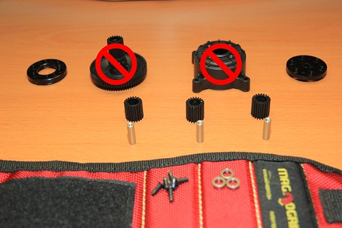 Step 22 (planetary gear) - parts and hardware The sun gear and outer gear appear in this photo by mistake; they are not actually used until steps 23 and 24.  Step 22 (planetary gear) - completed Step 23 - Attaching planetary gear 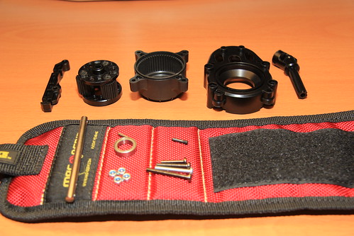 Step 23 (attaching planetary gear) - parts and hardware The outer gear shown with the parts and hardware for step 22 is used here. 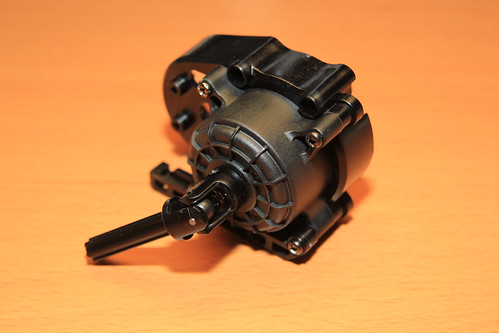 Step 23 (attaching planetary gear) - completed 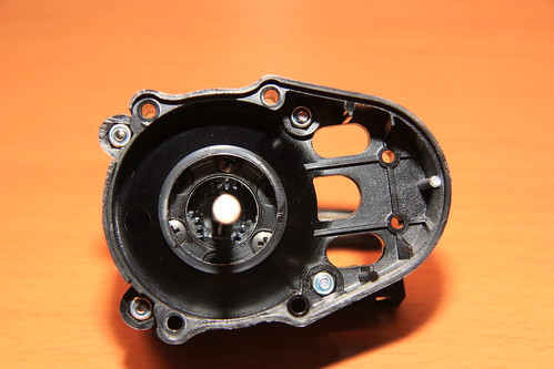 Step 23 (attaching planetary gear) - view inside Step 24 - Attaching motor 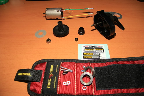 Step 24 (attaching motor) - parts and hardware At first I planned to use the original motor. Note the three capacitors soldered to the motor - they were included with the Novak ESC to prevent interference. 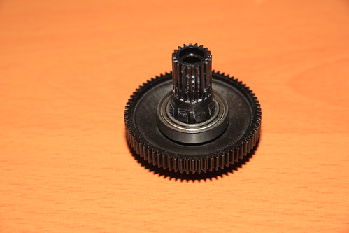 Sun gear used in step 24 Here’s the sun gear shown with the parts and hardware in step 22. Note the wider part on the bottom of the shaft - the two bearings (BD7) with shim (BD16) between had to be pressed onto the sun gear for it to fit inside the gear case. This was not specified in the manual. 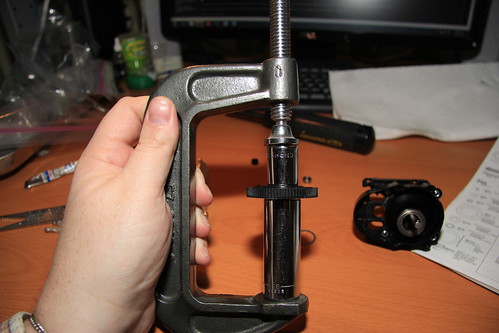 Step 24 (attaching motor) - pressing bearings onto sun gear shaft) I used two sockets in a large C clamp to press the bearings onto the sun gear shaft - a long 11/16” for the bearing side and a short 9/16” to distribute the load on the outer side. 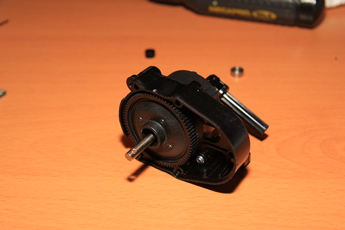 Sun gear properly inserted into gear case This is how the sun gear looks when it’s fully inserted into the gear case. 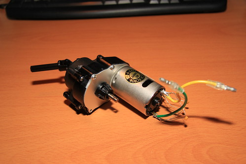 Step 24 (attaching motor) - completed When the sun gear fits properly the motor plate (BD-11) will fit properly into the gear case. Step 25 - Gear case 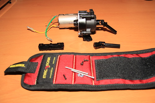 Step 25 (gear case) - parts and hardware 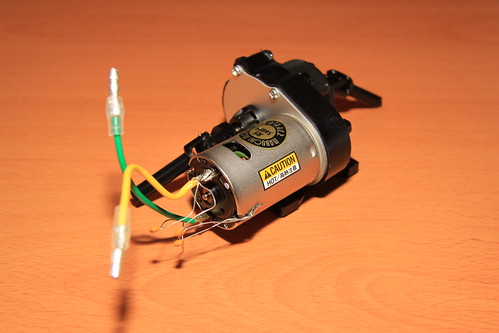 Step 25 (gear case) - completed Step 26 - Attaching motor Yes, this step does have the same name as step 24. 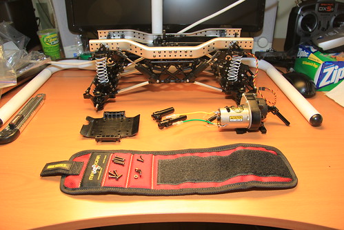 Step 26 (attaching motor) - parts and hardware 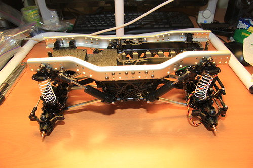 Step 26 (attaching motor) - complete 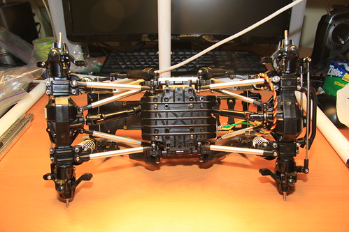 Step 26 (attaching motor) - bottom view Step 27 - Attaching R/C unit 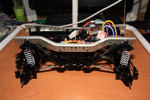 Step 27 (attaching rc unit) - complete 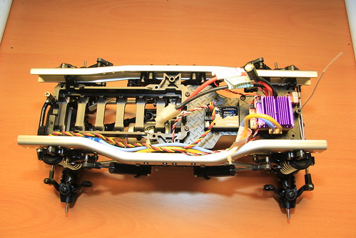 Step 27 (attaching rc unit) - from top 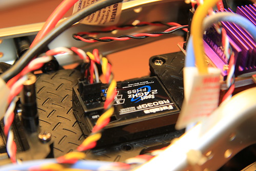 Step 27 (attaching rc unit) - receiver  Step 27 (attaching rc unit) - ESC from rear 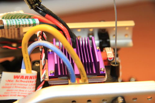 Electronic speed controller Step 28 - Cross member 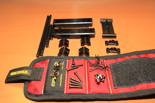 Step 28 (cross member) - parts and hardware 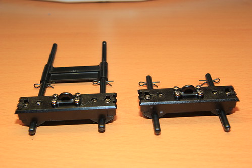 Step 28 (cross member) - complete Step 29 - Attaching cross member 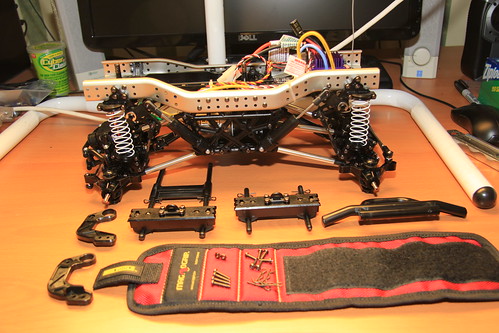 Step 29 (attaching cross member) - parts and hardware 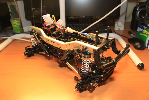 Step 29 (attaching cross member) - complete Step 30 - Wheel assembly 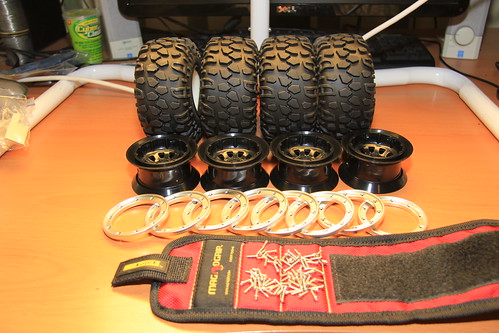 Step 30 (wheel assembly) - parts and hardware There are eighty screws here. EIGHTY. I recommend using a power driver on the lowest torque setting. 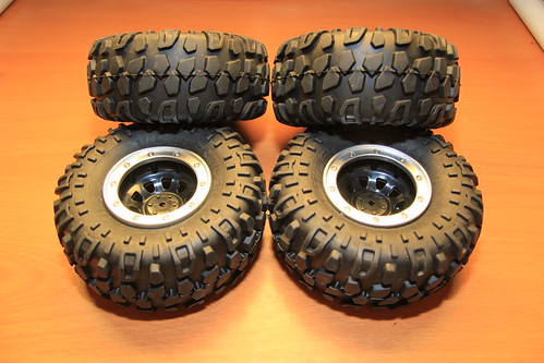 Step 30 (Wheel assembly) - complete Step 31 - Attaching wheels 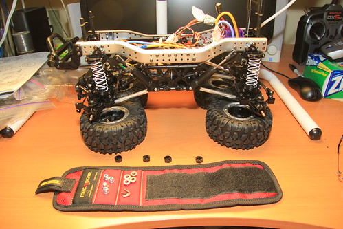 Step 31 (attaching wheels) - parts and hardware  Step 31 (attaching wheels) - complete 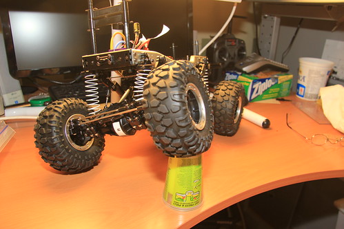 Obligatory articulation shot Step 32 - Installing battery 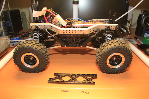 Step 32 (installing battery) - parts and hardware 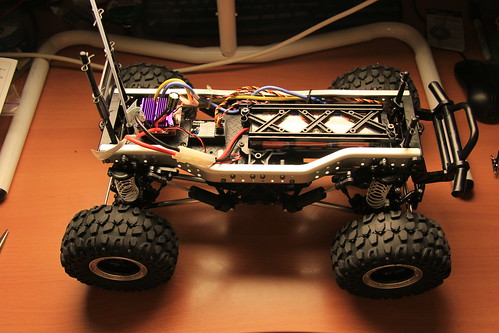 Step 32 (installing battery) - complete Now the mechanical part is done. A brief run in the house to make sure everything works... then on to the body! Last edited by JD and Beastlet; 01-23-2011 at 09:03 AM. |
|
| |
|
01-23-2011, 08:51 AM
| #6 |
| Newbie Join Date: Jan 2011 Location: Ottawa
Posts: 31
|
Step 33 - Trimming and painting body This is a big step, so I’ve split it into three... Trimming, masking and painting. Trimming 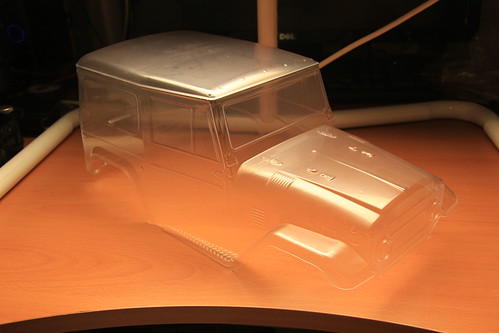 Step 33 (trimming and painting body) - trimmed Though the manual shows the body being painted before trimming, I chose the opposite order based on some advice I received. I bought polycarbonate scissors for this step but after a little research I decided to tackle it with a utility knife. I used a fresh blade segment and scored lightly along the seam lines... and with a little folding back and forth the waste separated cleanly. 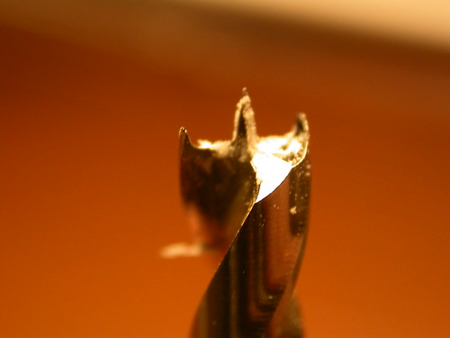 Brad point drill bit for body holes Now for the holes. I don’t have a reamer so I decided to use brad point drill bits. The centre point is great for locating the holes and the spurs cut the side cleanly. I started by spinning the bit with my fingers, then chucked it in a small hand-operated drill I have. 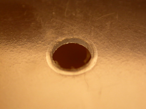 Body hole Nice neat holes. 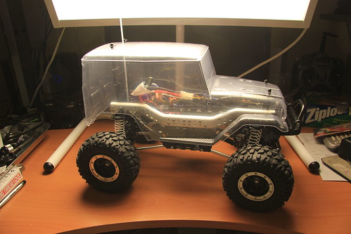 Step 33 (trimming and painting body) - body mounted A little test fit... perfect. Masking 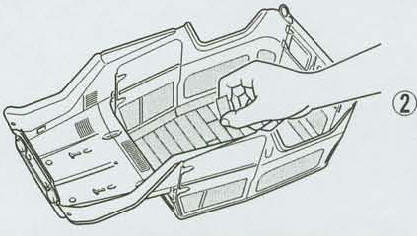 Suggested masking of roof This is the method shown in the manual. I had too much trouble getting the tape into the seams. 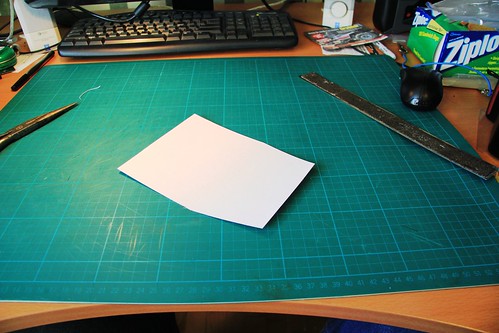 Step 33 (trimming and painting body) - roof template cut I decided to use cardstock, tape and liquid mask. First step - cardstock template, a bit smaller than the roof so I could tape around it. 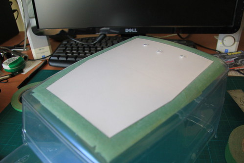 Step 33 (trimming and painting body) - roof template masked in Second step - taping it in. 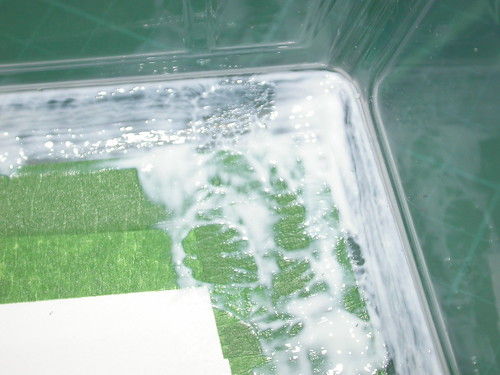 Step 33 (trimming and painting body) - cardstock mask, masking tape and liquid mask Third step - liquid mask to the edges. 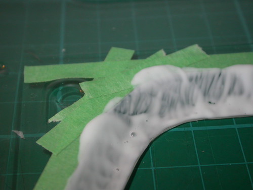 Step 33 (trimming and painting body) - masking the fenders Using masking tape to define the lines of the liquid mask works well... as long as you peel the tape off right away. 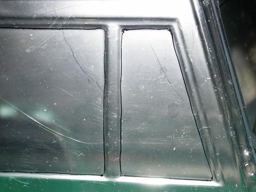 Step 33 (trimming and painting body) - outlined windows I used a pen to outline the windows... a suggested technique for helping to place the window masks. 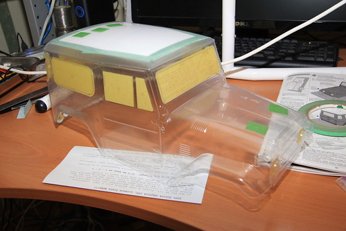 Step 33 (trimming and painting body) - windows masked, front Masking complete - time to shoot paint! Painting I used Tamiya paint for polycarbonate. It has a very strong smell so make sure you’re working in an area with adequate ventilation. For me that meant my basement workshop with a box fan drawing air out of an open window, and the furnace turned off to avoid the spreading fumes throughout the house. I wore a dust mask but it didn’t do much to keep out the smell. A proper respirator would have been much better but for the little exposure I got I wasn’t worried. I’ve never spray-painted polycarbonate before so I did a little research. Two forum posts proved very helpful... props to prestonlal and Willystylz. One of the tips sped up the job considerably... use of a blow drier between coats. 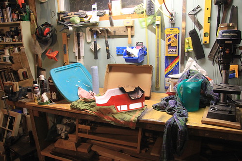 Step 33 (trimming and painting body) - Set up for painting My basement workshop, where I’m doing the painting. As you can see, I shot this photo when I was just about done. 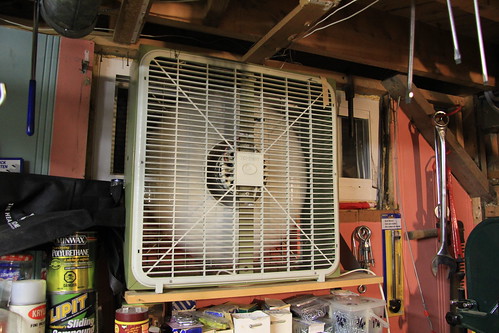 Step 33 (trimming and painting body) - ventilating the workshop 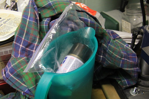 Step 33 (trimming and painting body) - keeping the paint warm First part - body colour 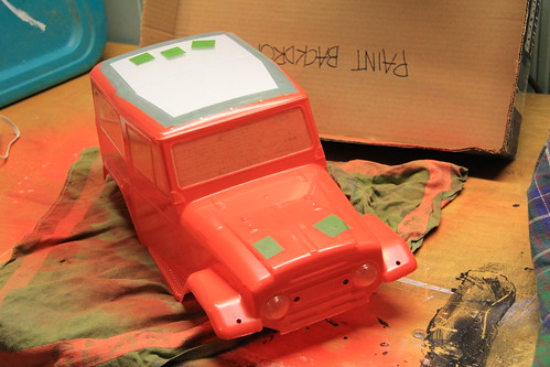 Step 33 (trimming and painting body) - base orange coat, front Second part - roof and inner coat 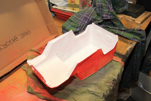 Step 33 (trimming and painting body) - white paint in Third part - fenders and bumper 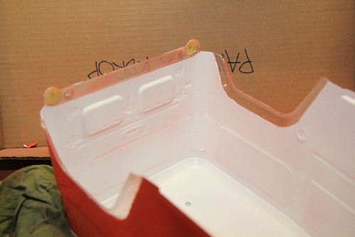 Step 33 (trimming and painting body) - liquid mask all removed The liquid mask came off pretty easily. I used my fingernails to get the stubborn bits, and I wiped the transparent parts with a damp microfibre cloth to remove and residue. The dusting of orange visible where the mask has been removed is overspray on the protective film covering the outside of the body. 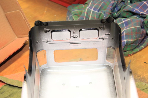 Step 33 (trimming and painting body) - Rear fenders and bumper painted At this point I’ve removed the window masks as well. Fourth part - windows 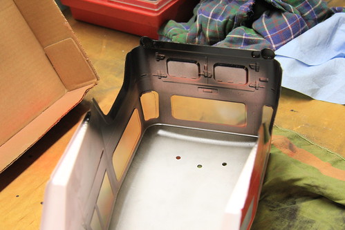 Step 33 (trimming and painting body) - windows tinted I wasn’t sure how well this would work but I was amazed at the effect - I gave it three light coats for a light tint. Painting complete! 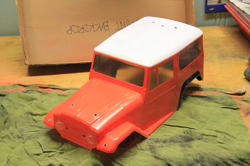 Step 33 (trimming and painting body) - painting complete The body painting is complete. For a first effort I’m very pleased with the results. 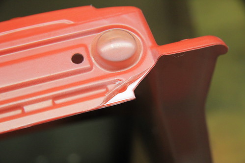 Step 33 (trimming and painting body) - a peek under the film I couldn’t resist a peek under the protective film. It’s like night and day!  Step 33 (trimming and painting body) - protective film off The next morning the three of us peeled off the protective film together. Love that gloss... it’s like the paint has 50 layers of clearcoat. 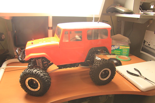 Step 33 (trimming and painting body) - test fit Next step... stickers. Last edited by JD and Beastlet; 01-23-2011 at 09:04 AM. |
|
| |
|
01-23-2011, 08:53 AM
| #7 |
| Newbie Join Date: Jan 2011 Location: Ottawa
Posts: 31
|
Step 34 - Marking When I first opened the box and saw the sticker sheet with its pale blue backing I assumed they were water-release decals of the type you’d find in a plastic model kit. Wrong! Well, at least they’d be scored for easy removal. Wrong again! You have to cut each sticker out individually. Note also that some of the stickers are very finicky. To start with I’m only going to apply the stickers specified in the manual - the ones that make the body look like a stock Land Cruiser. The sponsor stickers can wait. 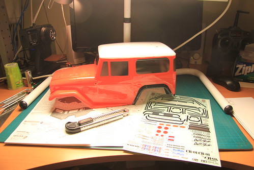 Step 34 (marking) - parts 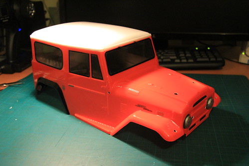 Step 34 (marking) - complete Some of the stickers went on well and some, not so well. I did the best I could and I’m satisfied with the results. Some tips:
My least favourite part of the build. Glad it’s done. Step 35 - Attaching taillights I might purchase and install the LEDs later. For now it’s just a matter of attaching the stock parts to the body.  Step 35 (attaching taillights) - parts and hardware 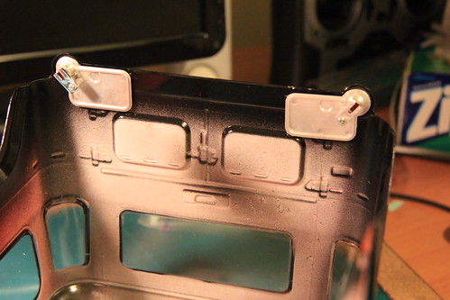 Step 35 (attaching taillights) - completed Step 36 - Attaching front grille 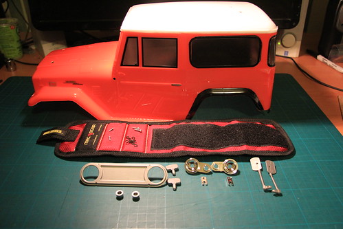 Step 36 (attaching front grille) - parts and hardware 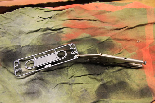 Step 33 (trimming and painting body) - Paint the grill and signal lights I painted the grill and signal lights while still on the sprue. I used a small pair of vise grips so I could paint both sides. I covered the vise grips with a shop towel while painting. 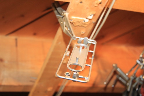 Step 33 (trimming and painting body) - Drying the grill The vise grips made it handy to hang the rack for drying, too. 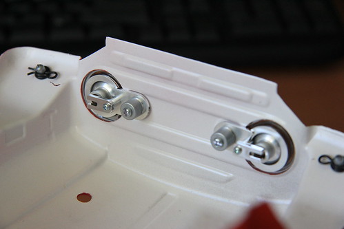 Step 36 (attaching front grille) - light buckets 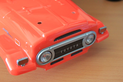 Step 36 (attaching front grille) - grill and signal lights 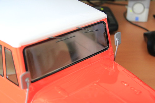 Step 36 (attaching front grille) - mirrors Step 37 - Attaching body 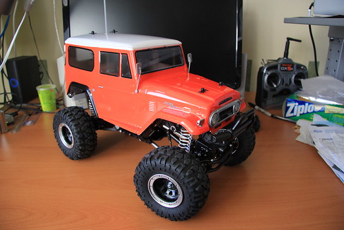 Completed - three quarter front passenger side 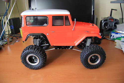 Completed - passenger side 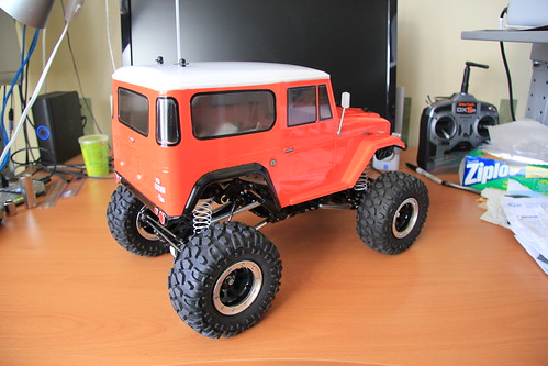 Completed - three quarter rear passenger side  Completed - rear 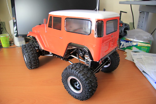 Completed - three quarter rear driver's side 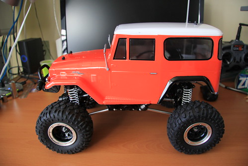 Completed - driver's side 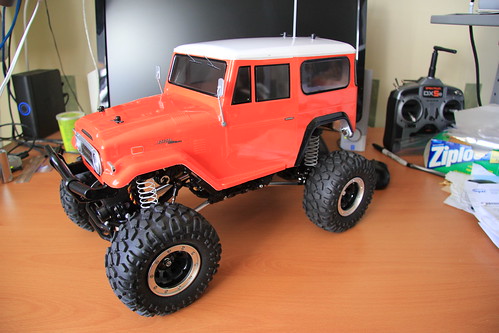 Completed - three quarter front driver's side 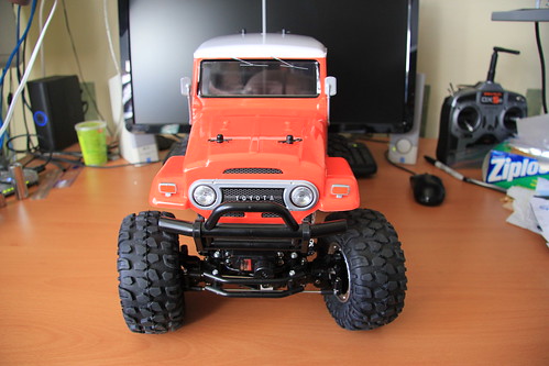 Completed - front Stock build... done! Time estimates: Mechanical and electrical - 10 hours Trimming and masking - 2 hours Painting - 2 hours Stickers - 4 hours Total - 17 hours Last edited by JD and Beastlet; 01-23-2011 at 09:06 AM. |
|
| |
|
01-23-2011, 09:13 PM
| #8 |
| Quarry Creeper Join Date: Jan 2010 Location: vancouver, canada
Posts: 309
|
fantastic documentation! thanks for this, i think it should be stickied!
|
|
| |
|
01-24-2011, 06:16 AM
| #9 |
| Rock Crawler Join Date: Mar 2010 Location: NRV
Posts: 958
|
Very nice build thread. Anyone building their first Cr01 would find this helpful
|
|
| |
|
01-24-2011, 05:45 PM
| #10 |
| Quarry Creeper Join Date: Jan 2010 Location: vancouver, canada
Posts: 309
|
agreed, now get it dirty!
|
|
| |
|
01-25-2011, 06:30 AM
| #11 |
| Rock Crawler Join Date: Mar 2010 Location: NRV
Posts: 958
|
I guess in Ottawa that could be a while.
|
|
| |
|
01-25-2011, 07:46 AM
| #12 |
| Newbie Join Date: Jan 2011 Location: Ottawa
Posts: 31
|
It's supposed to go up to -5ºC (21ºF) tomorrow. That should be good enough. |
|
| |
|
01-25-2011, 11:13 AM
| #13 |
| Quarry Creeper Join Date: Jan 2010 Location: vancouver, canada
Posts: 309
|
oh man, i did not consider that! hey, it's great on snow!
|
|
| |
|
01-26-2011, 06:14 AM
| #14 | |
| Rock Crawler Join Date: Mar 2010 Location: NRV
Posts: 958
| Quote:
| |
|
| |
|
02-16-2011, 08:40 PM
| #15 |
| Quarry Creeper Join Date: Mar 2010 Location: Massachusetts
Posts: 394
|
Awesome job! I've been looking into a cr-01 kit for a while, and I love the tamiya kits for their builds. How is it durability wise? My cars have a tendency to spend some time on their roofs...
|
|
| |
|
02-18-2011, 10:21 AM
| #16 |
| Quarry Creeper Join Date: Jan 2010 Location: vancouver, canada
Posts: 309
|
it's a tough chassis, just upgrade the drive shafts and your good to go. p.s we need this thread locked and stickied! |
|
| |
|
02-21-2011, 11:09 AM
| #17 | |
| Newbie Join Date: Jan 2011 Location: Ottawa
Posts: 31
| Quote:
Mine has been on its sides and roof more than once. Nothing has broken and there are no issues with the body. | |
|
| |
|
04-29-2011, 12:23 AM
| #18 |
| Newbie Join Date: Apr 2011 Location: aptos
Posts: 42
|
During my build, I noticed that the front axle required a hub that tilted 15 degrees inward (toward center of chassis), while the rear end required a 25 degree tilt; there were two possible positions, so I chose the more extreme angle for the 25-degree. Did you have any issues with this? It took me a while to realize that the two bearings had to be pressed onto the sun gear in the tranny; I read and re-read the instructions, till I eventually figured it out. Great posts! Thanks. |
|
| |
|
04-29-2011, 01:16 PM
| #19 |
| Quarry Creeper Join Date: Oct 2010 Location: Grandview, IA
Posts: 356
|
I'll be pickijg up a CR01 in the near uture and this thread was great. I really know what I'm getting into now build wise. It's been over a decade since I put together a kit lol
|
|
| |
|
05-02-2011, 06:29 AM
| #20 | |
| Newbie Join Date: Jan 2011 Location: Ottawa
Posts: 31
| Quote:
| |
|
| |
|
| |


 Linear Mode


