| |
 10-19-2011, 09:42 PM
| #1 |
| Quarry Creeper Join Date: Aug 2005 Location: Jefferson City
Posts: 345
|
...or that's the best name I could come up with so far.  Specs:
I've been rocking a DIY version of a BMVII for about 6 years now and decided that it was time to change things up a bit. I been seeing some very impressive chassis being developed for MOAs, but the shaft-driven world has been overlooked, for the most part. There were two chassis that kept drawing me in for a closer look...the Mantis and the Dahu. Both use MOAs (Bergs) but the overall design really intrigued me with the arches and the high clearance rear links. The more I looked at them, the more I wanted to design a chassis for my TLT axles with similar features. Thus begins the build. I drew the chassis out in AutoCAD, playing with the curves and driveline angles to see if it was even possible. Once the design was finalized, I cut templates out of cardboard. The chassis plates are made from 1/8" Lexan and the rear links, rear mount, skid plate and ESC top plate are made from cutting board. I used a plexiglass blade in my jigsaw to cut all the pieces out, so be NICE. 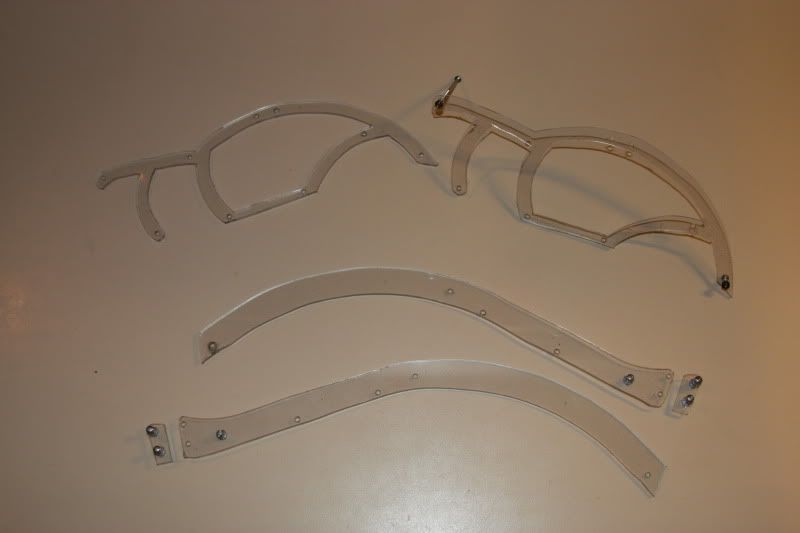 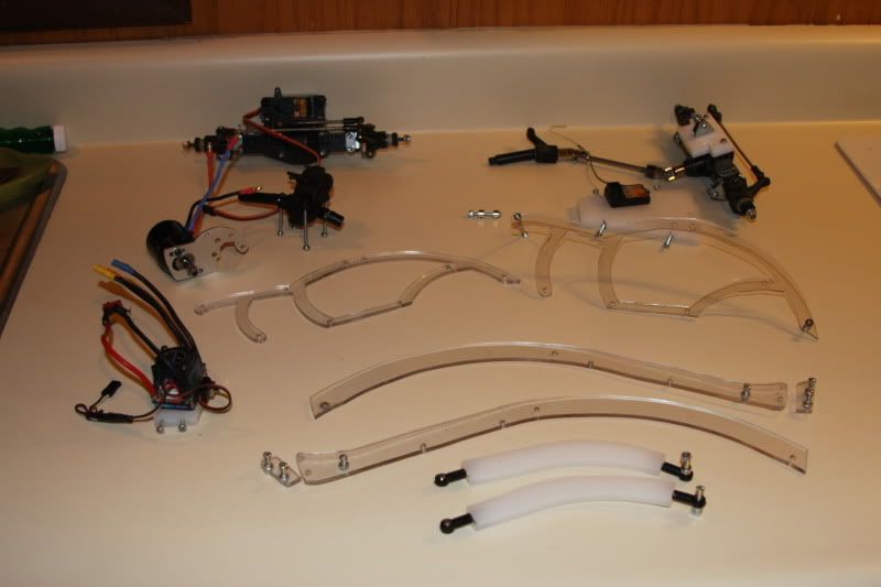 Transmission is a Traxxas Mini Summit with the idler and top gear swapped to give me an internal ratio of 3.74:1. I plan to use a 55-tooth spur and 14-tooth pinion. 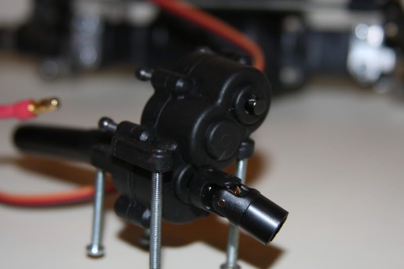 Motor is a Holmes Hobbies Revolver Black Outrunner. I created my own mounting plate. You can buy a motor plate for the transmission that will work with a 540 motor, but the motor sits too high. Plus, it costs $30 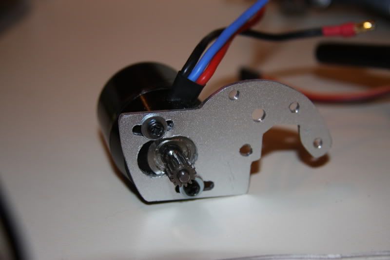 The front axles utilize clocked Cs that KC_Jones was kind enough to develop for me. In addition, I added bearings left over from my old TLT kit in the Cs for the knuckle screws. 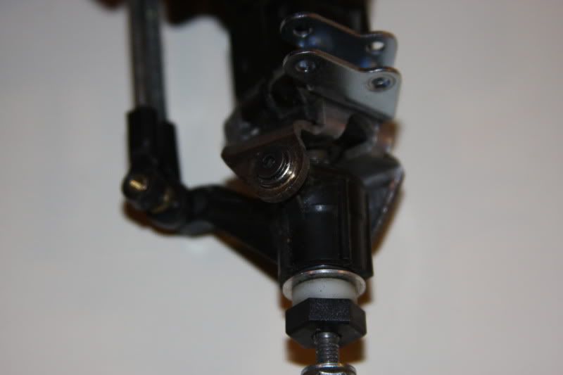 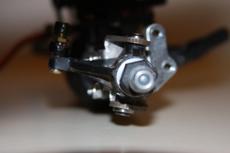 Last edited by bugman72; 10-20-2011 at 06:14 AM. |

|  |
| Sponsored Links | |
| | |
|
10-19-2011, 09:50 PM
| #2 |
| Quarry Creeper Join Date: Aug 2005 Location: Jefferson City
Posts: 345
|
Now, to put this all together... First thing to go together are the two side plates. These are the "backbone" of the chassis and where the torsional flex will come from. I used TLT hardware to mount the plates to the axles. Seen in the pictures is the rear driveline assembly, including the carrier bearing. 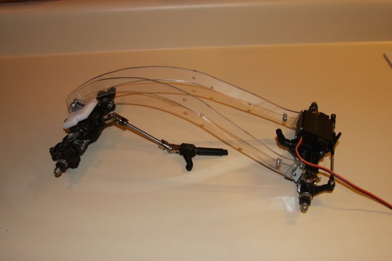 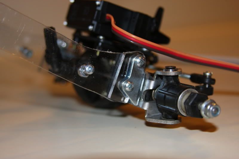 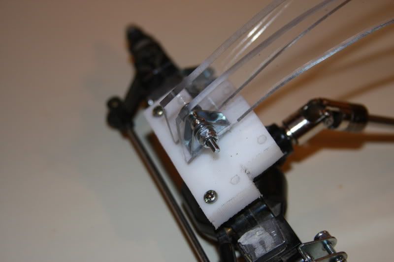 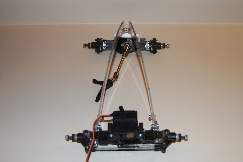 Next on the agenda are the rear links. I wanted them to follow a high arch for ground clearance, but at the same time protect the rear driveline as much as possible. I cut the link bodies from cutting board and then screwed 6-32 all-thread in each end. Link ends are currently Tamiya pieces from the TLT kit, but I will more than likely replace them with some Traxxas or Losi ones. Once again, the links were mounted to the rear axle using TLT brackets. 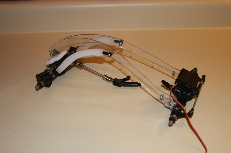 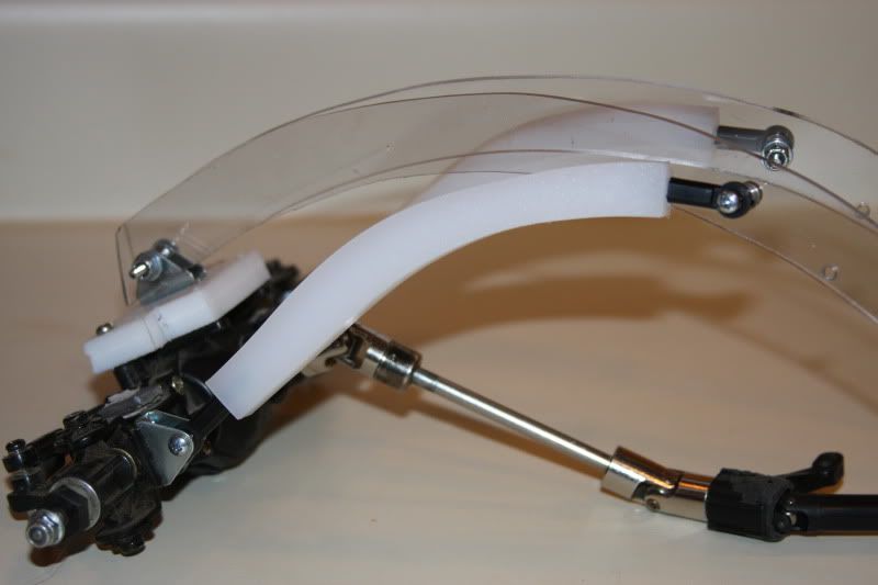 |
|
| |
|
10-19-2011, 10:04 PM
| #3 |
| Quarry Creeper Join Date: Aug 2005 Location: Jefferson City
Posts: 345
|
Here is the "body" that I designed. As you might be able to tell by my username, I'm a fan of VWs. I wanted the body to resemble a Bug while still having a unique look. I designed the body panels to aide in rollovers. When the truck turns on it's top, there is ALWAYS at least two wheels on the ground. 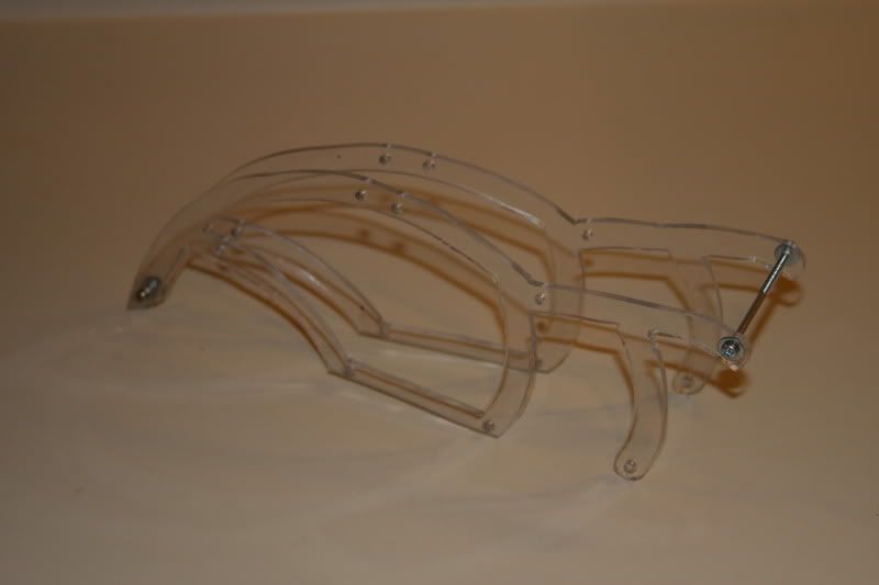 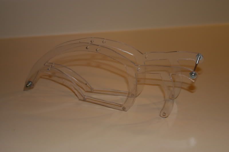 Attaching these to the previous assembly requires me to add the skid plate as well. As mentioned before, the skid is made from a section of cutting board. 4-40 screws pass through the body panels, then the main side plates and into the skid plate. 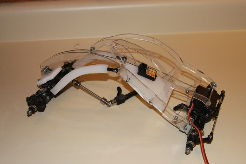 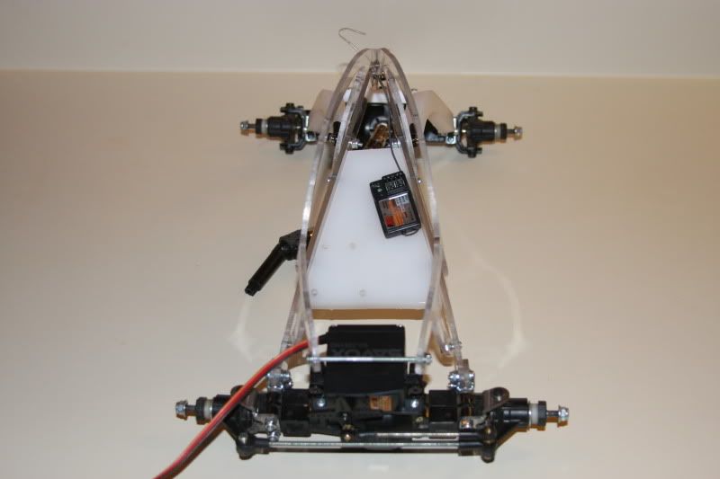 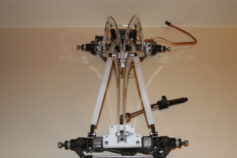 |
|
| |
|
10-19-2011, 10:15 PM
| #4 |
| Quarry Creeper Join Date: Aug 2005 Location: Jefferson City
Posts: 345
|
Transmission is next. I chose to run Mini Summit driveshafts in the front section to save precious space. I hope I'm not disappointed in their performance. The yolk that mates up to the carrier bearing as well as the one on the output shaft of the front axle have been bored out to 5mm (stock is 4mm). As mentioned before the idler and top gear have been swapped in the transmission. Stock setup gives an internal ratio of 1.94:1. By swapping the gears, I am able to get a 3.74:1 internal ratio. A 55-tooth spur will be used along with a 14-tooth pinion. The 55-tooth spur is the largest spur that can be installed on this transmission. 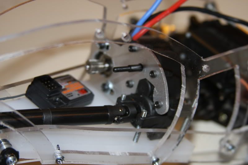 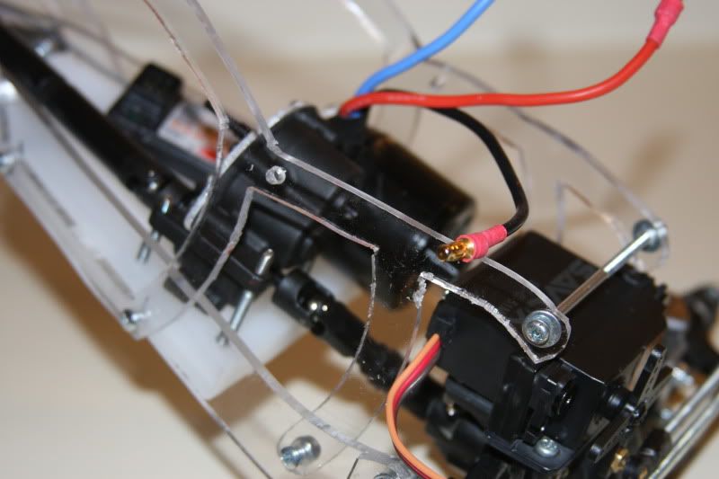 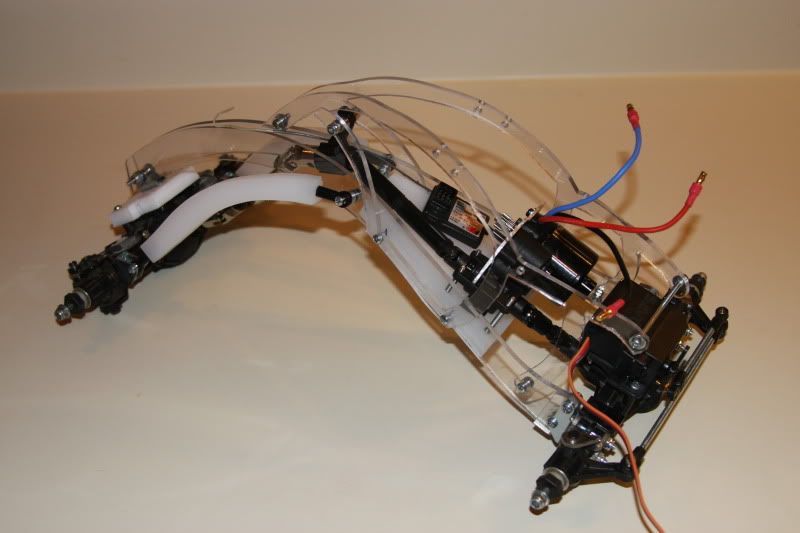 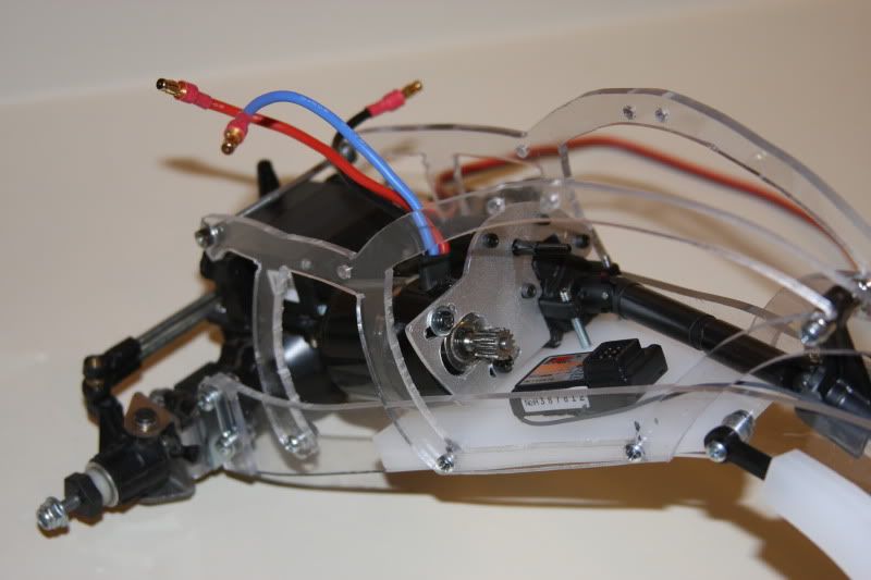 Here is a closeup of the carrier bearing assembly. I used a TA04 steering knuckle and cut a small piece from the CC-01 metal driveshaft as the carrier shaft. 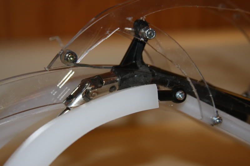 Underside of chassis showing skid plate and driveshafts. 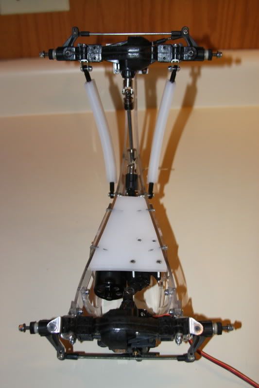 Last edited by bugman72; 10-20-2011 at 06:15 AM. |
|
| |
|
10-19-2011, 10:22 PM
| #5 |
| Quarry Creeper Join Date: Aug 2005 Location: Jefferson City
Posts: 345
|
With the build wrapping up and me still having most of the electronics NOT installed, I started to wonder if I was going to be able to get everything in the chassis area. My goal from the beginning has always been to try and keep all of the weight as low as possible and as far forward as possible. Thank goodness my ESC isn't very large. I tried for a couple of days to figure out where to put the ESC and still have room for the battery. I finally came up with mounting the ESC on the "roof". A plate made from cutting board was positioned so that the weight was still forward as much as possible and still allow for a "windshield area" once I create a hood. I really think that this ended up turning out perfect. On/off switch is currently mounted to the ESC and is easy to access, but still protected in the event of a rollover. 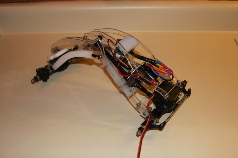 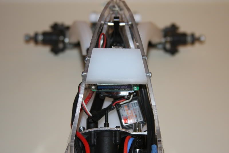 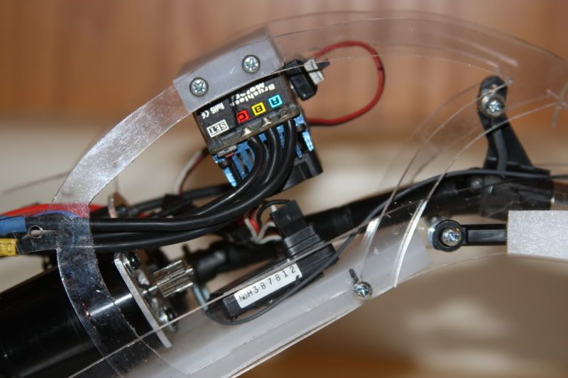 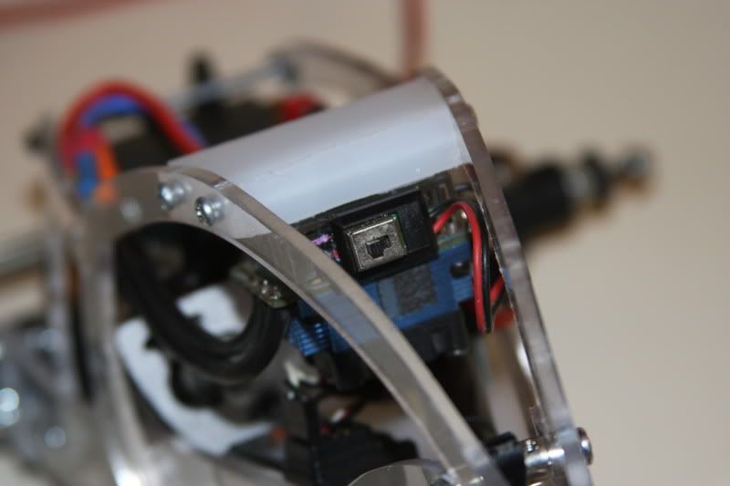 |
|
| |
|
10-19-2011, 10:33 PM
| #6 |
| Quarry Creeper Join Date: Aug 2005 Location: Jefferson City
Posts: 345
|
Alrighty, here's the semi-final product. I'm running 2.2 White Dot Rovers all around with factory foams. I am still working on a hood to cover and protect the Lipo. Plan is to do a cowl induction style hood, where the scoop is where the battery sets. It will be hinged at the bottom via zipties and will close with studs and mini body clips just below the windshield area. 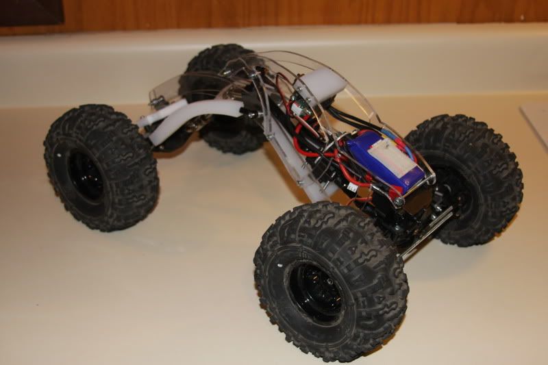 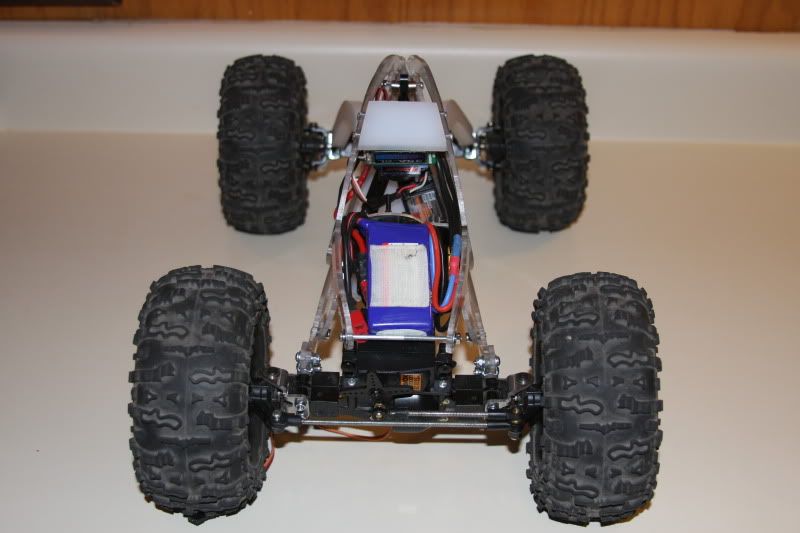 Now, about ground clearance. I think I have JUST a bit. 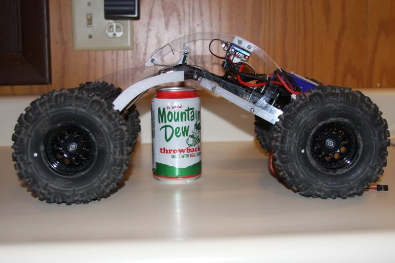 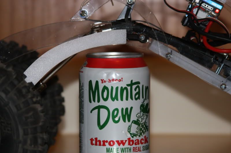 Flex? It's a torsion, so it's not going to have TONS, but I believe it has plenty. A change to different link ends on the rear will help to increase flex as well. 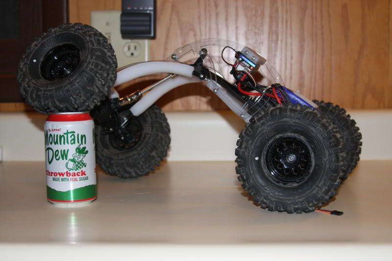 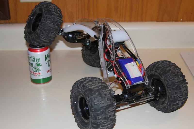 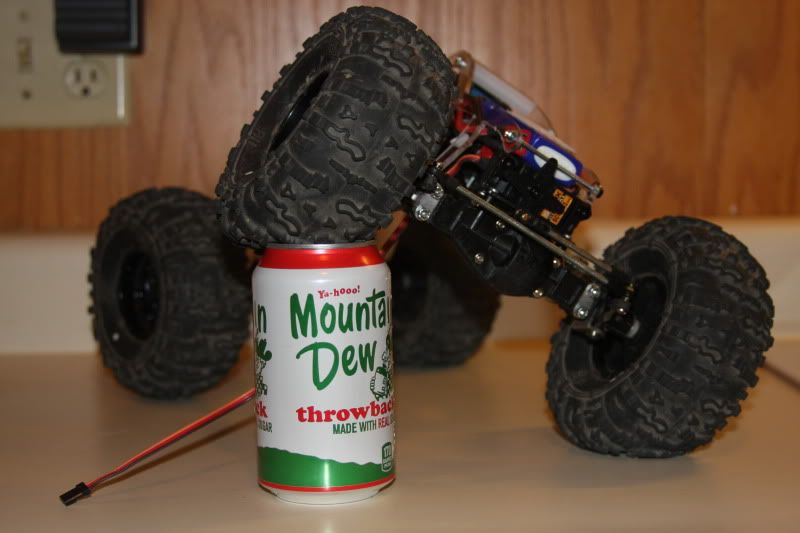 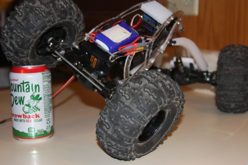 Now, with all of that ground clearance, won't it be top-heavy? I thought it might. The pictures tell me different. This is a 10" high hearth. Rear tires are touching the wall and the ground. Front tires are firmly planted as well. 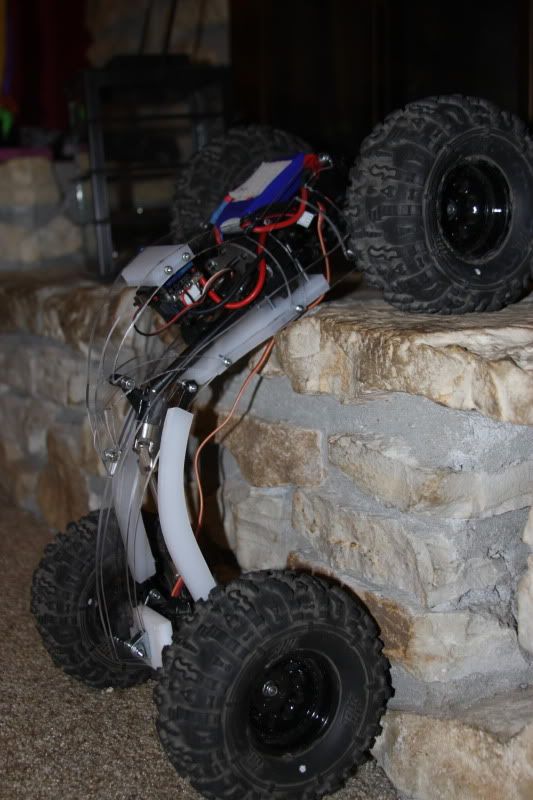 How's this for a pic? 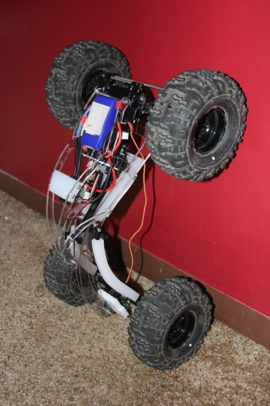 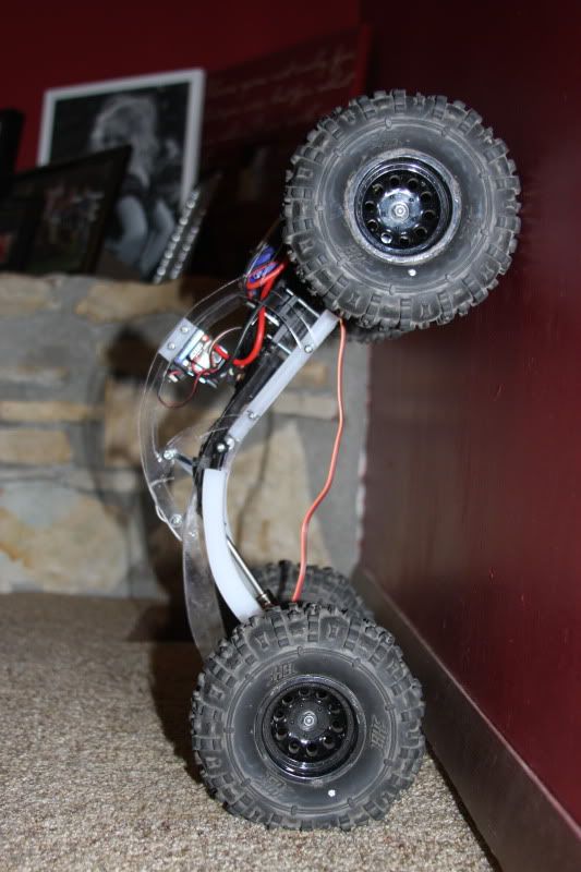 It was hard to tell exactly how close the rear tires were from the wall, so I grabbed my cutting mat and placed it beneath the tires. The beginning of the measure is right at the trim. 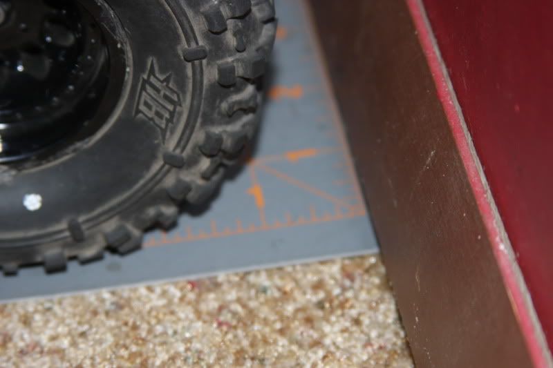 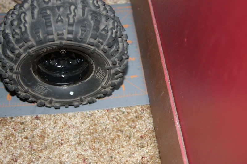 Yeah, that's less than 1"!! 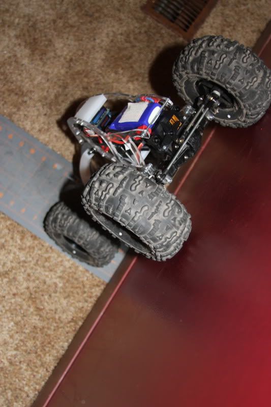 |
|
| |
|
10-19-2011, 10:39 PM
| #7 |
| Quarry Creeper Join Date: Aug 2005 Location: Jefferson City
Posts: 345
|
Now, how it actually does on the rocks has yet to be seen. I should be getting the slipper clutch assembly and spur gear on Friday. I hope to have some time over the weekend to try the truck out to see if I encounter any major issues. I'm pretty sure that I'll need to add some weight to the rear. Currently I'm running about 8 oz in each front tire and none in the rear. That's how my BMVII seemed to work best. I will probably add at least a couple of oz in each rear tire, but I want to see how it runs as-is first. Hopefully my gearing works out. I know the final rollout ratio is almost identical to the BMVII running a Evader Pro tranny and an 87/14 combo. Only time will tell. Hopefully you have been able to follow my ramblings during this build. I am very pleased with the results so far and wanted to show the RCC community. Hopefully, if all goes well I can have some videos to post up around the first of next week. Any comments, questions, suggestions? Let me know. |
|
| |
|
10-20-2011, 12:36 AM
| #8 |
| Quarry Creeper Join Date: Dec 2009 Location: in front of you...
Posts: 248
|
awesome! i cant wait to see vids of it in action...
|
|
| |
|
10-20-2011, 06:28 AM
| #9 |
| RCC Addict Join Date: Aug 2007 Location: Marshalltown
Posts: 1,003
|
Use of a carrier bearing driveshaft... shafty Mantis style chassis... Homebuilt.... HH revolver motor... I love it all. Good work. I am excited to see how this will work on the rocks for you. I'm sure it will be good but please keep this updated and show everyone you don't have to buy everything. |
|
| |
|
10-20-2011, 06:35 AM
| #10 |
| Quarry Creeper Join Date: Aug 2005 Location: Jefferson City
Posts: 345
|
Yeah, I just couldn't let the MOA guys have all of the fun! I will be sure to update this thread as my build progresses. Hopefully I can get something figured out on the hood soon. And what do you guys think of the name? Any suggestions would be welcome. I thought of Mirage because of the clear chassis and how it almost disappears when looking at it. My intention is to keep the chassis clear. Not sure if it would meet comp rules, but I've even thought of skinning the sides with very thin lexan (like bodies are made from). I could still have the required panels to be a "bodyless" crawler, but could still retain the illusion. |
|
| |
|
10-20-2011, 09:09 AM
| #11 |
| Rock Crawler Join Date: Jun 2011 Location: San Diego
Posts: 698
|
I love it! It's everything I've ever wanted to do with a chassis. |
|
| |
|
10-20-2011, 08:20 PM
| #12 |
| www.ottsix.com Join Date: Mar 2011 Location: Albuquerque, New Mexico USA
Posts: 2,050
|
that's cool as hell...now change everything out with Delrin and you'll have it |
|
| |
|
10-20-2011, 08:58 PM
| #13 |
| Quarry Creeper Join Date: Aug 2005 Location: Jefferson City
Posts: 345
|
Not sure there's really a need for delrin. Cutting board material is very similar to delrin (slick on rocks). The chassis plates probably wouldn't have the same flex in delrin. Could be completely wrong, though. But, then I'd lose my cool clear chassis. |
|
| |
|
10-20-2011, 09:59 PM
| #14 |
| www.ottsix.com Join Date: Mar 2011 Location: Albuquerque, New Mexico USA
Posts: 2,050
|
Delrin (acetal) is a stand alone material...the materials you're using WILL fatigue in no time...acetal wont. There's a reason that most popular chassis builders use it.
Last edited by crawl-o-matic; 10-20-2011 at 10:07 PM. |
|
| |
|
10-20-2011, 10:16 PM
| #15 |
| Quarry Creeper Join Date: Aug 2005 Location: Jefferson City
Posts: 345
|
I might contact the email address that you PMed me to see what one would cost in Delrin. I might want to make a couple of other chassis for a friend or two. I probably would have made this one from Delrin had there been a local source. Wonder is I could get clear Delrin? |
|
| |
|
10-21-2011, 03:45 AM
| #16 |
| Quarry Creeper Join Date: Aug 2011 Location: Australia
Posts: 206
|
Man thats fricken awsome .Im building a SSS-R torsion and Im wanting to build a "dub" style top (yeah I love dubs too) but cant think how to do it without affecting flex. Nik |
|
| |
|
10-22-2011, 12:29 PM
| #17 |
| RCC Addict Join Date: Nov 2005 Location: Kansas
Posts: 1,280
|
The name is quite suiting IMO I love the chassis, love the design, love the looks, and love the equipment, but the pinion angles leading upto and leaving the carrier bearing scare me a little. Though I can't think of a better solution without losing ground clearance... We gotta see a vid! (any chance you'll be selling the chassis/carrier bearing or giving away plans for the chassis? |

| |
|
10-22-2011, 12:34 PM
| #18 |
| cherry bomb   Join Date: Jul 2006 Location: Nanaimo, BC, Canada
Posts: 1,598
|
WOW! great job man, that thing is very interesting, i'd really like to see a video of it doing work.
|
|
| |
|
10-22-2011, 01:40 PM
| #19 |
| Quarry Creeper Join Date: Aug 2005 Location: Jefferson City
Posts: 345
|
The pinion angles going into and out of the carrier bearing aren't very steep, actually. It may be the way the photos were taken. The only driveline angle that I'm concerned with is the one coming from the front axle up to the transmission. I'm going to have to watch it to see if there's any issues. As for the chassis, I've given it some consideration as to whether I will sell it as a kit, plans only, or both...or even at all. Right now, I don't have a lot of time to put kits together. Selling the plans might be an option. I'll just have to see how it goes with testing. I will keep everyone posted. Now, for a bit of a downer :(. I had ordered the slipper clutch assembly and 55-tooth spur and both were due to be in my LHS yesterday (Friday). Well, the slipper clutch assembly came in, but the spur is on backorder. The shop called around to all of its suppliers to see if one could be obtained any sooner. No such luck. Traxxas is out of stock on them. So, I ended up ordering a 45-, 50- and 55-tooth pinion from an online supplier. Hopefully they will be here soon. So, my hopes of getting it on the rocks this weekend have been dashed. It will probably be closer to the middle or end of this coming week. On a good note, I was able to make a bit of progress on my hood. I had brainstormed with a good friend on how best to make the hood so it is both light and at the same time will provide some protection for the Lipo. Then, night before last I had a brainfart. Anyway, here are pics of the hood. It is made up of 7 pieces (3 for the scoop and 4 for the hood base and sides.) I intend on having it hinged on the lower end and will be secured at the upper end by pins and mini body clips. Sorry for the quality of the pics. It was almost 1am and I took them with my phone. I didn't want to get the good camera out. 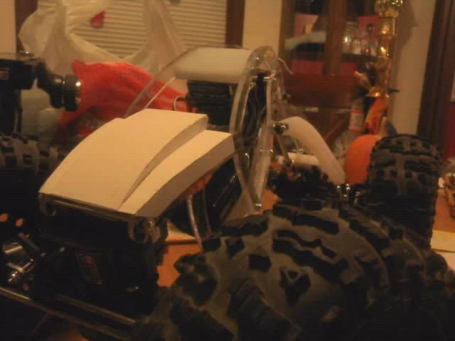 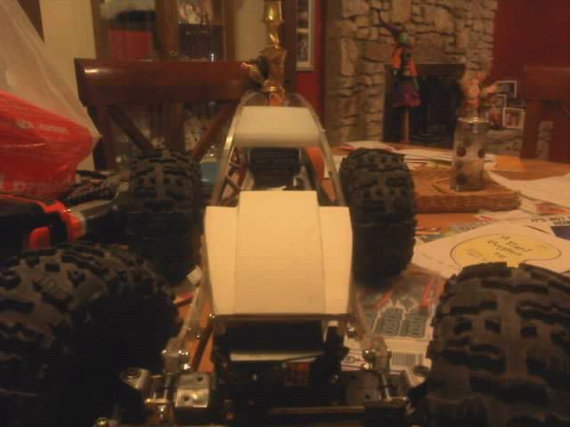  Here's a picture of the hood from the underside. You can see all of the little glue tabs that holds it all together. 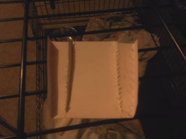 |
|
| |
|
10-27-2011, 09:19 AM
| #20 |
| Quarry Creeper Join Date: Aug 2005 Location: Jefferson City
Posts: 345
|
OK, here's a little update, sans pics or vids. Finally got the spur gear in yesterday. Well, let's just say that I have quite a gap between the spur and my pinion. I didn't realize that the spur was going to be SO DAMNED SMALL!! I now have to figure out how to add an idler gear to the mix. I'm going to try and mount an idler gear using one of the motor's unused mounting holes. I have a couple of other ideas, but I need to take the tranny/motor out so I can mess around with the idler positioning. I was able to get one coat of polyester resin on each side of the hood. I think I'm going to stop there, as it's just flexible enough (like lexan) but not too rigid that it's going to crack and break when I roll over. It definitely doesn't feel like cardstock anymore, either. If anyone has any links showing different homemade transmissions, GRUs or transfer cases, send 'em my way. Wanting to look at different ways of adding the idler gear. |
|
| |
 |
| Thread Tools | |
| Display Modes | |
| |


 Linear Mode


