| |
 12-25-2005, 05:09 PM
| #61 |
| Newbie Join Date: Jul 2005 Location: Norway
Posts: 14
|
i have been using Solid Edge and EdgeCam fore about 2 years now... great pgms.. |

|  |
| Sponsored Links | |
| | |
|
12-25-2005, 06:04 PM
| #62 |
| I wanna be Dave Join Date: Jun 2004 Location: Centennial, CO
Posts: 2,129
|
Autocad/solidworks would recquire some learning, however, I'm sure you could figure most of it out on your own. Most programs are very similar. I taught myself mastercam with the very basic book they include to get you started. And this was still in highschool, within three months of starting I had to make my first part for my senior project. Also, there are CAD/CAM forums forums you could easily hop on and get help with, instead of ponying up the cash for the books/classes. (the class for solidworks is something like $900) |
|
| |
|
12-25-2005, 08:09 PM
| #63 |
| Rock Crawler Join Date: Dec 2004 Location: Land of the Free, because of the Brave
Posts: 891
| Thanks for the advice PWT. The thing is, my company will pay for any drafting/machining related classes. All I have to do is pass... -WRM |
|
| |
|
12-29-2005, 03:09 PM
| #64 | |
| Quarry Creeper Join Date: Jan 2004 Location: CSU, CO
Posts: 290
| Quote:
 | |
|
| |
|
12-29-2005, 03:47 PM
| #65 | |
| RCC Addict Join Date: Aug 2005 Location: Akron
Posts: 1,784
| Quote:
| |
|
| |
|
12-29-2005, 03:49 PM
| #66 |
| Rock Crawler Join Date: Nov 2005 Location: Oak Ridge
Posts: 590
|
This is the extent of my CAD ability...  |
|
| |
|
01-01-2006, 05:22 PM
| #67 |
| RCC Addict Join Date: Aug 2005 Location: Akron
Posts: 1,784
|
Cubman, further than most people! I had a chance to play around with cinema a little more since we were slow at work. Decided to update the rendering of my crawler. 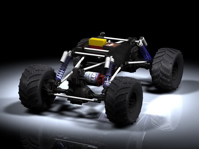 |
|
| |
|
01-02-2006, 12:26 AM
| #68 |
| Rock Stacker Join Date: Aug 2005 Location: Hiding in a Cornfield
Posts: 65
|
WOW |
|
| |
|
01-24-2006, 06:21 AM
| #69 |
| RCC Addict Join Date: Aug 2005 Location: Akron
Posts: 1,784
|
hey guys, didn't want to bring back an old thread but I didnt' want to start a new one either. The place I work for has aked me if I would like to upgrade the software we are using. So I need to do some research. We are currently running AutoCAD R14 (yes I know.... really old) Everything we do however is 3D so I'm really wanting to get something that will be oriented around 3D. I'm not sure what they want to spend so I think I need to give them some broad options. One option is to obviously upgrade to a new CAD version but since you all have experience with some newer programs I thought I would get some opinions. Let me know what you all think and if there is a good site out there for comparing let me know. I think 3 we are looking into now are autoCAD 2005, solidworks and inventor.
|
|
| |
|
01-24-2006, 08:00 AM
| #70 |
| I wanna be Dave Join Date: Jun 2004 Location: Centennial, CO
Posts: 2,129
|
What kind of things do you need to design? Some programs have stress test diagnostics built in and some don't. If that's some thing that interests you. ProE or Solidworks would be my choices, but I don't know their pricing. |
|
| |
|
01-24-2006, 08:31 AM
| #71 |
| RCC Addict Join Date: Aug 2005 Location: Akron
Posts: 1,784
|
Well we do displays so there really doesn't need to be stress diagnostics. I'd say at most maybe something that would alert for parts interfering? Basically CAD worked great for it but was starting to lack in some areas. Try making a spring in R14.... I managed to but talk about a pain. Basically looking for something to dimplify drawing and handle more complex models but also can be used for detailing. |
|
| |
|
01-24-2006, 08:42 AM
| #72 |
| Newbie Join Date: Nov 2005 Location: Perry
Posts: 24
|
SolidWorks has a built in interference detection program that works pretty good. I personally would go with SolidWorks or Pro E or some program along those lines. Autocad is great for 2d stuff but sucks the big one when it comes to 3d compared to some of the other programs out there. You said that it took you a while to create a spring in autocad? I can create a spring in solidworks in less than a minute, with only two sketches, one helix, and one circle for wire dia. Then just sweep the second sketch only the helix instant spring.
|
|
| |
|
01-24-2006, 08:47 AM
| #73 | |
| RCC Addict Join Date: Aug 2005 Location: Akron
Posts: 1,784
| Quote:
For me to draw a helix I had to use a list routine for cad that basically has you put the input in to make the 3d spiral. Then it calculates your input and links small straight lines into the shape of a 3d spiral allowing you to extrude a circle along their path to make the 3d spiral. Not only does it look weird (since it's a lot of lines) it makes for a nice size file. I can make them REALLY fast now (probably 20 seconds) but they aren't real 3d spirals and aren't efficient at all. | |
|
| |
|
01-24-2006, 07:57 PM
| #74 |
| Pebble Pounder Join Date: Jan 2005 Location: st. louis
Posts: 115
|
autocad is a pain to make a 3d spring in. for 2d, dont get much easier than autocad. for 3d, out of the box ease of picking up and making stuff I would say inventor. the tutorials built in are real nice. and from what the sales guy told me it imports in autocad files just fine. second would be solidworks, currently self teaching my way through it. its ok, dont like how the assembly part of it works. just a flat out pain. have yet to get into the rest of it... stress stuff, flow works, etc.. right now I'm using surfcam for NC programs, getting a trial copy of mastercam to see if I like it better. the best all in one program I have used was Unigraphics. you could do it all, 2d/3d, assemblies, NC program, sheetmetal/flat pattern, drawings all in one nice neat package. you buy a REAL nice car for what it cost though. solidedge is their poor mans version, never used it though. Last edited by BUBBA069; 01-24-2006 at 08:07 PM. |
|
| |
|
01-24-2006, 08:29 PM
| #75 |
| Newbie Join Date: Feb 2005 Location: Milwaukee
Posts: 26
|
NIck, I would say that Inventor would be the best for your needs.
|
|
| |
|
01-24-2006, 08:56 PM
| #76 |
| I wanna be Dave Join Date: Jun 2004 Location: Centennial, CO
Posts: 2,129
|
Assemblies are tough. Make sure you are doing combining the components in a certain order. Once a component is constrained, if you try to add another piece in the wrong order, it will try to move the piece that is fully constrained and an error will occur. I actually found the assemblies in solidworks 10x easier than inventor's. Inventor would get the job done. I guess it comes down to money spent. I feel solidworks is a much more powerful tool than inventor, and while I have not used ProE, it looks as top notch as solidworks. I saw TurboCAD for $22 at officemax. |
|
| |
|
01-25-2006, 06:45 AM
| #77 |
| Pebble Pounder Join Date: Jan 2005 Location: st. louis
Posts: 115
|
LOL turbocad... for the assemblies part of solidworks I want to have an assembly that has a key part locked to a certain point in space (o,o,o) as a master point. for some reason I cant get the flippin thing to show the planes to assoiate the base part to it. one other question, where can you change the display colors? I can't stand that blue background. |
|
| |
|
01-25-2006, 08:45 AM
| #78 |
| I wanna be Dave Join Date: Jun 2004 Location: Centennial, CO
Posts: 2,129
|
Its in the same menu you use to change units. There are multiple options on the left, one of them is visualization or something, and you can change the background color there.
|
|
| |
|
01-27-2006, 12:08 AM
| #79 |
| Rock Crawler Join Date: Mar 2004 Location: BAY AREA
Posts: 557
|
been working on shapes for my axles that I wanna produce.. I am getting closer and now I need to design how it will split and hold the diff.. Kinda the hard part I know..    |
|
| |
|
01-27-2006, 08:05 AM
| #80 |
| RCC Addict Join Date: Aug 2005 Location: Akron
Posts: 1,784
|
Doesn't look to hard to split. Bearing carriers are the tricky part. you should run a track around the outside with a gasket to seal them What are you doing for shock/servo/link/steering knuckle mounts? |
|
| |
 |
| |


 Linear Mode


