| |
 11-28-2005, 10:01 PM
| #1 |
| RCC Addict Join Date: Aug 2005 Location: Akron
Posts: 1,784
|
So there have been a few people on the site working with 3d programs and I thought I would start up a thread were we could all share some info. Maybe even share files that we have drawn. Explain how things were designed and what not. I know there were a few guys talking about animations. I just started messing around with the animations/rendering in cinema 4d tonight and thought I would make a couple quick 90 frame clips. I'll go ahead and post a few of the 3d models I have and the video clips. Click to enlarge photos. Heres a few shots of articulation I was messing with on a cut up nylint.   Scale nylint 1:6 with clod axles mocked up under for giggles.  Stock clod axle.  Clod axle with servo mount and behind the axle steering  Cinema allows you to apply materials to any object. These can be tiff images or jpg. Which is how I got the image on the motor in the stock axle rendering. Here are the video clips. Let me know if you have any and all questions. I'd really be interested in getting some files from people and would be more than happy to share the ones I have. http://media.putfile.com/4-wheel-steering http://media.putfile.com/Rendered-articulation |

|  |
| Sponsored Links | |
| | |
|
11-29-2005, 12:33 AM
| #2 |
| Rock Crawler Join Date: Mar 2004 Location: BAY AREA
Posts: 557
|
Very cool Nick... the animations are trick... I want to get the links to be the positioning anchor so I could see it cycle.. but I am lost.. anyways heres a few I have worked on.. Mad force axles, emaxx tranny, and narrowed jumb kongs...    After a veiw of lukedogs thread of his maxx axle build, I was left with a different though.. I liked the tubes he used as the housing. Kinda like the new ATOMIC axle from Overkill engineering....   Playing with it more using savage shocks set at half stroke.. same emaxx tranny and U design chassis....   have a few more, but nothing related to crawlers... I thought I could get the most out of spending the time to design on CAD and build knowing that it would fit (as long as its to scale, so I spent the extra time) but the real world is a lot different.. |
|
| |
|
11-29-2005, 06:28 AM
| #3 |
| RCC Addict Join Date: Aug 2005 Location: Akron
Posts: 1,784
|
Awesome work skipstr. Very nice. Have you ever messed with Inventor? Amazing program. You can set limits for objects to rotate on axis' or plains. So that they only move according to the limits set. example would be making an axle move like in my animation, but assigning the endpoint of a 4-link bar to stay attached to a point on the axle the whole time. Then also assigning the opposite side of that link to the chassis. Then when animated the link will follow the real travel of the axle. It's very awesome. I have only messed with it a few times but have a friend thats pretty fluent in it. Can you export any of those drawings into .3ds? I'd love to mess around with the axles, revo shafts and tranny. I'm trying to get this animation stuff down but its tricky. Also, do you think that u-frame will flex where the upper portion of the shock mounts since there is no cross member between the top halves of the frame? I was getting a little frustrated myself with the animation in cinema. I couldn't find an easy way to find the centers of objects. I had to place the coordinate system manually for everything so that it would know where to rotate. It took a while.... then I couldn't find out how to make clips longer than 90 frames. Those two clips are 90 frames and took 30 minutes to render each. Thats without fancy materials and only 2 lights on the truck. Last edited by NickRummy; 11-29-2005 at 06:33 AM. |
|
| |
|
11-29-2005, 08:33 AM
| #4 |
| Rock Crawler Join Date: Mar 2004 Location: BAY AREA
Posts: 557
|
Nick.. Thanks man. I never thought that I would have the correct place to share them. I hope that the files we have can be shared, bacasuse I can learn alot from looking into your asembly. I know I can export a file that you can import. I say that because, as old as this software is, we still use it at work to comunicate via 3D solid models at work. Its just a matter of the correct file to send you.. I can do .3ds... The animation feature is the real help when designing a complete rig on 3D.. I dont see the need to go much further if I cant cycle the suspention and look for binds or contact points.. I'm hoping you can show me a trick or two.. When I ask my boss how to do it, he is stumped.. and thats my only other relationship with another 3D solid modeler untill now.. Not to long ago we watched the guys from Solidworks do a demo, and they had a copy machine "print" out a page and you could look at every gear, servo, motor move/turn... It was very impressive as simple as it really was for the software... The U chassi I stated is really not finished. That represenst the bottom of the chassis I am working on. After the plastic is formed over the bottom of it, there would be no edges to catch on. Nice and slick..! the upper half changes with the sytle of "tuber" I am drawing/building.. I had it completed and looking good, when the comp crashed.. even though I had Ctrl-S, it was lost.. I have since saved after evey move.. Thats the one main issue with this software, and the bigger the file, the worse it gets.. I will share any of my files if you wanna.. I'd be happy to look and see how you got there.. Like I said, cool thread.! |
|
| |
|
11-29-2005, 08:41 AM
| #5 |
| RCC Addict Join Date: Aug 2005 Location: Akron
Posts: 1,784
|
Sounds like a plan! I'm using good old CAD version R14 for the solid modeling. So if you can save anything as an R14 .dxf that would be the prefered method. That way i can open it in cad. If you can't save it as that then I can take a .3ds What would be a good file for me to send to you? Usually dxf is pretty standard in 3d modeling. I'm not sure how much you will learn from me. I haven't really been doing it that long. I did a lot of 2d floor plan work. Started 3d for fun basically and now I design and detail product displays and do them in 3D so customers can see full views. Email me at nrumschlag@point-of-sale.com if you would like to exchange some files. I have a few at work to send and can send some more when i get home. |
|
| |
|
11-29-2005, 11:05 AM
| #6 |
| Newbie Join Date: Feb 2005 Location: Milwaukee
Posts: 26
|
Anyone else in here use Pro-E? I am a current user and also use other programs such as AutoCAD, Solid Works, and I use WorkNC for my CAM software.
|
|
| |
|
11-29-2005, 11:34 AM
| #7 |
| RCC Addict Join Date: Aug 2005 Location: Akron
Posts: 1,784
|
Pro-E? I wish! haha that cam stuff really interests me but don't know anyone who uses it. My dad is a machinest for parker hanifin. They have some cool cnc machines there. unfortunately hes not trained on one. I'd love to know some details on that stuff. |
|
| |
|
11-29-2005, 02:42 PM
| #8 |
| Newbie Join Date: Nov 2005 Location: Perry
Posts: 24
|
After seeing all the tube rigs I have been inspired to design and build one. I've never used the programs you guys are talking about other than some old autocad. The only 3d software that I use is Solidworks. I work in the R&D department for a company that makes exercise equipment all I do all day is design injection molded plastic parts in soldworks. I started modeling a tube chassis today I'm just playing around with some ideas when I have a design that i like I'll post some pics. Nickrummy is there anyway you could send me a 3d file of that clod axle you modeled? that would work sweet in my setup then I wouldn't have to model one for myself. guess I should mention that I have 6 years of solidworks modeling experiance |
|
| |
|
11-29-2005, 03:33 PM
| #9 |
| RCC Addict Join Date: Aug 2005 Location: Akron
Posts: 1,784
|
trplxj, i just sent you a pm. I was confused and thought you posted in the other thread haha anyways. I'd be more than happy to send that clod axle file to you. let me know what your email is. It is not PERFECT though. Really close. I dimensioned each individual piece then put it together to see how close it would be. Off about .06 on the overall width. the diff halves are a little off on some dimensions. its hard to dimension them accurately. |
|
| |
|
11-29-2005, 05:45 PM
| #10 |
| Rock Crawler Join Date: Mar 2004 Location: BAY AREA
Posts: 557
|
trplxj.. I would think that the complexity of injection molded parts is alot tougher than the design of a tube chassi and axles.. From your years of experience you should have some great stuff to bring here.. Looking forward to it.. I too wish I had Pro E... I am looking for a good Solid works program that i can download off the net.. Thats what 99% of the companys I know are using.. Nick.. R14 is the best for me too.. I can do .3ds like I said also.. I will send a file over and you can LMK if you can work with it.. I think tonight I may go back to the Jugg axles and servo mounts I was working on a few months back.. |
|
| |
|
11-29-2005, 09:42 PM
| #11 |
| Newbie Join Date: Nov 2005 Location: Perry
Posts: 24
|
yea designing plastic parts can be pretty hard at times. I could easily sit down and model the axles but he has them done already I still may model them myself. I hardest part in designing the chassis for me is getting it to look good. I've seen some that look just freaking awesome and some that don't look so good. I'm also into wheeling the full size guys too. Some friends of mine have built a couple comp buggies and they work really well. My main goal is to design a scaled down version so I want to get all the link lengths and positions correct. I understand that it's not as big of a deal with the rc buggies as it is with the 1:1's. I spent my lunch hour and did a almost complete chassis, but it wasn't quit what I wanted. I'll keep playing with it. When I get to work tomorrow I'll post a jpg of the chassis.
|
|
| |
|
11-29-2005, 11:00 PM
| #12 |
| Rock Crawler Join Date: Mar 2004 Location: BAY AREA
Posts: 557
|
Looking forward to seeing some stuff... I too would use his axle if I had clod axles in a project..! Thats very clean and he got every mold detail in there.. Now this isnt a complex drawing.. actually i didnt spend time with the "look" of it what so ever.. The design of this rim can be changed without interfearing with the functions of the bead lock. So its a 3 peice design bead lock.. As I have the 4 peice maxximizers, these are the same concept.. Clamping the beads using a center floating unit.. So there is only the screws on one side. Making removal quick, and weight down low.. If I were to have them machined they would be made of Delrin, or some type of quality plastic.. Narrowed offset maxx size beadlocks... (same concpet for 2.2's)    The main thing with these is to get the clamp gap right.. but as I see it, it should work.. what do ya think...? ... |
|
| |
|
11-30-2005, 06:12 AM
| #13 |
| RCC Addict Join Date: Aug 2005 Location: Akron
Posts: 1,784
|
I like! I have been dying to design up some 2.2 beadlock wheels but I don't have any wheels in my posession to take dimensions from. Looks like the same concept as the associated wheels only the screws are on the outside ring of the rim instead of the center. I think it should work pretty well. Can you do a quick cut away of the assembled rim? Just chop it down the center to show how it all settles together. |
|
| |
|
11-30-2005, 09:04 AM
| #14 |
| Quarry Creeper Join Date: Jan 2004 Location: CSU, CO
Posts: 290
|
skipstr71 amazing model! I skimmed the thread and didnt find what program you are using to model your parts, can you post what program you are using. Also is the ring and pinion you made a true bevel gears? I ask because I had a hell of a time drawing this:  If they are true bevel gears could you please elaborate on how you drew the tooth profile? |
|
| |
|
11-30-2005, 09:08 AM
| #15 |
| RCC Addict Join Date: Aug 2005 Location: Akron
Posts: 1,784
|
Just messed around with it real quick and figured this would be easiest in CAD. Just draw the top tooth profile from the side with the right angle then array it around the center of the gear. Seems to the be the easiest? Of course fill in the rest of the gear accordingly. I think i have one at home i'll try and draw tonight. I never have before. Last edited by NickRummy; 11-30-2005 at 09:22 AM. |
|
| |
|
11-30-2005, 09:20 AM
| #16 | |
| Quarry Creeper Join Date: Jan 2004 Location: CSU, CO
Posts: 290
| Quote:
 Sorry for the poor quality and huge file size, I am at school and MS paint wont let me save as a jpeg. | |
|
| |
|
11-30-2005, 09:26 AM
| #17 |
| RCC Addict Join Date: Aug 2005 Location: Akron
Posts: 1,784
|
looks good to me. I don't have a gear sitting in front of me to say for sure. Thats how I would try it though. Did you make the gear without teeth first then creat the profile to use to subtract from the gear to make the teeth? Some programs have gear modeling built in. Determing pitch, teeth count etc. . . |
|
| |
|
11-30-2005, 12:30 PM
| #18 |
| Newbie Join Date: Nov 2005 Location: Perry
Posts: 24
| Here's the progress on my chassis so far. I still need to finish the cab and hood area and add some shock hoops, shocks, links and link mounts. 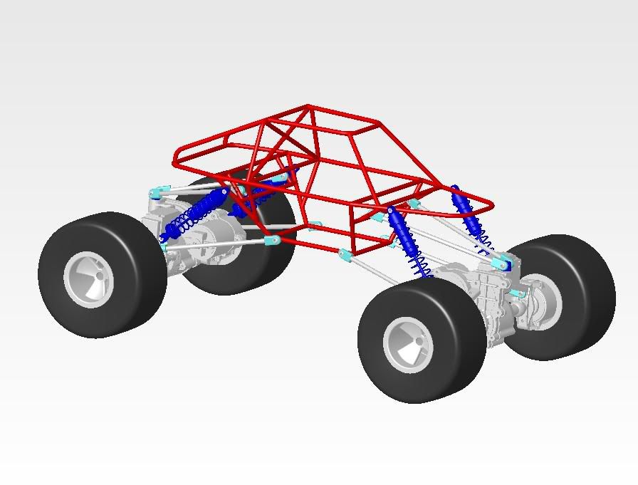 |
|
| |
|
11-30-2005, 01:37 PM
| #19 |
| RCC Addict Join Date: Aug 2005 Location: Akron
Posts: 1,784
|
NICE! Any straight on side shots? Are you leaving it an exposed tuber or do you plan on running a lexan body over it? |
|
| |
|
11-30-2005, 02:02 PM
| #20 | |
| Newbie Join Date: Nov 2005 Location: Perry
Posts: 24
| Quote:
| |
|
| |
 |
| |


 Linear Mode


