| |
| |||||||
 |
| | LinkBack | Thread Tools | Display Modes |
 02-05-2007, 08:27 PM
| #1 |
| Pebble Pounder  Join Date: Mar 2006 Location: Crow Head
Posts: 143
|
I will try and do a step by step build up of my Maxx but I sometime tend to get a little carried away and forget to take enough pictures. For this build I decided to build my own axles. I started by cutting 1/4" rod at 6 1/2" in length. Next I squared one end on the grinder. Set your tool rest at 90 degrees to the wheel and spin the rod till it gives you a flat surface. You don't need to apply to much pressure just a couple quick twists will do it.  Next clamp them in a drill press vise and then square it to the drill bit. I was lazy and did all of them by eye but a cheap plastic square will work. I bolted the vise to the table and made sure the rod was bearing down on the table to prevent the drill press from pushing the bit down through the vise. I use a hammer to knock the vice a little to fine tune my setup. Make sure to use a good drill/tapping lube.  Once drilled tap the end with a 5 mm x .080 tap. Make sure it is deep enough to install the ball end all the way. You will want to use a 5 mm nut to lock the ball end but I always make sure that I can run the ball end in all the way anyway.  Test the ball end to ensure a good fit.  Last edited by sfrankland; 04-08-2007 at 06:16 PM. |

|  |
| Sponsored Links | |
| | |
|
02-05-2007, 08:39 PM
| #2 |
| Pebble Pounder Join Date: Mar 2006 Location: Crow Head
Posts: 143
|
Next I drilled my washers on my drill press with a 1/4" drill bit and then ran a 1/4" bolt down through the hole to hold all the washers together while I drilled the second hole. Next I took a drill with a 1/4" bit and elongated the hole so that it would allow the 1/4" rods to be set on an angle to the washer. Use a ruler to set the length and  an angle gage to set the angle.  By drilling the washers and cutting the rods a little longer than what I needed I was able to clamp the extra on the ends into a vise.  By installing your knuckle the other rod is automatic set to the right angle and offset. I brazed my rods and the heat had no affect on the plastic knuckle.  |
|
| |
|
02-05-2007, 08:53 PM
| #3 |
| Pebble Pounder Join Date: Mar 2006 Location: Crow Head
Posts: 143
|
I mocked up what I had to get an idea of how big the rig was going to be and to start planning my tube chassis.  The axles are going to be bolted together with 1/4" brake tube cut to 1" lengths to be used as spacers. I spaced the holes on the front of the axle far enough apart that I can rotate the diff up wards to give me a better drive angle. Over all the the width is 17", I was looking for 16" - 16 1/2" but 17" will do. A have about 3 1/4" clearance under the diff.  Started the tube work and as I stated above I got a little carried away and never took may pics of the tube work while in progress. The wheel base is 17" and the over all length will be 20" - 22". I also have about 3 3/4" clearance under the chassis. This is by no means going to be a comp truck.  All that is needed to finish the chassis is the battery tray and the link and shock mounts.   |
|
| |
|
02-05-2007, 09:26 PM
| #4 |
| Quarry Creeper Join Date: Oct 2005 Location: Bryant, AR
Posts: 463
|
That looks pretty good. I know you said you are using brake tubing to space the axles, but I found something that is alot easier to get on and off to space axles. They are Thunder Tiger .30 Heli frame nuts. Instead of having a screw going through with a nut on one end, I can use 2 3mm screws, one at each end. It is easier, because you don't have to try to hold the nut from spinning while trying to get the other end with a screw driver. You can just grip the spacer I find it alot easier. The part number is TTRPV0057 Here is a link to some. If your hobby shop does helis, you can probably get them there. http://www.onlyraptors.com/new_morei...3e5120b2c9b953 You can see mine in this pic, I also used some 3mm washers because the frame nuts are slightly shorter than the width needed. 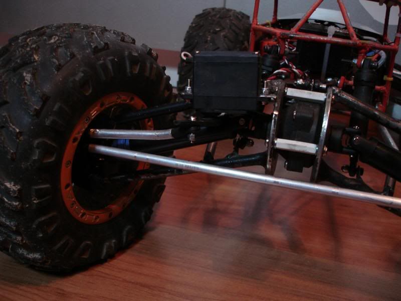 |
|
| |
|
02-05-2007, 09:28 PM
| #5 |
| RCC Addict Join Date: Jun 2004 Location: Bruiser Heaven!!!!
Posts: 1,463
|
looks awsome and i really like those kind of axles on a maxx crawler. and keep up the good work too. rich |
|
| |
|
02-05-2007, 09:46 PM
| #6 |
| Pebble Pounder Join Date: Mar 2006 Location: Crow Head
Posts: 143
|
TNXONR I was thinking about using threaded rod joiners cut to length because of the cleaner look but the heli spacers would be better as I always have a good supply of RC nuts and bolts on hand. Maybe worth ordering. By the way my nearest hobby store of any type is over a 1000 miles away. :-( I am still looking at how to mount my servo. My options so far are on the axle, on the center diff or if I build a three link setup then place it on the link plate. Rocpede those axles are the reason I build a maxx crawler. I think they look sick myself. I am not sure if I am going to add any more bracing to them as they are very stiff as is. |
|
| |
|
02-06-2007, 06:06 AM
| #7 |
| Colt Python/SR9c  Join Date: Feb 2004 Location: out in the shop, reloading ammo!
Posts: 8,626
|
I highly suggest adding braces. The force applied will bend them. On the spacers, Sears hardware sells some Alum spacers that are 1" also. If I recall correctly, they are set for 6-32" screws. One thing I wanted to add, is that the 5mm tap is 5mmx.080 tap. Since they make different pitch threads, the .80 is the one you need to work with the pillow balls. As for your servo, that is why I started making the sideplates. That way you can mount the servo up on top. Looks good so far  BTW- I just added this thread to the top sticky, under axles  Last edited by TwistedCreations; 02-06-2007 at 06:10 AM. |
|
| |
|
02-06-2007, 06:39 AM
| #8 | |
| Quarry Creeper Join Date: Oct 2005 Location: Bryant, AR
Posts: 463
| Quote:
| |
|
| |
|
02-06-2007, 07:11 AM
| #9 |
| Colt Python/SR9c Join Date: Feb 2004 Location: out in the shop, reloading ammo!
Posts: 8,626
|
I personally think any form of these axles should be braced..I built some from 5/16" also and thought the same, came off a drop off and landed hard on a wheel and bent the axles.. It all depends on your driving style.. I have always driven it, like I stole it though |
|
| |
|
02-06-2007, 07:35 AM
| #10 |
| Pebble Pounder Join Date: Mar 2006 Location: Crow Head
Posts: 143
|
Wow I have never been stickied before. I guess I will have to finish this with a few more pics. I noticed a bit of flex in my axles so I worked on my link setup and I have decided to brace the axles for strength and the mounting point for the links. Also figured I would add some sort of hoop to the front for looks and for sliding over rocks. |
|
| |
|
02-06-2007, 08:54 AM
| #11 |
| Pebble Pounder Join Date: Mar 2006 Location: Crow Head
Posts: 143
|
Laid out the brace and marked the rough angle and cut it with the hack saw. Then used a file to get it fine tuned to leave a nice tight fit. By cutting it in the middle you can get two braces for the price of one.  The other end was trimmed to give me the length I wanted and the length and fit was fined tuned with a file. Once done just need to cut 7 more like it.  A rare earth magnet was used to hold the rod ends to the washer will I test fit and brazed the braces to the main axle rods.  Complete axle time to braze it all together. The magnets do a awesome job in keeping everything in line while brazing.  The first one done 3 more to go. Need to get some more 1/4" rod to finish up the axles.  |
|
| |
|
02-06-2007, 08:56 AM
| #12 |
| Pebble Pounder Join Date: Mar 2006 Location: Crow Head
Posts: 143
|
I really need to clean my bench it was getting hard to find a clean place to work. |
|
| |
|
02-06-2007, 11:39 AM
| #13 |
| Colt Python/SR9c Join Date: Feb 2004 Location: out in the shop, reloading ammo!
Posts: 8,626
|
You could use 3/16" brakeline or even solid, to help save some weight.
|
|
| |
|
02-06-2007, 12:40 PM
| #14 |
| Pebble Pounder Join Date: Mar 2006 Location: Crow Head
Posts: 143
|
I didn't have anything smaller than 1/4" on hand but I figured that the extra weight down low will help with the over all COG. Since this is a basher I don't mind a little extra weight. The next Maxx I build will be a comp truck so I will go with the smaller stock. Keep the tips coming every bit helps. Scott Last edited by sfrankland; 02-07-2007 at 10:17 PM. |
|
| |
|
02-08-2007, 09:49 AM
| #15 |
| Pebble Pounder Join Date: Mar 2006 Location: Crow Head
Posts: 143
|
The finished axles. The servo mount will be a bracket that either mounts on top of the diff or on the axle tubes. Not sure as of yet but I am planning on using 1/4 scale servos as that is all I have on hand for now. If I like them I will keep them but I some how figure I will be swapping them out for smaller high torque servo.   |
|
| |
|
02-09-2007, 04:10 PM
| #16 |
| Rock Crawler   Join Date: Sep 2006 Location: Lititz
Posts: 787
|
I vote for on top of the axle,if you have the room. I think that servos, and batterys, sitting on the axle tubes looks stupid imo. nice detailed thread on the axles by the way |
|
| |
|
02-14-2007, 07:09 AM
| #17 |
| Pebble Pounder Join Date: Mar 2006 Location: Crow Head
Posts: 143
|
Have been toying with a few ideas on how to mount the servo but I have yet to build it yet, something for me to do to day I guess. Cannot find anything to build my links out of yet. The store in town does not stock threaded rod as small as I need it. Guess I will have to wait till next weekend when I head into the city.
|
|
| |
|
02-15-2007, 10:22 AM
| #18 |
| Pebble Pounder Join Date: Mar 2006 Location: Crow Head
Posts: 143
|
I cut 1/8" aluminum on the table saw to make the tray and side brackets. The table saw does a excellent job on aluminum. I am going to be mounting a 1/4 scale servo hence the big servo plate.  Clamped all four of the side brackets into a drill press vise and used it to drill all four mounting brackets at once. Since I drilled all the washers at once all the holes for the brackets are going to be the same.  Brazed the aluminum brackets onto the plate and bolted it all together for a test fit.  Still need to mount the servo post and the post for the links.  Last edited by sfrankland; 02-15-2007 at 10:30 AM. |
|
| |
|
02-15-2007, 11:01 AM
| #19 |
| I wanna be Dave  Join Date: Feb 2006 Location: Campbell, CA 4 hrs 2Rubicon !
Posts: 2,044
|
Really liking it !!! Great job Thanks for Posting your build |
|
| |
|
02-16-2007, 08:56 AM
| #20 |
| Pebble Pounder Join Date: Mar 2006 Location: Crow Head
Posts: 143
|
Finished up my servo mounts and my link mount and have the axles all put together hopefully for good this time all that is left is to connect the steering rods up and build the links. But first need to get some material to build the steering rods and links. I Installed 5mm lock nuts on the ball studs to lock them down. I first threaded them on the proper way and then took them off and threaded them on carefully backwards. By doing this it cuts a thread pattern in the nylon and helps to line it up when threading it on.  All the aluminum parts are brazed.   The servo sits just below the tops of the tires.   |
|
| |
|
| |


 Linear Mode


