So, to start out, yes, i know i misspelled bodyless  , but i can live with it so i hope you can too.:lmao:
Let me start out with a history on the F series chassis. I designed the F1 and ran it for a few months but wanted more angle on the skid, so came the F2. I lightened up the F2 a bit and so far am pleased with the performance of it.
Now to the important part, this is a rebuild of my current comp rig that I've been running a prototype chassis on , but since its the same geometry i'm not worried. Yes, i will be comping with this build rig.
The parts list:
Berg V1 axles with drilled and polished gears, also shimmed for less slop
Mann 2nd and 3rd gears
Clover Customs rear tubes
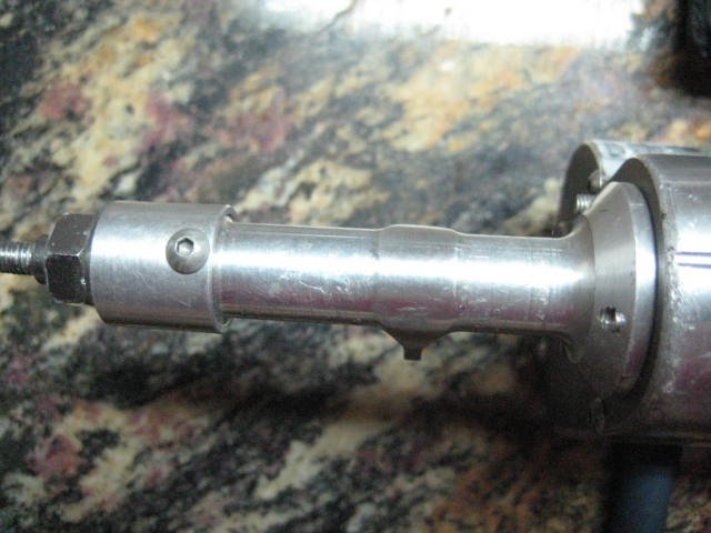
Axle Master rear axle
SDS super 300's for berg
RC Bros zero ackerman over sized bearing knuckles
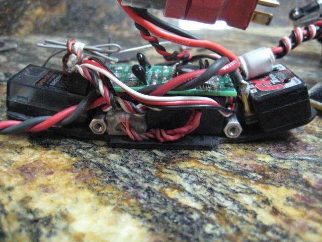
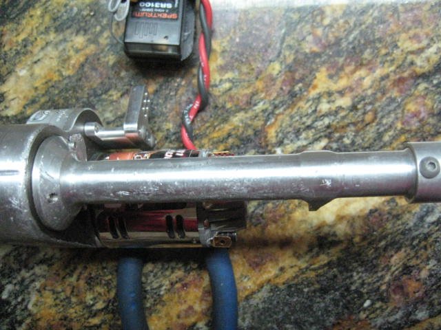
Tekin FXR ESC
Punk dig switch
Spectrum 3100 receiver
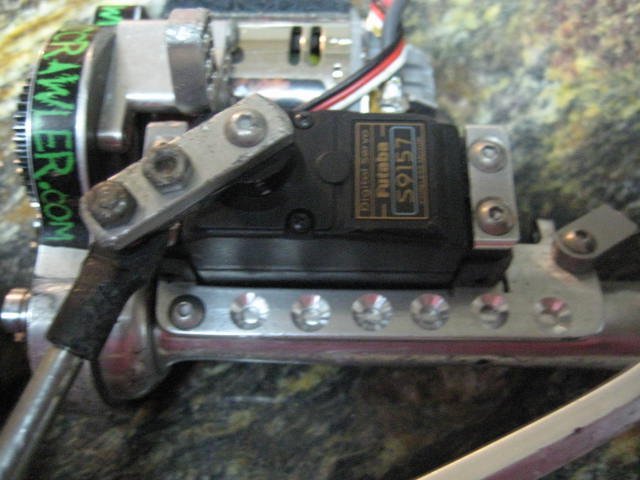
Futaba S9157 servo
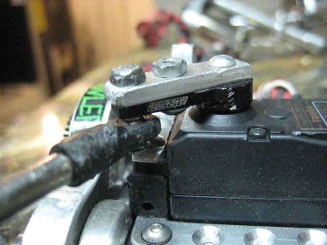
Racers Edge servo horn
16GA wire for motors
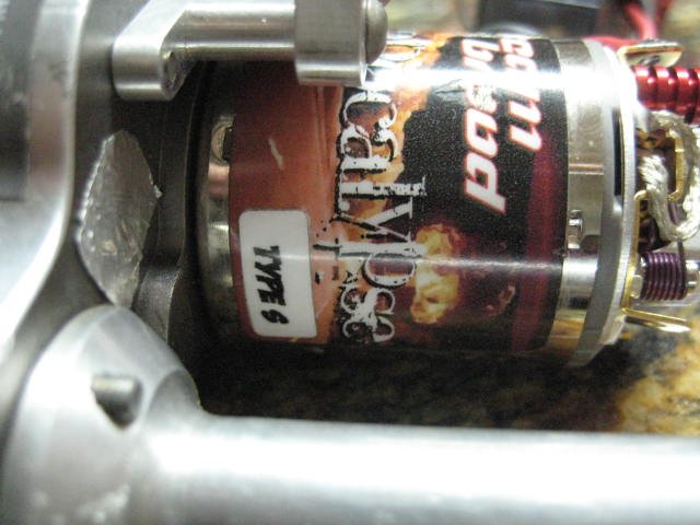
Brood Apocalypse Type S HHK epoxy balanced 35t motors
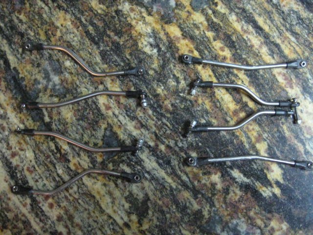
Lunsford Ti links upper and lower
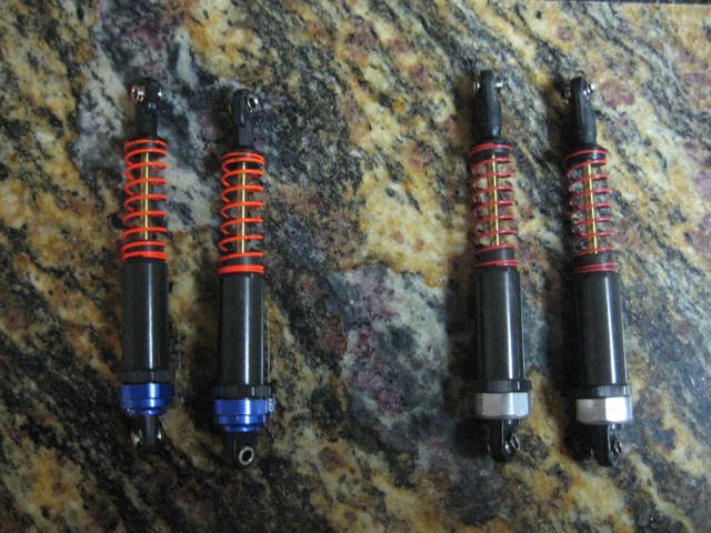
Big Bore shocks with Integy caps , Jeepin Doug mini-t spring cups, and mini-t springs, red up front and orange in back
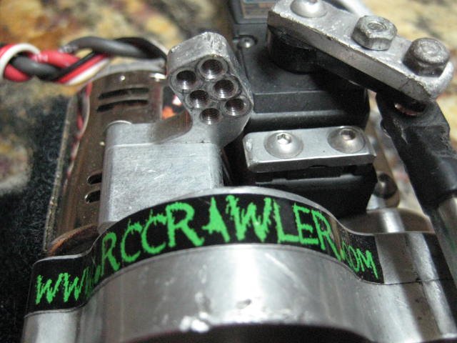
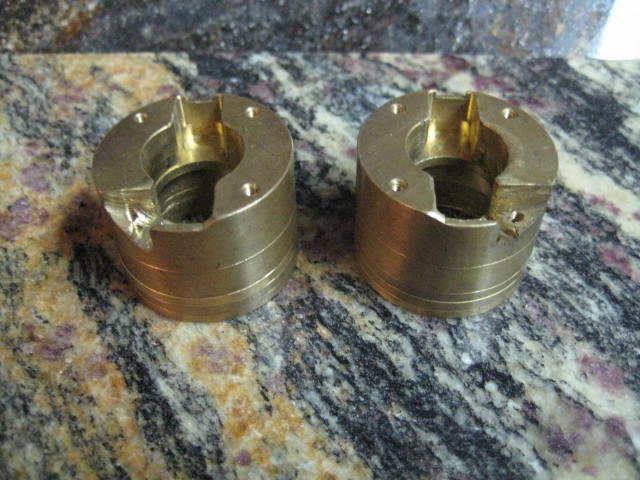
D-lux knuckle weights with 1 300 ring and 3 100 rings
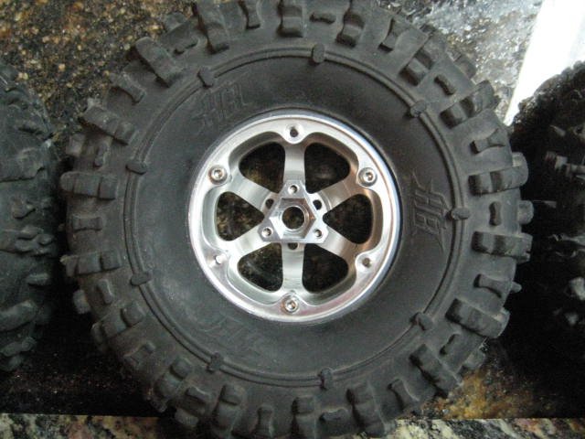
VP V2 1in. wheels in rear and V4's that were bent so i modded them to work again.
MFD custom triangle offsets
MFD berg 4 link mount
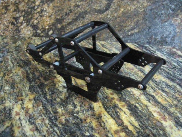
MFD F2 bodyless chassis
Aluminum and Ti hardware were ever i could use it.
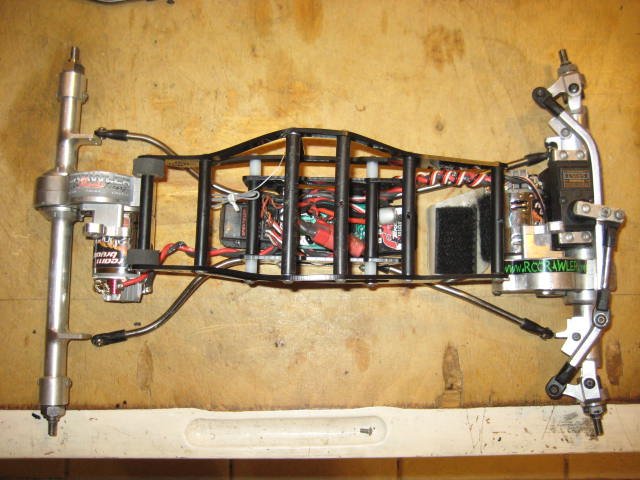
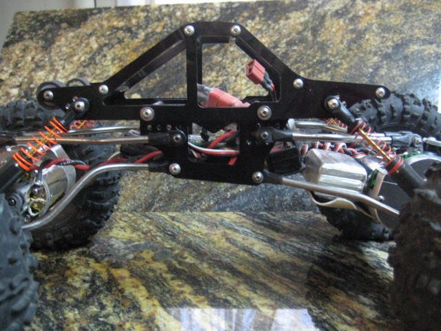
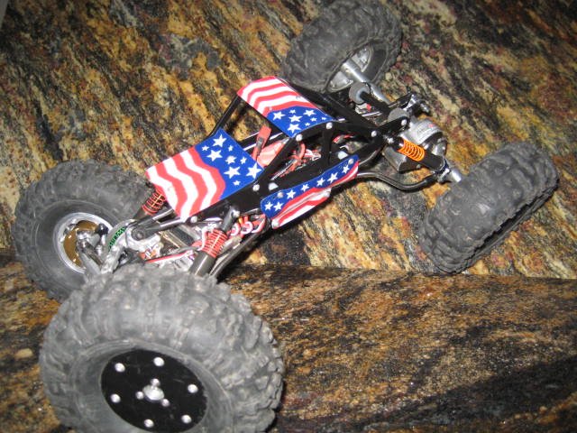
Now for some pics of this great list of products from some great vendors.
, but i can live with it so i hope you can too.:lmao:Let me start out with a history on the F series chassis. I designed the F1 and ran it for a few months but wanted more angle on the skid, so came the F2. I lightened up the F2 a bit and so far am pleased with the performance of it.
Now to the important part, this is a rebuild of my current comp rig that I've been running a prototype chassis on , but since its the same geometry i'm not worried. Yes, i will be comping with this build rig.
The parts list:
Berg V1 axles with drilled and polished gears, also shimmed for less slop
Mann 2nd and 3rd gears
Clover Customs rear tubes
Axle Master rear axle
SDS super 300's for berg
RC Bros zero ackerman over sized bearing knuckles
Tekin FXR ESC
Punk dig switch
Spectrum 3100 receiver
Futaba S9157 servo
Racers Edge servo horn
16GA wire for motors
Brood Apocalypse Type S HHK epoxy balanced 35t motors
Lunsford Ti links upper and lower
Big Bore shocks with Integy caps , Jeepin Doug mini-t spring cups, and mini-t springs, red up front and orange in back
D-lux knuckle weights with 1 300 ring and 3 100 rings
VP V2 1in. wheels in rear and V4's that were bent so i modded them to work again.
MFD custom triangle offsets
MFD berg 4 link mount
MFD F2 bodyless chassis
Aluminum and Ti hardware were ever i could use it.
Now for some pics of this great list of products from some great vendors.
Attachments
-
 IMG_2026.JPG96 KB · Views: 1,001
 -
 IMG_2005.JPG63.4 KB · Views: 1,082
 -
 IMG_2006.JPG68.1 KB · Views: 1,050
 -
 IMG_2004.JPG75.9 KB · Views: 1,025
 -
 IMG_2007.JPG56.2 KB · Views: 1,045
 -
 IMG_2013.JPG50.9 KB · Views: 1,011
 -
 IMG_2012.JPG56.1 KB · Views: 1,020
 -
 IMG_2011.JPG79.2 KB · Views: 1,014
 -
 IMG_2010.JPG88.1 KB · Views: 1,065
 -
 IMG_2008.JPG52.3 KB · Views: 1,035
 -
 IMG_2019.JPG62.5 KB · Views: 1,049
 -
 IMG_2017.JPG61.3 KB · Views: 1,000
 -
 IMG_2016.JPG51.2 KB · Views: 1,077
 -
 IMG_2015.JPG70.9 KB · Views: 1,051
 -
 IMG_2014.JPG60 KB · Views: 1,024
 -
 IMG_2020.JPG72.1 KB · Views: 1,031
 -
 IMG_2022.JPG86.7 KB · Views: 975
 -
 IMG_2028.JPG61.5 KB · Views: 1,031
 -
 IMG_2029.JPG70.3 KB · Views: 995