| |
 12-27-2008, 01:54 PM
| #1 |
| Pebble Pounder Join Date: Nov 2008 Location: Cincinnati, OH
Posts: 111
|
Thought I'd share some photos of the progress and modifications I've made so far with my truck. The goal, to try to make everything on it the best that I am capable of doing. Standard hop-up parts: --Novak Goat brushless speedo & 18.5 motor --Hot Bodies shocks --Axial slipper --DNA dig --Lunsford titanium screws here and there --SWX chassis kit --Aluminum straight/lock-out rear axles --Hot Bodies steel pivot balls to replace the stock plastic ones --MIP center driveshafts Planned hop-up parts (waiting for them) and modifications: --MIP "short/dig" length driveshafts to use F/R --aluminum spindles/knuckles & caster blocks --behind the axle steering with zero ackerman --4-link rear plate & 4-link front plate (including servo & battery mount one-piece) --HD gears f/r Look down for photos. Last edited by Jesse Robbers; 12-27-2008 at 03:10 PM. |

|  |
| Sponsored Links | |
| | |
|
12-27-2008, 02:06 PM
| #2 |
| Pebble Pounder Join Date: Nov 2008 Location: Cincinnati, OH
Posts: 111
|
Comparison shot of stock plastic ball on the left vs. HB metal ball (#A133 5.8mm x 6mm)on the right. The HB ball gives a little larger range of motion, will not bind under load, and you don't have to be afraid to tighten the screws too tight which might break or bind up the stock plastic balls. The HB steel ball is about .75mm narrower on the small side and about 1.25mm narrower on the flanged side from the stock plastic ball. So some thin shims are needed to fit it well and also allows to position the link in more positions then the stock plastic balls do. 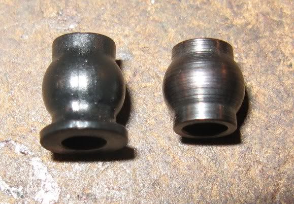 After shimming the stock diff gears side to side for a good gear mesh, the right rear axle was being pressed against the diff gear. This made the gear mesh too tight and caused binding. So I sanded the red area on the diff gear until I had a bit of end play on the axle to make it "right". The front axle did not need this and I am waiting for the HD gears to show up. 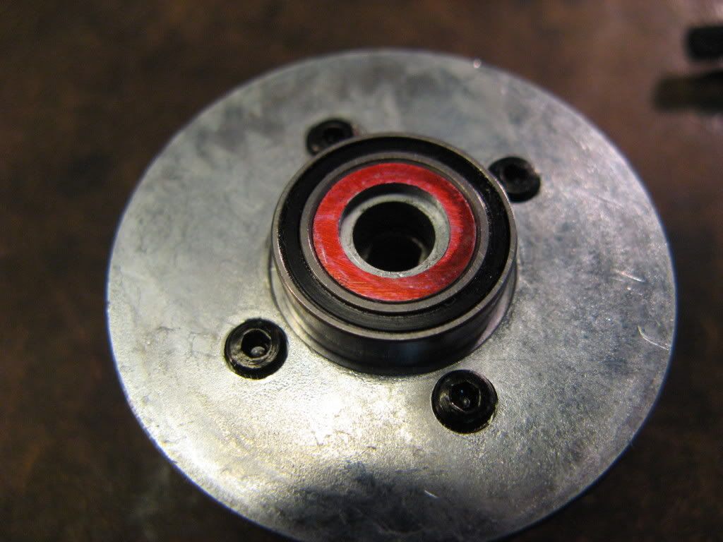 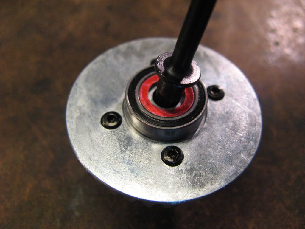 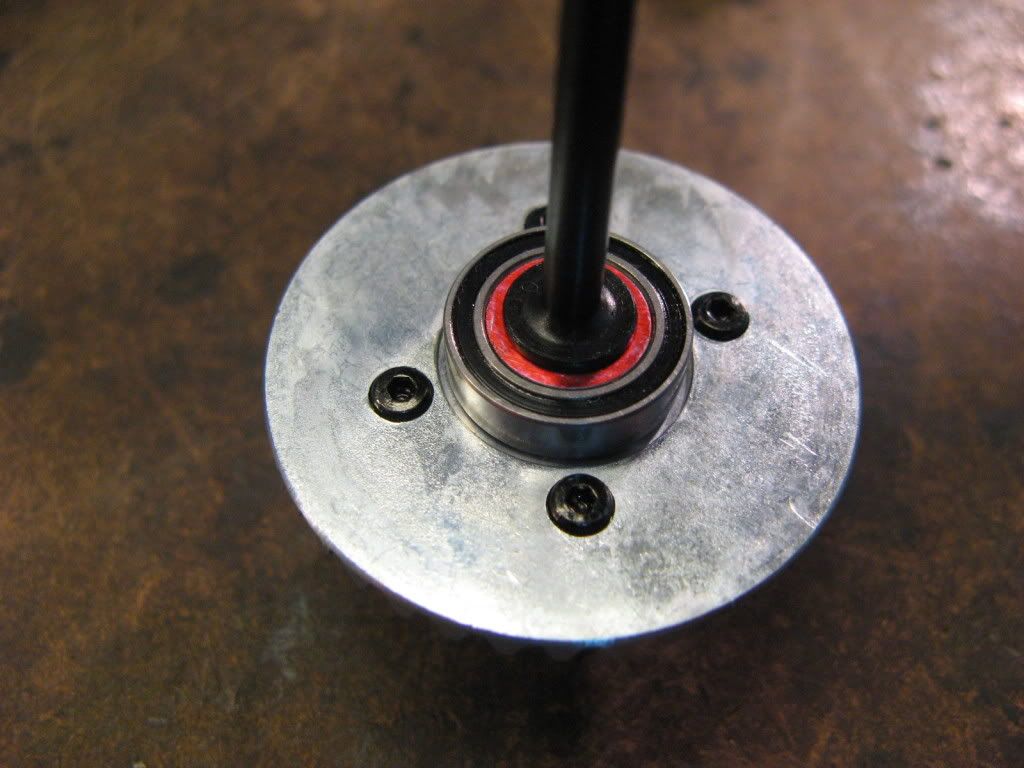 Had to dremel a chamfer into the chassis side plates to give clearance for the lower links f/r. 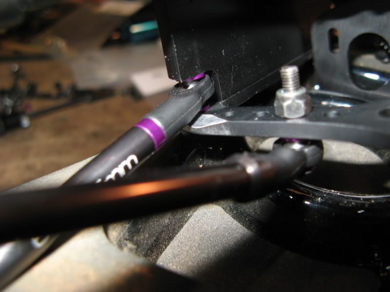 Installed a shim on the shocks to raise the lower spring cup to keep it from interfering with the lower links. 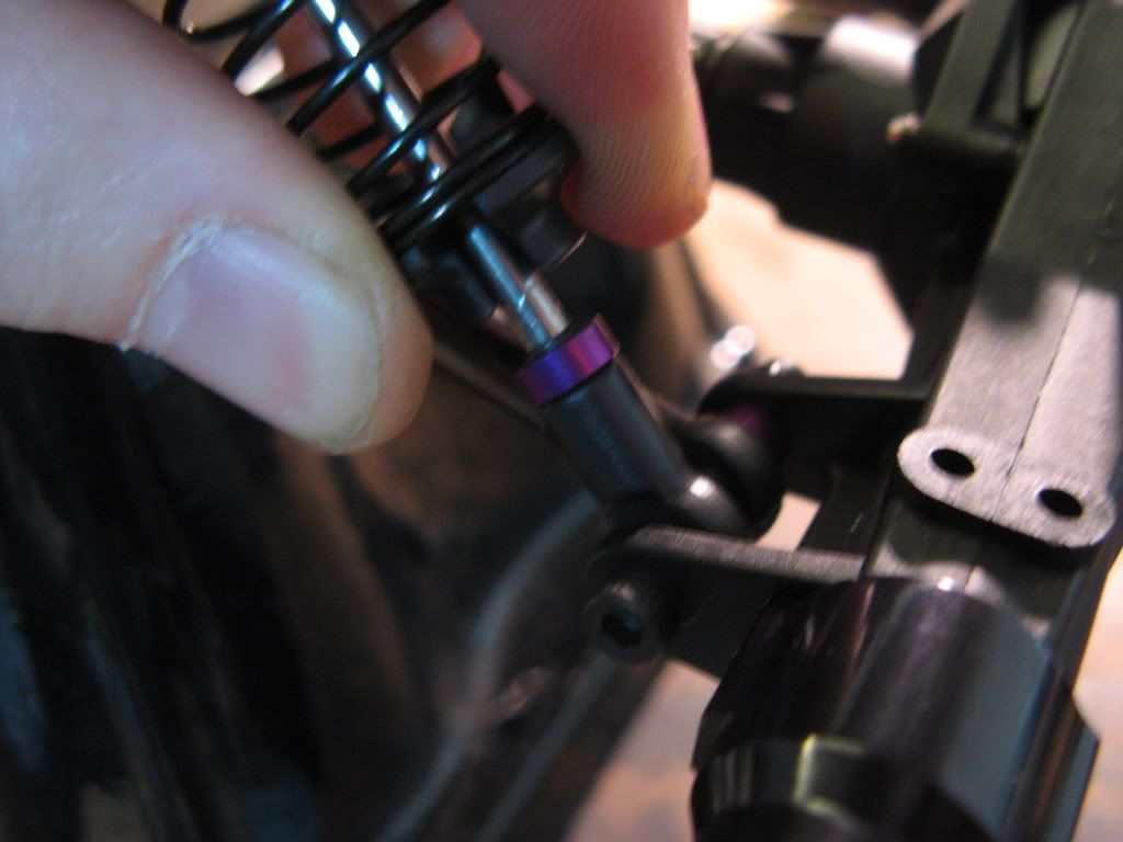 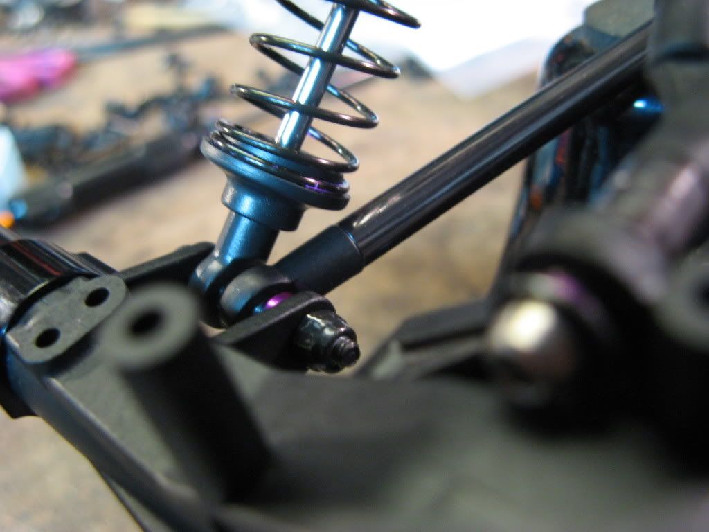 Last edited by Jesse Robbers; 12-27-2008 at 03:04 PM. |
|
| |
|
12-27-2008, 02:23 PM
| #3 |
| Quarry Creeper Join Date: Mar 2005 Location: THE WAING
Posts: 323
|
Look's good. How do you like the swx chassis?
|
|
| |
|
12-27-2008, 02:23 PM
| #4 |
| Pebble Pounder Join Date: Nov 2008 Location: Cincinnati, OH
Posts: 111
|
After some reading and searching, I bought what seemed to be the "best" dig tranny out there...the DNA dig. It looks good, but I am not happy with a handful of issues with it for the price of the unit. If it was sold at a cheaper price then it'd be OK. I feel for the price of it, better material and machining/fixture setup should be used. When it comes to certain items in a car (like transmissions and shocks) I feel that it should not be left up to the consumer to make it work "right". Those items are too sensitive to small tolerances to perform right that most or all people cannot achieve with simple tools. One of the 1.5mm holes stripped out very easily. I chose to re-tap the holes to 2-56 and use the slightly larger 2-56 size screws in place of the 1.5mm size screws. Then you need to drill the through hole slightly larger in the other outdrive half. The 2-56 is on the right side of this photo. The 1.5mm tapped holes on my outdrive half were not drilled concentric to the part either. 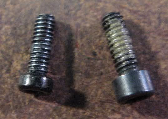 Shows the 2-56 screws installed. The diameter where the outdrive bearings ride on the DNA outdrive halves has been made too small. The bearing fit is too loose/sloppy. This part would be better off if made from steel to prevent the driveshafts from coming loose over time as the set screw "digs" into the soft aluminum. 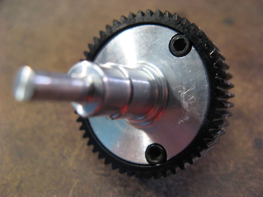 After I had everything installed, I noticed my transmission was free and smooth when the dig was not "active", meaning nothing in the dig was working/spinning. When I was in 4wd and the dig was "active", it would have a very tight spot. I don't have access to a mill to re-drill the holes on the outdrive to be concentric, so I did some more looking at the parts within the dig to see if anything else was "off" and this is what I found. The screw on the right side of the photo is stock, the screw on the left side is the hole I drilled. The stock screw hole for the set screw was drilled at a bad angle and caused this part to wobble a bit as it spun. I wasn't able to make the new hole exactly straight, but it's leaps and bound better than the stock hole. The stock hole almost bleeds through into the radius pocket on one side. 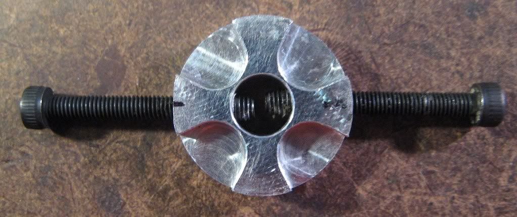 Last edited by Jesse Robbers; 12-27-2008 at 03:11 PM. |
|
| |
|
12-27-2008, 02:35 PM
| #5 |
| Pebble Pounder Join Date: Nov 2008 Location: Cincinnati, OH
Posts: 111
|
Transmission assembly modifications. The purpose of this was a number of things. #1 To make everything more compact to allow for more room in the chassis. #2 I wanted to modify the top shaft on a lathe and one of those magnetic top grinding stone machines to use a Losi or Associated style 1/10 off-road slipper to make everything more compact and have a dual disc slipper. Access to those this time of the year for me is bad, so I settled for a top shaft modification that isn't as compact but allows for the use of spur gears larger than 90t in size. I don't think Losi or AE makes spur gears larger than 90t for their slippers. So this might be better in the long run/overall picture. #3 Reposition the whole transmission assembly towards the center/left of the chassis and forward to place the weight better and allow for more room on the chassis. First I removed the stock 7mm or so thick grey shims between the motor plate and tranny case. Using 4mm worth of shims it places the motor plate against the tranny case. You can also see the new hole in the top shaft for the pin that engages into the slipper plate. The hole with the pin in it is 2mm inward from the middle hole. I don't remember how much further it is from the stock hole, looks to be about 5mm+ I'd guess. 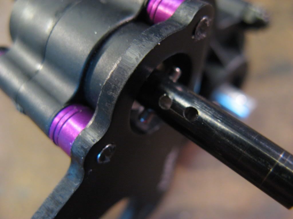 I had to sand the slipper plate narrower a bit to allow it to be positioned closer to the motor plate. The total width I think is now 5mm from the small to large side of the plate. 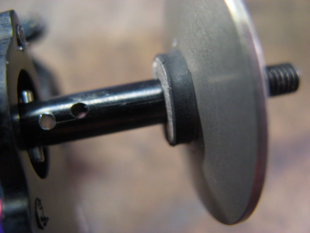 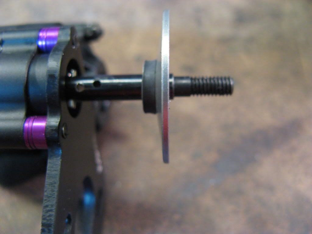 Last edited by Jesse Robbers; 12-27-2008 at 03:15 PM. |
|
| |
|
12-27-2008, 02:41 PM
| #6 |
| Pebble Pounder Join Date: Nov 2008 Location: Cincinnati, OH
Posts: 111
|
Shows how tight/compact the slipper assembly is now. 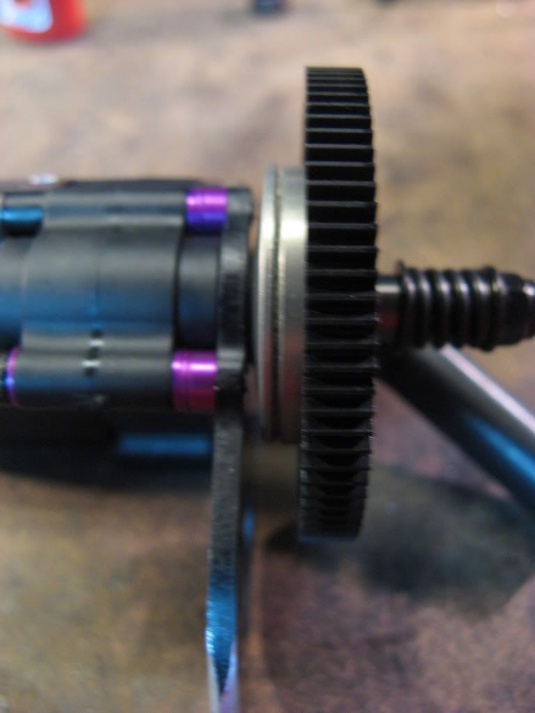 With the whole transmission stock, I had to sand the bell part of the MIP driveshaft smaller a bit b/c it would contact the spur gear a little bit. In this photo by doing the tranny mods, I now have a good amount of room to go larger on the spur gear. I have to wait for my orders to show up to know how much larger I can go on the spur gear size. 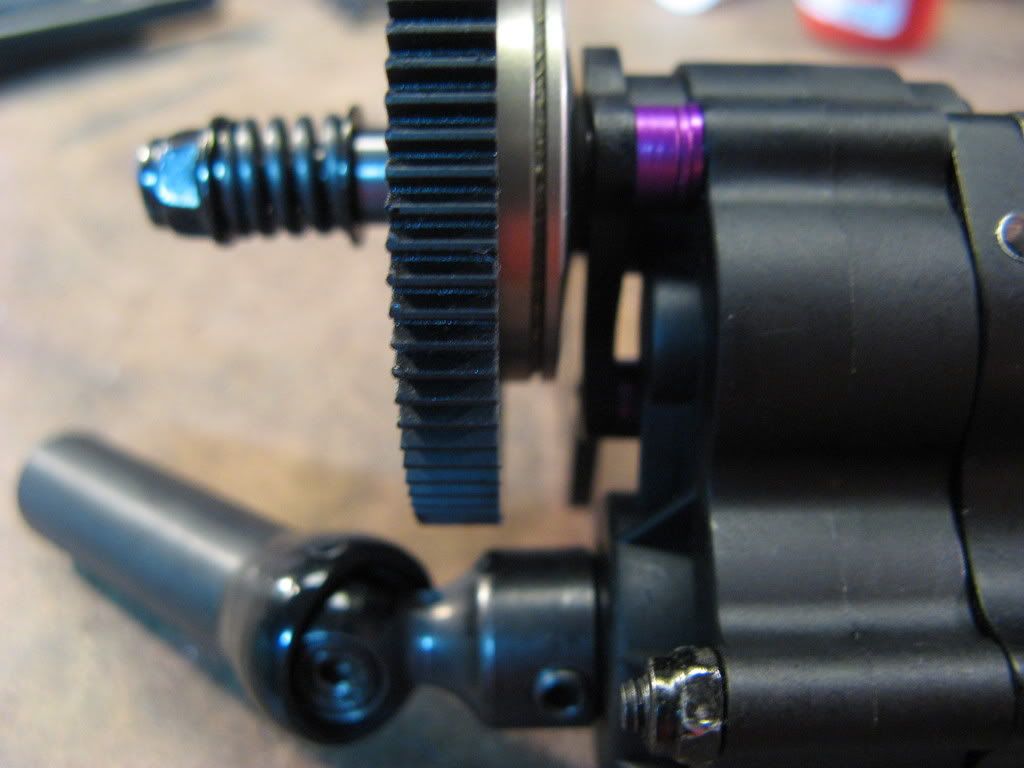 Had to add a spacer on the outside of the spur gear to allow for a proper setting on the slipper. Also had to use some thin .1mm or .2mm thick type shims between the slipper plate and tranny case bearing to shim it well. 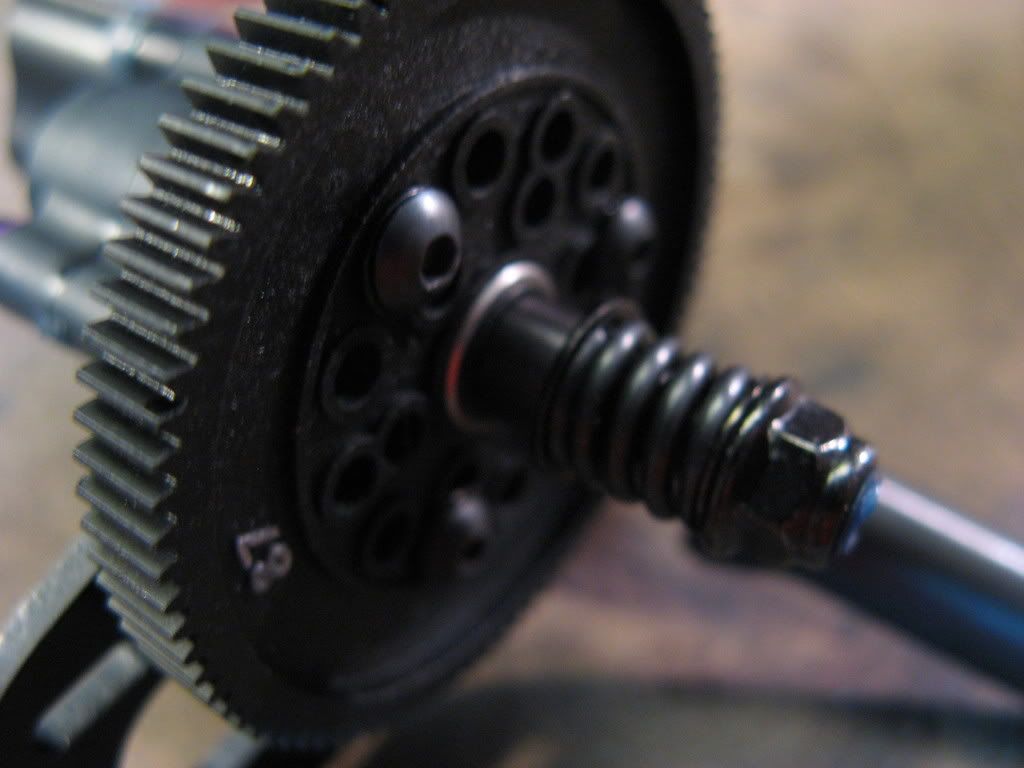 Different angle and it shows the rounded edge of the motor plate to slide over things a bit better. 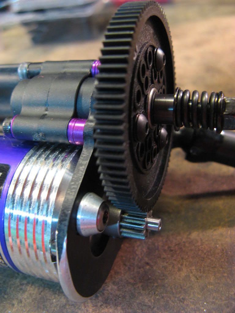 Last edited by Jesse Robbers; 12-27-2008 at 03:17 PM. |
|
| |
|
12-27-2008, 02:45 PM
| #7 |
| Pebble Pounder Join Date: Nov 2008 Location: Cincinnati, OH
Posts: 111
|
Different angle. 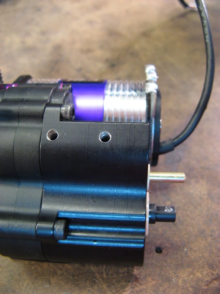 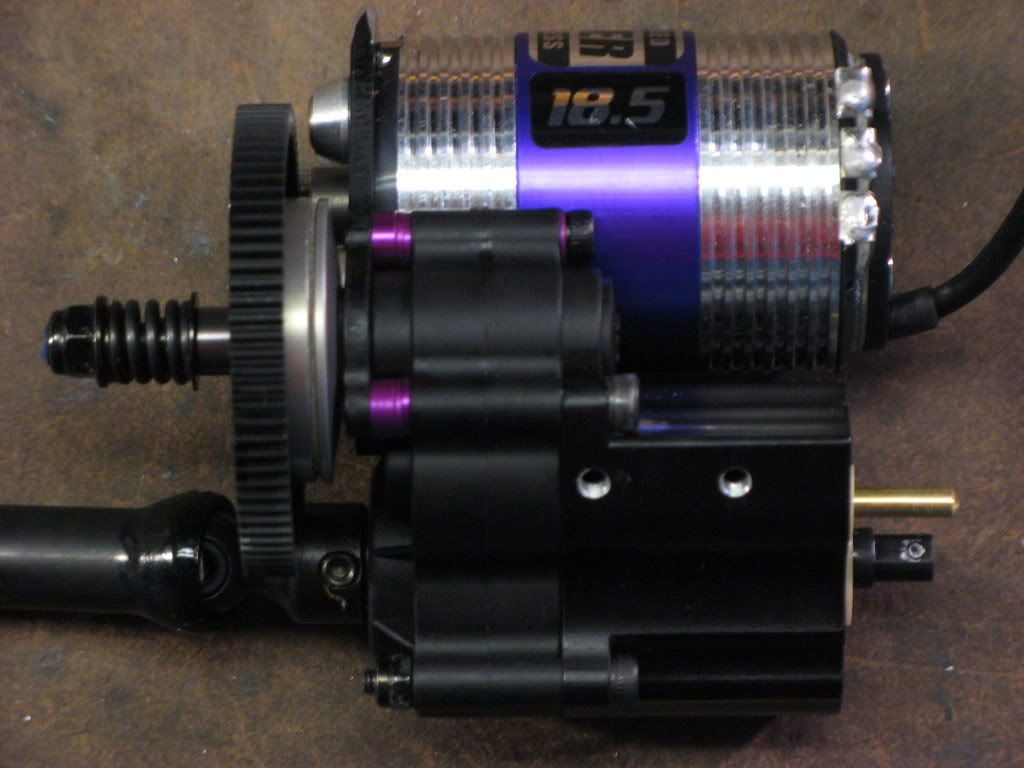 The tranny/dig assembly has been moved 12mm to 12.5mm forward and 5mm to the left side. That's about as far forward that I wanted to go however I would have liked to go to the side a bit more but driveshaft clearance for the upper link screw and running out of material on the side of the skid plate kept me from going further. The motor ends up being about 9mm further forward than it's stock position because of the motor plate being mounted closer to the tranny case. I might be able to lower the whole tranny assembly (dig & motor) 1.5mm by cutting a pocket into the top of the skid plate, depends on how mill access works out. 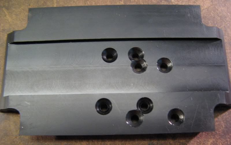 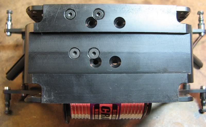 Had to cut some material off the chassis side plate to make room for the spur gear. The armature almost touches the side plate and leaves just enough room so that if I choose to mount the upper links on the inside of the side plates they will not touch the armature shaft. 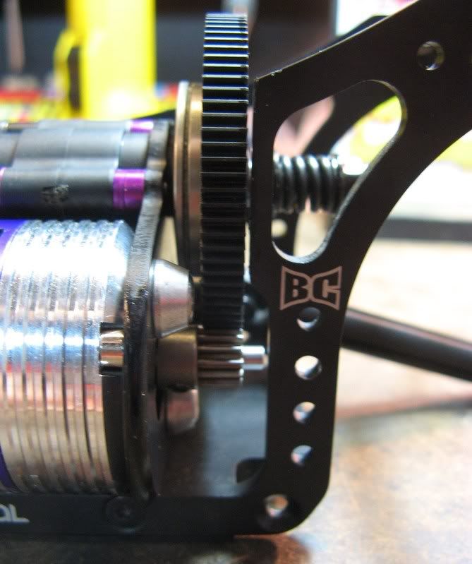 Last edited by Jesse Robbers; 12-27-2008 at 03:22 PM. |
|
| |
|
12-27-2008, 02:58 PM
| #8 |
| Pebble Pounder Join Date: Nov 2008 Location: Cincinnati, OH
Posts: 111
|
One of the new tranny holes in the skid plate ran through the center of the stock holes on the side plate. So had to make a new hole for one of the side screws. Also shows the tranny case resting against the chassis side plate and the material removed to make room for the "bulge" part of the tranny/dig cases. Figured I'd cut off only what was needed to fit the tranny for now, I may need the material on the side plate to mount or rest something against it further down the road. Jar of black paint + a Q-Tip to paint any areas on the motor plate or chassis side plates I cut to make it look "stock". 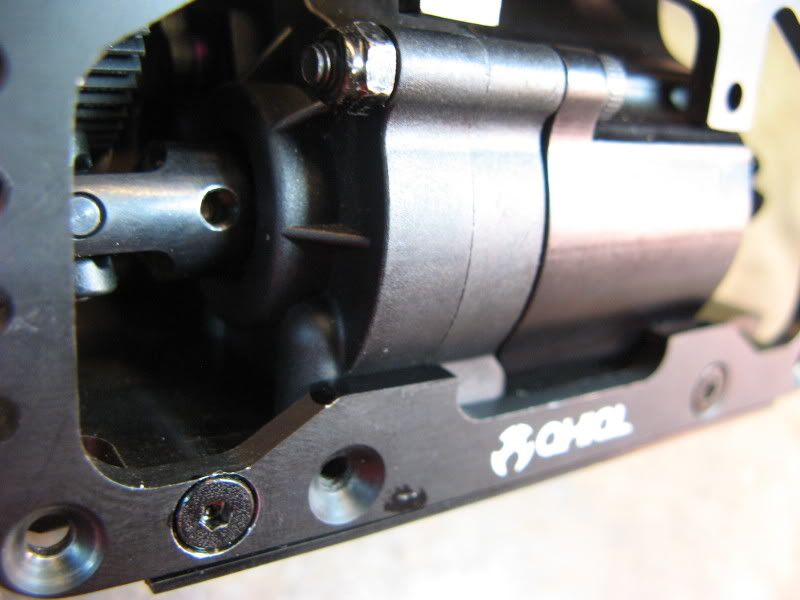 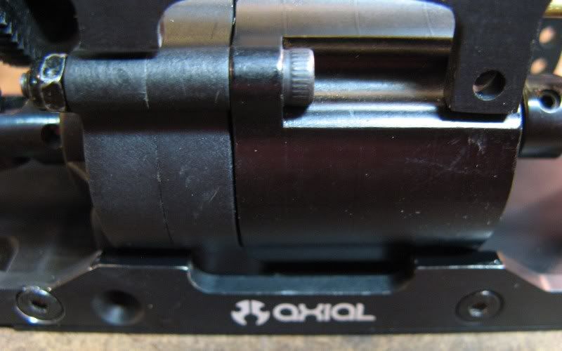 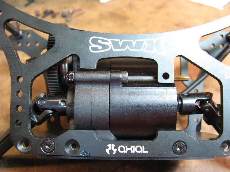 Forced to put the stock driveshafts on for now with the male end cut shorter to fit. The splines in the female MIP driveshafts don't run deep enough for how much shorter I need to cut the f/r driveshafts. I would only have about 1mm worth of splines to engage the male driveshaft into. So I must wait for the shorter/dig MIP ones to show up which should fit well. 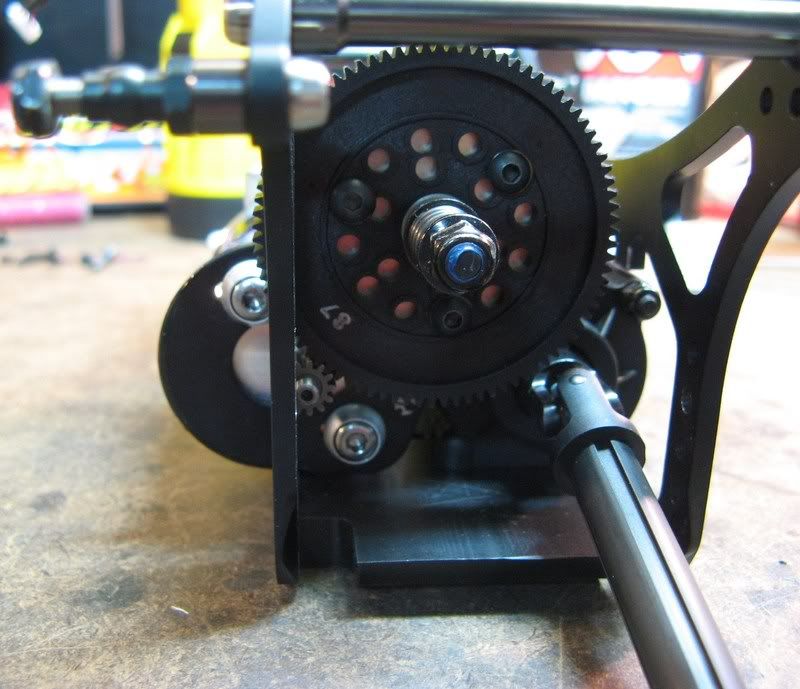 Plenty of room to place a std size servo behind the motor for the dig. I'm undecided as to using a std size low-profile servo(shorter in height) or a micro sized servo for this. 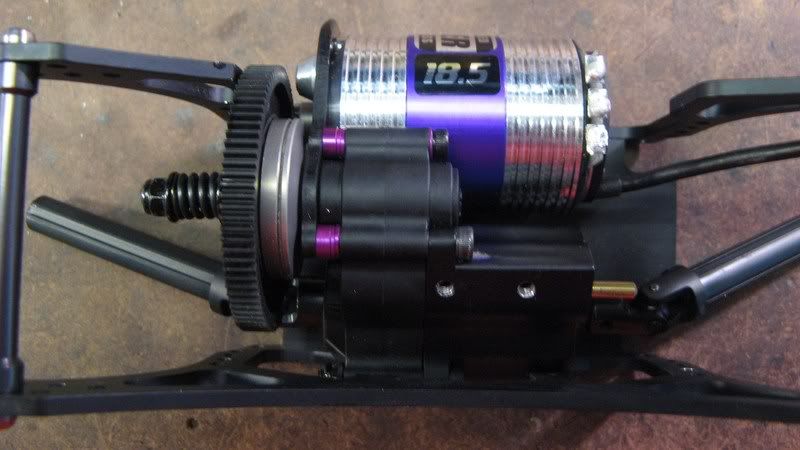 Last edited by Jesse Robbers; 12-27-2008 at 03:28 PM. |
|
| |
|
12-27-2008, 03:06 PM
| #9 | |
| Pebble Pounder Join Date: Nov 2008 Location: Cincinnati, OH
Posts: 111
| Quote:
Last edited by Jesse Robbers; 12-27-2008 at 03:29 PM. | |
|
| |
|
12-27-2008, 03:11 PM
| #10 |
| Newbie Join Date: May 2004 Location: gp,oregon
Posts: 3
|
DANG That trucks CLEAN! Its all Hb with the black and purple. Thats Sweet! |
|
| |
|
12-27-2008, 04:32 PM
| #11 |
| MODERATOR   Join Date: Jul 2004 Location: Ohio
Posts: 18,928
|
Looks pretty good Jesse, way to jump in with both feet! I'm most impressed with your little spacer under the spring cups. Brilliant.  |
|
| |
|
12-27-2008, 07:23 PM
| #12 |
| Rock Crawler Join Date: Sep 2004 Location: South Orange County
Posts: 589
|
that is a tight fit but it turned out great.
|
|
| |
|
12-27-2008, 07:28 PM
| #13 |
| RCC Addict Join Date: Nov 2008 Location: Bunnell, Fl.
Posts: 1,292
|
Nice job man! |
|
| |
|
12-28-2008, 12:39 PM
| #14 |
| Pebble Pounder Join Date: Nov 2008 Location: Cincinnati, OH
Posts: 111
|
Thanks y'all! There's still more work/pictures to go, just have to wait for parts to show up.
|
|
| |
|
12-31-2008, 08:18 PM
| #15 |
| Pebble Pounder Join Date: Nov 2008 Location: Cincinnati, OH
Posts: 111
|
Got some new parts today. Put the HD gears in the axles, aluminum spindles and caster blocks, Thunder Tech MIP short/dig length driveshafts f/r fit great after the tranny position change I made. A little dremel w/cut-off wheel + a drill press = a redneck lathe to make room on the MIP part for the larger spur gear. 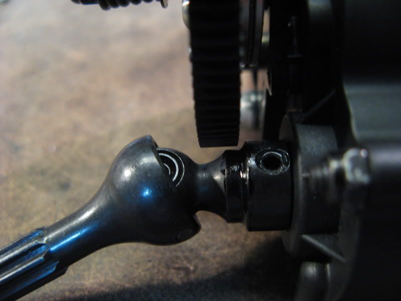 Geared 14/96 right now, gear mesh was a little too tight with the motor slid all the way over, had to elongate the motor screw holes a bit in the motor plate. 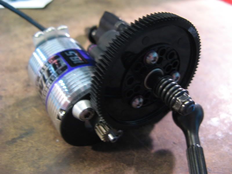 A few shots of the speedo mounted on a thin bent cheap aluminum plate material. I can't really "finish" routing the speedo wires until after I install the dig servo and the front axle plate for the battery and servo. Not sure if want to run the battery wires between the motor/tranny case on the skidplate or above the tranny case against the chassis side plates...depends on where a servo stretcher I have to use will hide the best on the chassis. 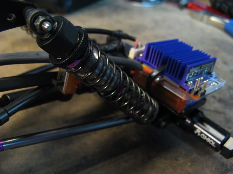 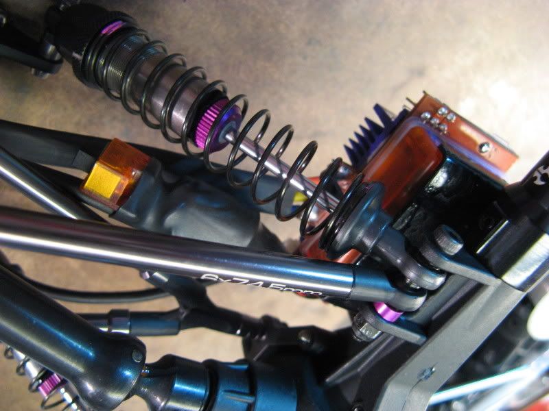 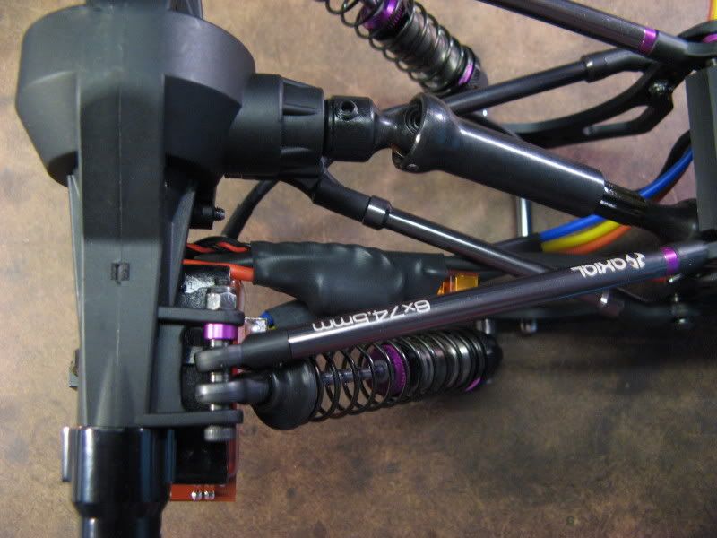 Last edited by Jesse Robbers; 12-31-2008 at 08:23 PM. |
|
| |
|
12-31-2008, 08:33 PM
| #16 |
| Rock Crawler Join Date: Apr 2008 Location: Highlands Ranch, Co.
Posts: 852
|
Nice build.When you moved the tranny over do the drive shafts have a angle to them going to the axles now? The tranny in the stock SWX location has the shaft going straight to the axles & that driveline position is the best as it does not bind the shafts & will let the DNA DIG work better. It's kind of like the angle of the driveshafts on the rear of a 2WD Off-Road buggy when viewed from above, more angle, more bind & locks the suspension.
|
|
| |
|
12-31-2008, 09:16 PM
| #17 |
| Pebble Pounder Join Date: Nov 2008 Location: Cincinnati, OH
Posts: 111
|
Yeah the driveshafts are at more of an angle now after moving the tranny over. It is about 10mm from the center of the pinion/input gear in the axle to the diff axis in the tranny. I moved the tranny to the side 5mm so stock the SWX chassis may have had about a 5mm off-set in the driveshaft. Currently I am more worried about the weight placement than the dogbone angle bind. After I run the truck I might have to move it over to the right side if it binds bad enough so the dig doesn't work properly.
|
|
| |
|
12-31-2008, 09:38 PM
| #18 |
| Shelf queen   Join Date: Aug 2008 Location: Internet
Posts: 5,857
|
Excellent work Are you planning on using the stock dig mount that DNA provides or are you gonna fab something up?
|
|
| |
|
12-31-2008, 09:42 PM
| #19 |
| Rock Stacker Join Date: Oct 2005 Location: Fairfeild - Travis AFB- NorCal
Posts: 59
|
smooth setup, Bender make some nice products
|
|
| |
|
01-01-2009, 12:20 PM
| #20 |
| Pebble Pounder Join Date: Nov 2008 Location: Cincinnati, OH
Posts: 111
|
I'm planning on putting the dig servo onto the skid plate behind the motor/tranny. I don't want to put the servo up high on top of the tranny and I don't think there's room to put it there now. If I use a micro 1/16 sized servo for the dig, then I might use the DNA servo mount screwed to the side plate or something. I have to wait a few weeks before for the servo to arrive before mounting it.
|
|
| |
 |
| |


 Linear Mode


