| |
| |||||||
 |
| | LinkBack | Thread Tools | Display Modes |
 05-22-2009, 04:21 PM
| #1 |
| Quarry Creeper Join Date: Sep 2007 Location: Central Coast, NSW, Australia
Posts: 277
|
Hey guys, I put this up on my home forum, but seeing as I couldn't find anything on here about it, I thought I would put it up here too. As the title states, I've added another cell to a 3 cell lipo to create a 4 cell pack. The reason I added the extra cell myself instead of buying a 4s pack was compactness. The smallest 4s pack I could find was over 2000mah, and there was no way it was going to fit into my chassis. So I picked up a couple of 1500mah 3s packs and went to work.... NB. While this is a bit of a how-to, it does not cover everything, especially all the safety measures that one should put in place while attempting something like this. Ergo, I don't take any responsibility for setting your house on fire or any inaccuracies/dodgyness I may exhibit. As mentioned, I picked up a couple of 3s packs to start with. Not being an expert, I'm only guessing that its probably a good idea to pick cells of the same size/type. Started out looking like this: 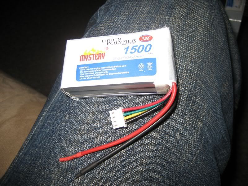 And I picked up a few of these 4 cell balancing harnesses. I could only buy 10 as a minimum, I wont need all 10 so if anyone else wants some, let me know. The black goes to - on the battery, the red goes to the +, and each of the other colours goes to each +/- junction between each cell. 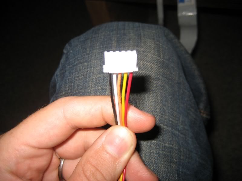 First thing to do is strip off all the insulating tape on both batteries. This is what it looks like nude, and this is when you should start treating all bare wires with respect. I've accidentally shorted a lipo cell in my hand once, and it will go up in flames before you can let go of it. 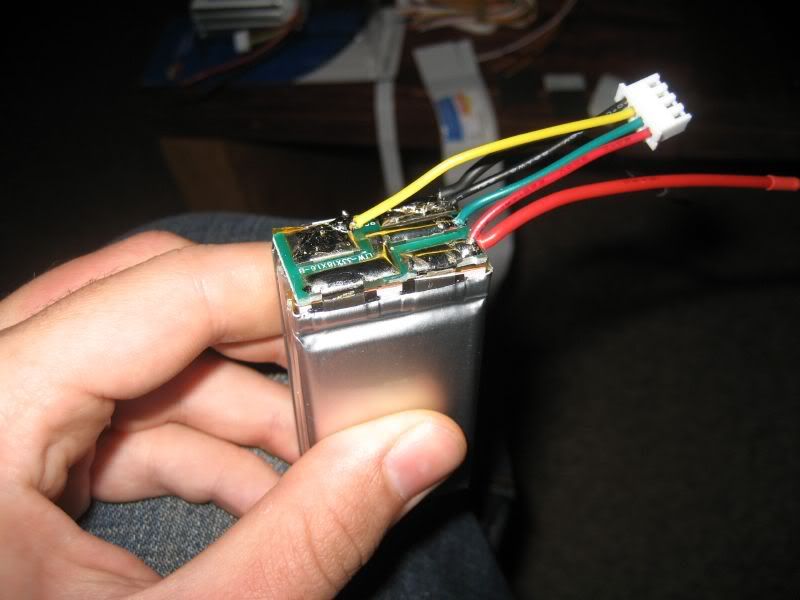 Next job is to split off one cell. I chose to separate the cell before desoldering it as it makes desoldering easier, as you can pull the cell away as you hit it with the soldering iron. I split the cell off by getting a thin, sharp knife and cutting the double-sided tape in half (thickness-wise). This method may not work for some batteries, you may be able to just peel them apart. When splitting the cells, take the utmost caution to make sure to don't puncture a cell or rupture the seal around the edge. Lipo cells are in a vacuum, letting the air in will mean no more workies. 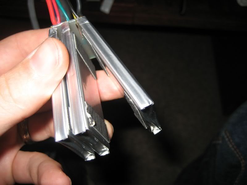 Here are the two batteries ready to go before getting the soldering iron out. 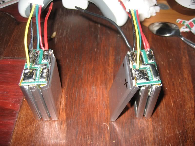 I then made the wise decision to move my operations down to the garage. The threat of setting something on fire is real, and I'd rather set my workbench on fire than my lounge. I've used my vice to hold the battery nice and steady (but not too tight) while performing the procedures. First procedure was to remove the transplant cell. Probably a good idea to write which tab is which so you don't forget polarity. 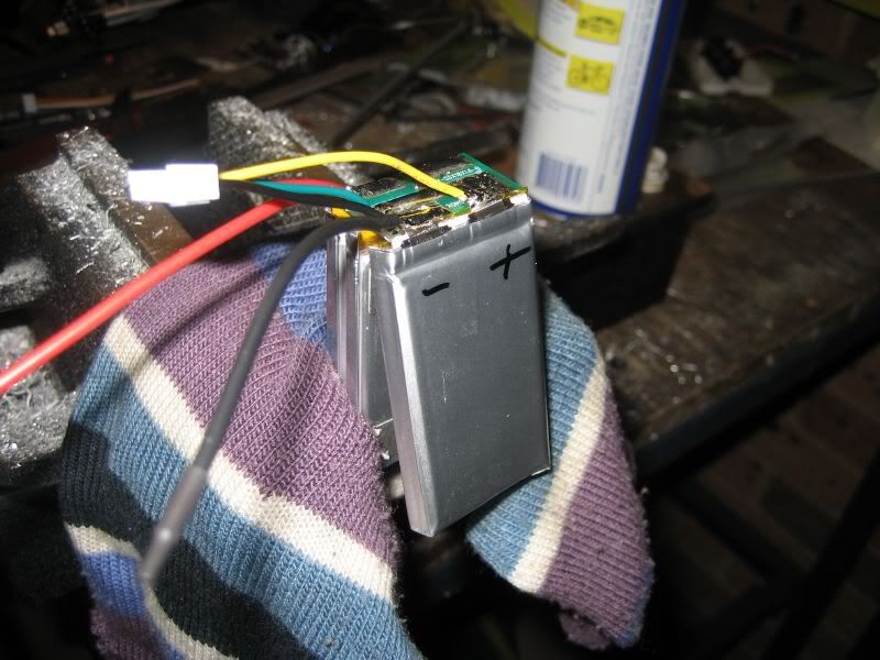 First thing I did was desolder the - battery wire and the balance plug wires that are attached to the cell to be removed. As I desoldered each wire, I snipped the bare end of the wire off so there was no chance of having a short on anything. I then set about removing the transplant cell by lightly pulling the cell and heating up the two solder joints. I alternate between the two tabs with the heat so that it gradually comes off and doesn't put any undue bending force on the solder tabs. 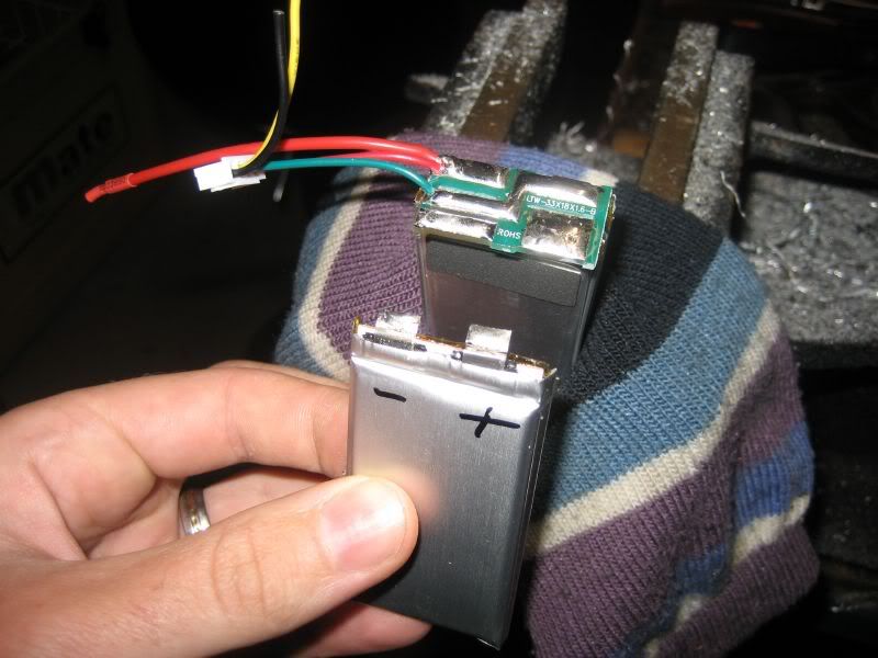 You can then put the donor battery and the transplant cell aside and get started on the recipient battery. In the vice again and desolder all of the wires one at a time. Make sure you don't short any cell with the iron while doing it, and DON"T FORGET POLARITY!! I also snipped the bare end of each wire as it came off for the aforementioned reason. 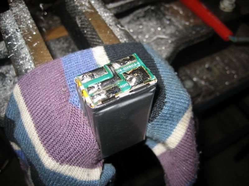 I then offered up the transplant cell to the recipient battery, and just lightly taped it into position. I added the extra cell to the - side of the battery, which means I had to connect the + from the transplant cell onto the last - terminal on the existing battery. Don't get it wrong. You can also see I've added an extra piece of tape between the transplant cells - terminal and the adjacent terminal, just to make sure there is no accidental short there. 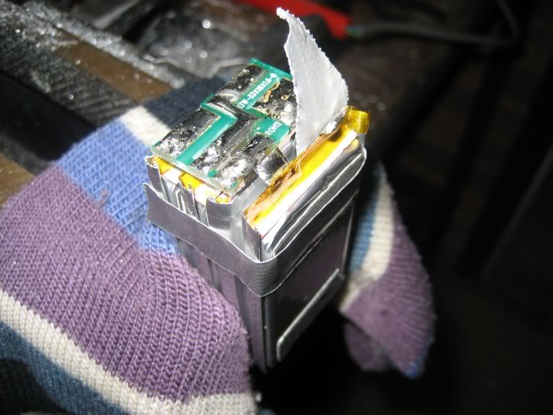 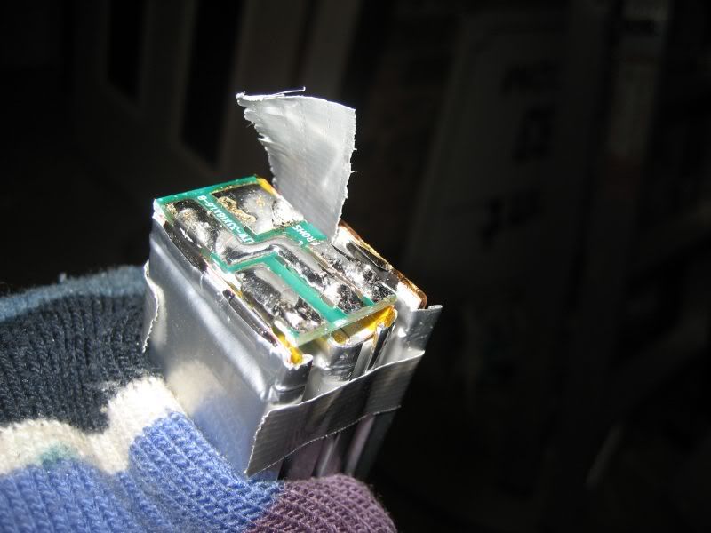 Then bend the transplant cells + tab over and solder it to the adjacent - tab. I'd be carefull not to get the tab too hot when soldering the two together. If in doubt about if its joined or not, I'd let it cool first and then have another go. 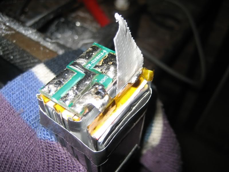 Next task is to add in the new balancing harness. Its actually quite a simple process, more on that in a sec. Just decide on a length for the harness and cut the first wire to length. In my case this was the red wire. I would recommend starting with the furthest away wire and working towards you. This way you aren't trying to reach over wires with the soldering iron - further reducing the chance of a short. Tin each wire as you cut and join it to make soldering the joint quick and easy.  As I mentioned up the top, wiring in the new balance harness is pretty straight forward. The red on one end, and the black on the other end go to the first cells + and the last cells - terminals. These are the same terminals that the actual output wires will get joined to too. The remaining three wires go to each of the +/- connections between each of the cells. Because all the cells are wired in series (hence the s in 3s), the - of each cell is joined to the + of the next cell (except the first and last terminal). Each one of these joins is where one of the balance wires gets attached. Not being an expert, I would say the charger knows the voltage of each cell by doing the following: measures cell 1 voltage across the black and first wire. measures cell 2 voltage by measuring across the black and second wires, which will give the combined voltage of the first and second cell. Then subtracts the measured voltage of the first cell to get the second cells voltage. measures each remaining cell in the same fashion by measuring the total and subtracting the preceding cell voltages. Anyway, end result is this. 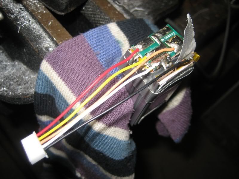 Then add the two output wires. Pretty straight forward there. I upgraded the old 18 awg wire with some beefier stuff so there are no problems there. Take care soldering the - output wire to the free - tab on the cell. Because all the recipient batterys cell tabs are soldered to the PCB, they are quite well protected from any forces on the output wires. But the transplant cells - tab isn't attached to any PCB and is therefore more suseptable to damage from force through the output wire. Its pretty well done then! At this point I'd recommend putting a multimeter across the battery to make sure everything is in order. 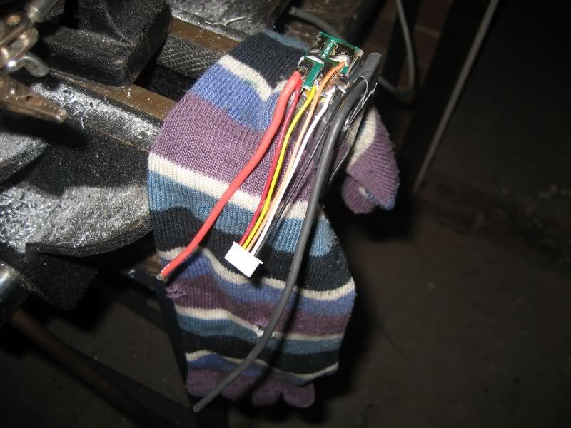 I then took it back into the house and added some of the tape back on, making sure that the transplant cell was well and truly secure to the rest of the battery. 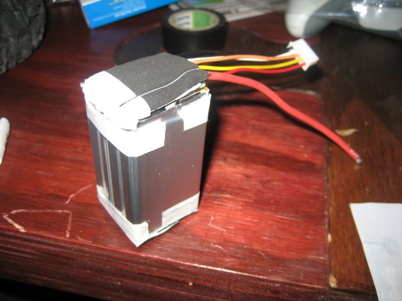 TTS factory leccy tape and put the spec sticker back on with some updated details. You can see (not really, its on the other side of the battery) how I've run the output wires down the length of the battery underneath the tape. This is to again provide more protection to that - tab on the new cell from the - output wire. 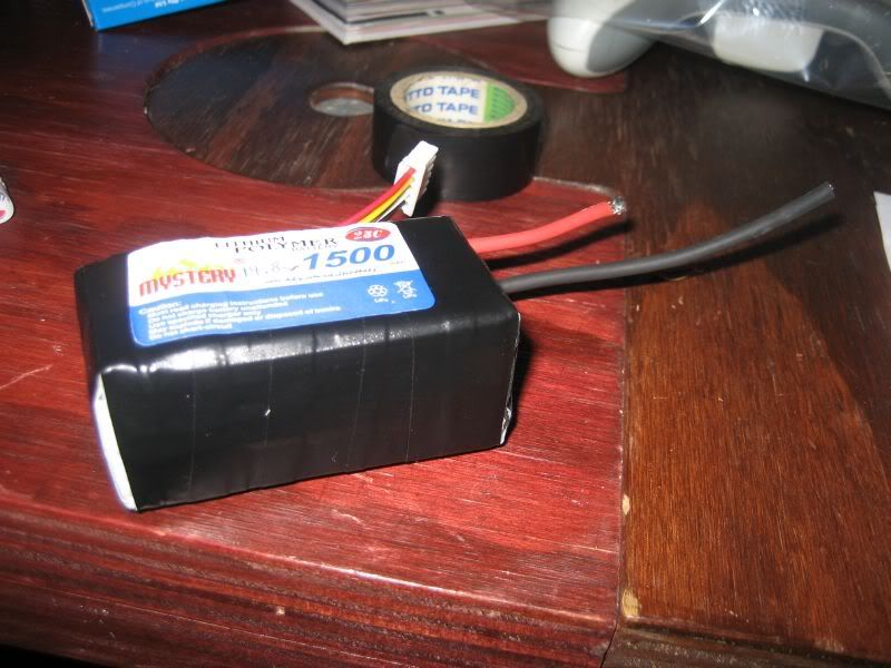 I then added my bullet connectors to the output wires and held my breath for the big moment - charging and balancing!! Yep, put it on the charger. Looked to be charging and balancing fine. I haven't given it a full charge yet, but if there are any problems, I will report back. Nice and snug in the chassis.  Now to give it some testing |

|  |
| Sponsored Links | |
| | |
|
05-22-2009, 05:49 PM
| #2 |
| Quarry Creeper Join Date: Feb 2009 Location: Richmond, VA
Posts: 379
|
very interesting thread. i like the concept. let us know how testing goes with the battery. can you get some more pics of the placement of the battery?
|
|
| |
|
05-22-2009, 06:43 PM
| #3 |
| I wanna be Dave Join Date: Oct 2006 Location: Centered
Posts: 2,082
|
14.8 in a Berg...should be nutty What are you running for motors and gearing? |
|
| |
|
05-22-2009, 07:02 PM
| #4 |
| Rock Crawler Join Date: Aug 2008 Location: Tucson
Posts: 625
|
Lipo scares me. Nice writeup, would like to see the follow up. That is 1 small 4's pack. Very nice.
|
|
| |
|
05-23-2009, 03:29 PM
| #5 |
| Quarry Creeper Join Date: Sep 2007 Location: Central Coast, NSW, Australia
Posts: 277
|
Sure, I'll get some more photos in the next day or two. Motors are two 55t venom fireballs (avoid if possible) and two 12t pinions. Ran it in a comp last weekend. Battery performed very well. Charged and discharged well, balanced perfectly - did everything a battery should! motors get a little warm when getting trigger-happy, but the battery never looked like it was going to have a problem. |
|
| |
|
05-23-2009, 04:19 PM
| #6 |
| Rock Crawler Join Date: Aug 2008 Location: maple ridge
Posts: 627
|
AWESOME TECH. always wanted to take one apart but never had the expendable cash to buy a bat and almost **** it up. the 2s 2200 batt i got no longer has balancing leads. THe balancing wires got tangled up in the tire and gounded otu on the aluminum knuckle. the wires went up in flames instantly. so i trimmed them off and hot glued them out the way. i've been using the bat liek this for a couple months now. I guess after reading this i can put some new leads on the batt. definatly something i'm not doign in my living room....the usual RC fab workshop. |
|
| |
|
05-23-2009, 05:54 PM
| #7 |
| Rock Crawler Join Date: Jul 2007 Location: central PA
Posts: 679
|
I run a 2200mah 4s in my Berg using 35t Warrior IIs. Watch the Sidewinder for getting warm though. Mine gets pretty hot so alot of times I let it cool halfway through cycling. Its a nasty setup for sure. Enough to flip backwards on the road or do donuts in the dirt. :-P |
|
| |
|
05-23-2009, 11:08 PM
| #8 |
| I wanna be Dave Join Date: Mar 2008 Location: Wayne county. PA
Posts: 2,507
|
why all the volts with a 4s pack....i started with elite 1500 nimh 10 cell 12.0 volt pack and cut that down to 8 cells at 9.6 volts cause the wheel speed with my 55t was way to much for me....i even turned down my throttle travel on my TX to tame it down more, the next step will be a smaller tooth pinion from my 17/87 gears now...............bob .... |
|
| |
|
05-24-2009, 06:23 AM
| #9 |
| Rock Crawler Join Date: Mar 2008 Location: Arizona
Posts: 578
|
I have been running 4s for about a year now. I use 2 2 cell packs in series to make the 4s. I run them on a Sidewinder and 55t motors. All the wheel speed I could ever need (I jump a lot of gaps when I crawl) and the control of 55t motors. My crawler is faster than 3s 35ts and has great low speed control.
|
|
| |
|
05-24-2009, 04:22 PM
| #10 | |
| Quarry Creeper Join Date: Sep 2007 Location: Central Coast, NSW, Australia
Posts: 277
| Quote:
   Wheel speed I think is a little more than needed, I would actually like to go down to a smaller pinion to boost low-speed control, but alas, I believe 12t is the smallest for metric pinions. | |
|
| |
|
05-25-2009, 09:21 AM
| #11 |
| Pebble Pounder Join Date: Dec 2008 Location: Tomball, Tx
Posts: 168
|
excellent tutorial! Thoroughly documented both pics and text. Thank you for your time and efforts.
|
|
| |
|
05-25-2009, 10:29 AM
| #12 |
| RCC Addict Join Date: May 2006 Location: enid
Posts: 1,250
|
I just ordered som zippy 7.4v lipo's 1300 for 8 bucks a piece and wired them together 14.8 rocks in a berg like so   |
|
| |
|
05-25-2009, 12:50 PM
| #13 | |
| Quarry Creeper Join Date: Feb 2009 Location: Richmond, VA
Posts: 379
| Quote:
| |
|
| |
|
05-25-2009, 03:48 PM
| #14 | |
| Quarry Creeper Join Date: Sep 2007 Location: Central Coast, NSW, Australia
Posts: 277
| Quote:
To connect the two batteries as above to achieve 14.8v you need to connect the negative of battery A to the deans connector, and the positive of battery A to the negative of battery B. Then the positive of battery B goes to the same deans connector. This is running the batteries in series, and what doubles the voltage (7.4v + 7.4v) To connect the two positives and two negatives together would be running the batteries is parallel. This would double the mah instead (1300 + 1300) and the voltage would remain 7.4v. There's really no limit to what you can go up to in a battery, just look at the aircraft guys with 9s and 10s (34v), but their motors and speed controllers are built to handle it. Going over 3s on anything other than a Castle Sidewinder or Mamba Max will just let the smoke out. | |
|
| |
|
05-25-2009, 04:49 PM
| #15 | |
| Quarry Creeper Join Date: Feb 2009 Location: Richmond, VA
Posts: 379
| Quote:
| |
|
| |
|
| |


 Linear Mode


