| |
| |||||||
 |
| | LinkBack | Thread Tools | Display Modes |
 04-27-2009, 09:57 AM
| #1 |
| Newbie Join Date: Feb 2009 Location: Edinburgh, Scotland. United Kingdom
Posts: 12
|
I purchased a Tekin FXR & 55T motor recently. The wiring seems simple enough for me to understand al least on the ESC connections, but I am a little confused as to where exactly to solder on the motor. There were 3 (assuming here) capacitors/resistors that came with the motor. Where do these go? If anyone can explain what exactly goes where on the image below I would greatly appreciate it. Thanks in advance. 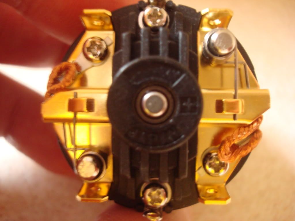 |

|  |
| Sponsored Links | |
| | |
|
04-27-2009, 10:00 AM
| #2 |
| Quarry Creeper Join Date: Feb 2008 Location: Rhode Island
Posts: 275
|
The side with the + means you solder the red wire to one of those 2 posts, doesent matter which as you can see they are a solid piece of metal. The other side is the black wire. THose little resistor things arent usually needed, I believe people use those if their setup is glitchy.
|
|
| |
|
04-27-2009, 10:03 AM
| #3 |
| Rock Crawler Join Date: Mar 2009 Location: Victoria BC
Posts: 988
|
pick one post on the left and one on the right (posts are the things at the top and bottom of your pic) then if your forward controll sends you backwars you can a) swap wires left to right b) reverese the signal on your controll by fliping the throttle switch to rvs
|
|
| |
|
04-27-2009, 10:07 AM
| #4 |
| Quarry Creeper Join Date: Oct 2007 Location: Toronto, ON. Canada
Posts: 281
|
there are two connectors per brush. just make sure you have positive to one motor brush and negative to the other brush. if the motor spins in reverse, swap the motor wires. if you are refering to the caps that came with the motor . saulder them a such. cap 1 - positive to negative cap 2 - positive to ground cap 3 - negative to ground positive and negative is obviously on the brushes, and negative i solder to the can its self. but the small screws in between the brushes can be used as ground also. if you are using a 2.4ghz remote you dont need to add these caps to the motors. but it doesnt hurt either, so do it if it makes you feel beter. |
|
| |
|
04-27-2009, 10:32 AM
| #5 |
| Newbie Join Date: Feb 2009 Location: Edinburgh, Scotland. United Kingdom
Posts: 12
|
Thanks for info guys. Im running with a Nomadio React so hopefully I wont get any interference. If I do, I now know where to solder them. Cheers. In theory, I could solder the wires for the motor to an eyelet and just use the phillips head screws to hold in place? (10 & 4 oclock position) Last edited by flake99please; 04-27-2009 at 10:35 AM. |
|
| |
|
04-27-2009, 10:58 AM
| #6 |
| Newbie Join Date: Apr 2009 Location: Knoxville, TN
Posts: 25
|
This thread is actually a ton of help to all newbies!! (namely me)
|
|
| |
|
04-27-2009, 01:42 PM
| #7 |
| Pebble Pounder Join Date: Nov 2008 Location: Prescott
Posts: 114
|
This may help too. Just a visual for buzzkilla's post.
|
|
| |
|
| |


 Linear Mode


