| |
 08-06-2009, 08:14 PM
| #1 |
| Quarry Creeper Join Date: Jun 2008 Location: Hell
Posts: 399
|
I don't know if anybody else does this but relized I could make a pico/relay switch out of the circuit board from a servo. I just made an led bar so this helps with testing it. I just took out the motor and pot and wired the pot leads with 2 2.2k resistors and shortened the board and soldered my led leads to where the motor leads were.  What are your thoughts? What are your thoughts?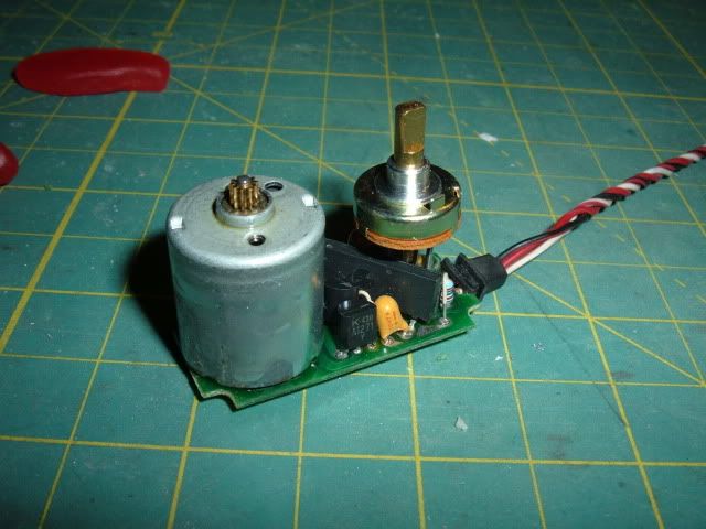 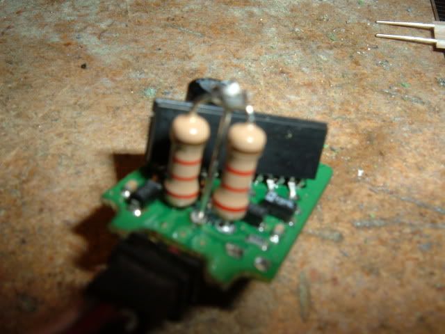 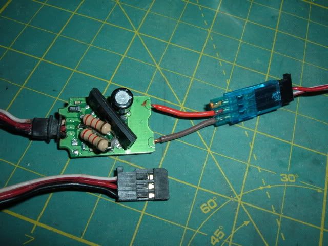  |

|  |
| Sponsored Links | |
| | |
|
08-06-2009, 09:27 PM
| #2 |
| Pebble Pounder Join Date: Nov 2006 Location: vaca, nor cal
Posts: 134
|
Sooooo, What does this do again?
|
|
| |
|
08-06-2009, 09:38 PM
| #3 |
| Rock Crawler Join Date: Sep 2008 Location: Kennesaw
Posts: 630
|
You dont say.....
|
|
| |
|
08-06-2009, 09:51 PM
| #4 | |
| Quarry Creeper Join Date: Jun 2008 Location: Hell
Posts: 399
| Quote:
A pico switch is like $20 new so I made one. I don't kno that much about electronics so I'm pretty happy that all the stuff I've been wiring, has worked lately (knock on wood) I've got a video of lighting up the leds by remote too (if u wanna see it)
| |
|
| |
|
08-06-2009, 10:17 PM
| #5 |
| Rock Crawler  Join Date: Mar 2009 Location: West of Eugene, OR
Posts: 942
|
The servo's PC board doesn't care what it's powering, so it sends power to the LEDs... Sounds cool to me. Way to use your head; that's a great way to recycle a down/stripped servo.
Last edited by JeepinOR; 08-06-2009 at 10:20 PM. |
|
| |
|
09-01-2009, 09:47 AM
| #6 |
| I wanna be Dave Join Date: Oct 2008 Location: Golden
Posts: 2,588
|
Cool use of an otherwise useless part. Were the resistors there to keep the servo "pot" centered? If so, I'm heading to the shack to go pick some up... So, help explain how this works in the truck... Servo Centered = Lights off Servo off center = Lights on? Or is there two switches here? Servo Centered = lights off Servo Left = Light 1 on Servo Right = Light 2 on? I plan on using the old servo case so I can waterproof this part of it. The LED wires will just come out of the servo output hole on the top of the case, sealed with silicone. Also the mounts make it easy to make a mount for it. |
|
| |
|
09-01-2009, 11:04 AM
| #7 |
| Rock Crawler Join Date: Feb 2008 Location: UK
Posts: 818
|
The resistors are there to replace the pot, as you realised. The servo PCB will keep driving the load (motor, LEDs or whatever) until the pot reaches the point that the radio wants to send it to. With resistors replacing the pot, the PCB just keeps on driving, so your LEDs stay lit. A device like this can only be used as an on/off switch, unless you add some extra electronics. With the Tx switch/stick centred at neutral, the PCB won't power the load. Move the switch, and the PCB will power the load. Move the switch/stick the other way, and the power will be reversed, blowing your LEDs. |
|
| |
|
09-01-2009, 07:45 PM
| #8 |
| I wanna be Dave Join Date: Jan 2006 Location: ...the burning end of the rope.
Posts: 5,013
|
ive used this technique before works great. you can also use a dpdt center off relay with the servo board to drive heavier loads than what the board will handle,,the only problem with the method above is that in one direction the pcb puts out forward voltage and the direction it puts out revese voltage so diodes are strong saftey item to keep reverse polarity from being an issue. you can also wire one item to the leads regularly so it gets forward voltage and wire another item in reverse so it gets forward voltage when the output voltage reverses Last edited by rmdesignworks; 09-01-2009 at 08:01 PM. |
|
| |
|
09-01-2009, 08:07 PM
| #9 | ||
| I wanna be Dave Join Date: Oct 2008 Location: Golden
Posts: 2,588
| Quote:
I was planning on using this method to power my 3-Racing LED control unit. Still trying to figure that one out. I don't think I would want the lights on all the time. If I can't figure that out, I'd probably use the PicoServo Switch to turn on and off the rock lights (roof lights, etc) and leave the controlled lights on all the time. Quote:
Also, using the relay, I wouldn't have to worry about reverse voltage, since the relay coil should power in either voltage direction. Right? | ||
|
| |
|
09-01-2009, 08:12 PM
| #10 |
| I wanna be Dave Join Date: Jan 2006 Location: ...the burning end of the rope.
Posts: 5,013
|
most relays are polarity sensitive,,connect a diode between the outputs of the relay and the servo pcb and you dont have to ever worry about it,,and no you wouldnt need a dpdt relay for your lights a spst would work fine,,i would recommend a override switch in the battery circuit though just in case,,using the pcb only method would work too for your lights but yet it would drain your bats unless you power the pcb seperately,then only the signal wire is connected to the rx
|
|
| |
|
09-01-2009, 08:14 PM
| #11 |
| I wanna be Dave Join Date: Jan 2006 Location: ...the burning end of the rope.
Posts: 5,013
|
a dpdt would be useful if you wanted to like wire a 2 wire winch to it with diodes with a seperate battery,,,
|
|
| |
|
09-01-2009, 08:59 PM
| #12 |
| I wanna be Dave Join Date: Oct 2008 Location: Golden
Posts: 2,588
|
OK, not wanting to hijack the thread, hope the info adds to the thread rather than take away from it... Never dealt with negative voltage before in my electronics building, so what should I look for in a diode? And where to wire it? Positive wire? Negative wire? And I haven't pulled the multimeter out to test it yet, but what voltage is the pcb putting out on the motor? (helps in finding the right relay.) |
|
| |
|
09-01-2009, 09:12 PM
| #13 |
| I wanna be Dave Join Date: Jan 2006 Location: ...the burning end of the rope.
Posts: 5,013
|
hook up the pcb like normal to a rx then run your radio stick one way then the other while your meter is hooked to the motor leads,,,one way will put out a reading of voltage which is positive or forward voltage and the other way the reading will show a (-) voltage,,thats the reverse voltage,,,diodes only work in one direction so you wire the forward diode to the positive lead and the reverse diode to the negative lead,,this way the voltage can not reverse though the relay,,diodes have a band around the side that follows the flow of current,,the forward diode will have the band closest to the relay while the reverse diode will be closest to the pcb,,,allowing current to flow through them one way not the other, protecting the relay or whatever you hook to it,,for instance the forward diode would connect to the positive (anode) lead of an led circuit, the reverse diode would connect to the negative (cathode). because of the circuit load you could probably use an 1/8th watt diode rated for at least 6vdc |
|
| |
|
09-01-2009, 11:06 PM
| #14 | |
| I wanna be Dave Join Date: Oct 2008 Location: Golden
Posts: 2,588
| Quote:
So, 2 diodes, making sure they are in the right direction... Got it! | |
|
| |
|
09-02-2009, 12:27 AM
| #15 |
| Rock Crawler Join Date: Feb 2008 Location: UK
Posts: 818
|
Monkeyracer: You could just leave the pot on the PCB. Replacing it with resistors saves weight and space. Also means you've got a spare pot to use in other projects. rmdesignworks: What's a DPDT centre off relay? I've only seen DPDT changeover relays. I'm guessing that it'd have 2 coils - have you got a link? Are you suggesting diodes as a means of protecting against accidental reversal, or using them to make a 3-position servo switch? |
|
| |
|
09-02-2009, 06:30 PM
| #16 | |
| I wanna be Dave Join Date: Jan 2006 Location: ...the burning end of the rope.
Posts: 5,013
| Quote:
You can make a 3pos switch like that yes,,,but what it also does is keep seperate circuits seperate,,like an led circuit and a dig circuit | |
|
| |
|
09-15-2009, 10:42 PM
| #17 |
| I wanna be Dave Join Date: Oct 2008 Location: Golden
Posts: 2,588
|
can you give me a link to an example diode? they aren't usually listed like you posted. I have an idea of how to make this a 3 position switch, to be able to operate 3 different functions, but it would require the diodes to prevent current reversal. (Even the Dimension engineering dualswitch is only capable of 2 positions...) If I get it to work, I'll post up a thread for it... Just need to figure out what diodes to get. |
|
| |
|
09-16-2009, 10:01 PM
| #18 |
| I wanna be Dave Join Date: Oct 2008 Location: Golden
Posts: 2,588
|
Will these work: http://www.radioshack.com/product/in...odsInSession=1 276-1134 I'm going to the shack tomorrow, so I'd like to know that I'm getting the right ones... Thanks! |
|
| |
|
09-17-2009, 09:43 PM
| #19 |
| I wanna be Dave Join Date: Jan 2006 Location: ...the burning end of the rope.
Posts: 5,013
|
part number 276-0563 zener diodes,,12 volt capacity, 1watt max dissipation, 21ma current. these will more than handle what you will have coming from a Servo pcb,,heres an example of a simple relay set up,,just hook up your lights or winch where the relays are
|
|
| |
|
09-17-2009, 11:21 PM
| #20 | |
| I wanna be Dave Join Date: Oct 2008 Location: Golden
Posts: 2,588
| Quote:
And, I couldn't wait to put it all together, so I did exactly the diagram that you posted above. It works perfect. 3 positions, all the parts were $15, but if I ordered some things bulk, it could be cheaper. Here's all the part numbers I used: 276-1653 - $2.79 - 25 pack of diodes 271-1121 - $0.99 - 5 pack of 2.2k 1/2 watt resistors 275-240 - $4.69 x 2 - 5v SPDT micro relay 276-148 - $1.99 - Mini PCB I could have done without the PCB, but it made mounting a whole lot easier. I will probably get the 270-1801 - $2.29 - Project Box (3x2x1) to encase it all in, and seal to waterproof it. There shouldn't be any heat issues, so it should be just fine. The relays were the most expensive part, more than half the cost. They can be found online for less, but you're killed on the shipping. If a few guys got together and ordered components, it would ease the shipping cost. Compared to a Dimension Engineering "DoubleSwitch" (Which is a larger, two position pico-switch) at $29.99 plus shipping, the $15 is not bad for a 3 position switch. I'll post a few pics once I finish the output soldering... | |
|
| |
 |
| |


 Linear Mode


