| |
| |||||||
 |
| | LinkBack | Thread Tools | Display Modes |
 01-13-2011, 07:05 PM
| #1 |
| Quarry Creeper Join Date: Mar 2008 Location: Columbus OH
Posts: 234
|
My dx3e powerswitch is going bad and I am wanting to leave it there but add a secondary switch that will complete the circ to turn the power on and off by jumping it off of the solder joints on the board opposite the switch. Heres the ?, The power switch has 3 posts coming from it. Lets call them A B C from top to bottom. If I Jump A to B I get power. If I jump A to C, I get power. Does it matter which set I add the new switch to? thanx for any help. |

|  |
| Sponsored Links | |
| | |
|
01-13-2011, 08:15 PM
| #2 |
| Quarry Creeper Join Date: Jul 2008 Location: Erin, Ontario, CANADA
Posts: 471
|
Hi FR, I've never had a DX3E apart but I'm pretty confident that I can help if you post pics of the switch from both the component and solder sides of the printed circuit board. Narly1 |
|
| |
|
01-13-2011, 09:57 PM
| #3 |
| Quarry Creeper Join Date: Mar 2008 Location: Columbus OH
Posts: 234
|
Hre are the pics: Front 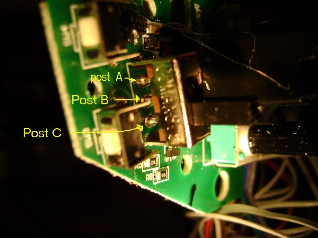 Rear 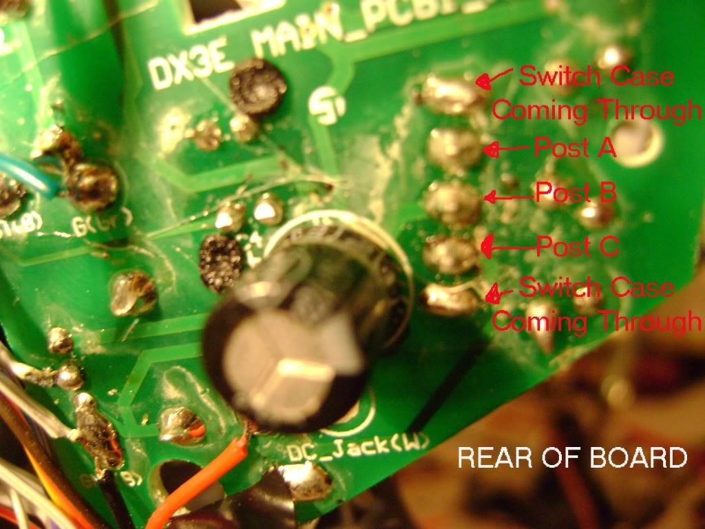 |
|
| |
|
01-13-2011, 10:19 PM
| #4 |
| I wanna be Dave Join Date: Nov 2010 Location: 07456 N. NJ USofA
Posts: 8,314
|
For me, looks like B & C (from the front side) are a charging port, leading me to believe A & C are what you need to connect to a new switch. |
|
| |
|
01-14-2011, 03:53 AM
| #5 |
| Quarry Creeper Join Date: Jan 2010 Location: USA
Posts: 402
|
The original switch shorts A & B to turn the power on. When it is off B & C are shorted together. I would hook your external switch to A & B.
|
|
| |
|
01-14-2011, 03:43 PM
| #6 |
| Quarry Creeper Join Date: Jul 2008 Location: Erin, Ontario, CANADA
Posts: 471
|
OK, what we are looking at is a single pole, double throw switch. A very cheap and crappy one at that..... The centre pin of the switch is the common and my guess is that it goes straight to battery +ve. My further guess is that moving the switch one way connects the power (battery) to the electronics, and moving it the other way connects the battery +ve to the charging jack. You can prove my theory by connecting a voltmeter between the battery -ve and the center pin......it should read the battery voltage. Then you can prove how the connections on the switch work using an ohmmeter between the various switch pins and even the charging jack (note batteries OUT of the transmitter when you do this check.) Once you know which Pin (A or C) is the "electronics" you can parallel another on/off (single pole, single throw aka SPST) switch across that pin and the centre pin. The only thing you will have to watch out for is that you don't have the original switch set to "charge" and the new switch set to "transmitter ON" with your charger connected. This would have a fair chance of letting the magic smoke out of your transmitter. Hope this helps, Narly1 |
|
| |
|
01-14-2011, 06:04 PM
| #7 |
| Quarry Creeper Join Date: Mar 2008 Location: Columbus OH
Posts: 234
|
Thanx guys problem solved.
|
|
| |
|
| |


 Linear Mode


