| |
 10-17-2006, 08:15 AM
| #1 |
| Rock Crawler Join Date: May 2006 Location: United Kingdom,Scarborough
Posts: 563
|
hi can some1 show me some pictures or tell me how to wire a matrix 65t lathe motor. thanx for any information given james |

|  |
| Sponsored Links | |
| | |
|
10-17-2006, 08:57 AM
| #2 |
| RCC Addict Join Date: May 2006 Location: In England, looking for the threadlock...
Posts: 1,150
| 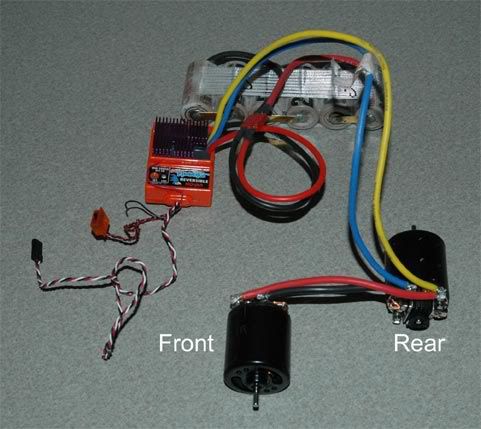 I'm using this at the mo'. Cheers 8-) Last edited by 4link4eva; 11-16-2006 at 10:43 AM. |
|
| |
|
10-17-2006, 02:04 PM
| #3 |
| Quarry Creeper  Join Date: Dec 2005 Location: United Kingdom
Posts: 234
|
Many thanks for the reply . What moondust1950 {my son} is looking for, and if I am honest me also, is help on where to solder the connecting wires from the esc. At the end of the motor appear to be six areas that will accept soldered wires. Four in the "corners" and two in the centre, top and bottom. Do we connect the wires that are on the original TXT 1 motor to the connections that are in the centre both top and bottom. If we do can you kindly inform us what the connections in the corners are for. I believe they may be for cappacitors but I am not sure. I have spent around two hours using the search button and also searching the internet but have been unable to find the information. Any assistance will be most helpfull. Thankyou |
|
| |
|
10-17-2006, 02:20 PM
| #4 |
| I wanna be Dave Join Date: May 2005 Location: Anchorage, Alaska
Posts: 2,048
|
If I read it right, the four posts should be the solder tabs for the wires. 2 are positive and 2 are negative. Each pair on each side is comprised of a neg tab and a pos tab. They should be marked as to which is which but if you hook it up backwards, it won't hurt anything. If you have a photo you can post, that would help. |
|
| |
|
10-17-2006, 02:25 PM
| #5 |
| Pebble Pounder Join Date: Oct 2006 Location: rochester (detroit area)
Posts: 116
|
if i understand what you're asking correctly, you're looking at 2 sets of + and - on the motor. on each side of the can. you'll only need to solder the ESC leads to one side... one (+) and one (-) and if you look at the motor from the top, if it's a lathe motor (or any motor), it will be marked with a (+) on one side. the tab in the center is for the capacitors... which you'll solder 3 of them to the other side (opposite your ESC solder side). one capacitor goes from the (+) to the (-), a second goes from the (+) to the center tab, and the 3rd goes from the center tab to the (-). again - these will go only on one side of each motor - the side opposite opposite of your ESC wires. edit: i was beat to the answer, but hopefully my exp. will help with the capacitors you'll need (lathe motors don't come with them as, well, they're meant to run lathes and not connected to an ESC or cause radio interference). you'll need 3 capacitors for each motor too. |
|
| |
|
10-17-2006, 02:35 PM
| #6 |
| Quarry Creeper Join Date: Dec 2005 Location: United Kingdom
Posts: 234
|
WoooHooooo. Brilliant. Bloody Brilliant. Boy this is like christmas from my youth. It is great when you spend ages trying to find something out and then someone gives you the answer in minutes. Thankyou very much guys |
|
| |
|
11-15-2006, 09:29 PM
| #7 |
| Newbie Join Date: Feb 2006 Location: Huntington
Posts: 1
|
can yuo tell me what size capacitors are required, thanx. |
|
| |
|
11-15-2006, 11:54 PM
| #8 |
| Quarry Creeper Join Date: Dec 2005 Location: United Kingdom
Posts: 234
|
We used the capacitors that where supplied. If you type capacitors in the search box you will go throught the threads. I know in one of them it does give the size required as I have read it previously.
|
|
| |
|
11-16-2006, 10:50 AM
| #9 |
| RCC Addict Join Date: May 2006 Location: In England, looking for the threadlock...
Posts: 1,150
|
Tronk, when you have the capacitors on, tell us what the differences are, I'm still following this thread.  |
|
| |
|
11-16-2006, 10:53 AM
| #10 |
| Rock Crawler Join Date: May 2006 Location: United Kingdom,Scarborough
Posts: 563
|
Hi am tronks son. i am running the caps on my 65t lathe motor. There wasn't really much difference the glitching stopped a little and the range on my transmitter has in proved |
|
| |
 |
| |


 Linear Mode


