| |
| |||||||
 |
| | LinkBack | Thread Tools | Display Modes |
 06-18-2008, 03:33 PM
| #1 | |
| varcor.org   Join Date: Aug 2005 Location: 757
Posts: 1,073
|
Hey Robb, Can you post pics of your dig setup (4wd, free, locked)? I suck at understanding wiring diagrams. Quote:
| |

|  |
| Sponsored Links | |
| | |
|
06-18-2008, 03:41 PM
| #2 |
| Im Brandon   Join Date: Feb 2005 Location: Colfax, CA
Posts: 8,156
|
Im working on a diagram now for someone else, I will post it up here as well  EDIT: Added diagram. I think this is correct, if its not let me know I will fix it. Red wires: Positive White wires: Negative. Last edited by Brandon; 06-18-2008 at 04:04 PM. |
|
| |
|
06-18-2008, 03:46 PM
| #3 |
| I wanna be Dave Join Date: May 2005 Location: CITY of CHAMPIONS!!
Posts: 2,086
|
here are pics of mine if that helps you. 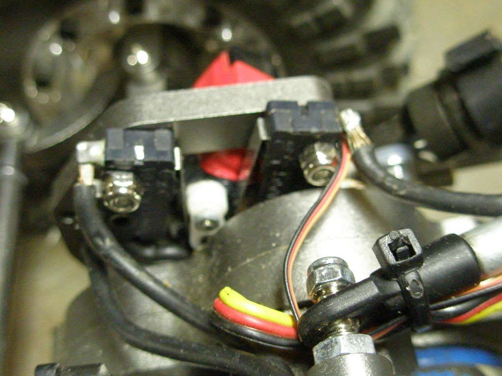 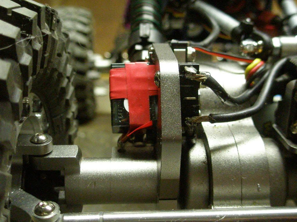  mine are set up to free wheel though, they do not dead short the motors. |
|
| |
|
06-18-2008, 04:07 PM
| #4 |
| Im Brandon Join Date: Feb 2005 Location: Colfax, CA
Posts: 8,156
|
For Front/Rear dig use Badd's diagram Note: Removing either red 16ga wire will eliminate the locked axle and allow them to freewheel. |
|
| |
|
06-18-2008, 04:13 PM
| #5 |
| Im Brandon Join Date: Feb 2005 Location: Colfax, CA
Posts: 8,156
|
Here is something I am working on... This wiring diagram allows you to have front and rear dig, as well as a third switch to disable the lock on the rear axle and allow it to freewheel. This is only possible with a 4ch transmitter though Or in my case I will be simply installing a 2 position switch on the chassis that I can manually use before I start a course if I feel that free wheel or dig will be more beneficial. |
|
| |
|
06-18-2008, 04:15 PM
| #6 |
| Im Brandon Join Date: Feb 2005 Location: Colfax, CA
Posts: 8,156
|
Here is Bonus Lines micro servo and radio shack switch setup for a better idea of what I posted in the diagrams above.
|
|
| |
|
06-18-2008, 04:22 PM
| #7 |
| Quarry Creeper Join Date: Feb 2008 Location: no more lockers
Posts: 400
|
i followed badd's wiring diagram , works great
|
|
| |
|
06-18-2008, 04:28 PM
| #8 |
| I wanna be Dave  Join Date: Dec 2005 Location: Happiness is a warm AK.
Posts: 12,563
|
It's awesome to see how far this has come from the OG D.U.D. set I built using some crap I had lying around the shop! By Berg is only waiting on a few components. When everything comes together, I'll be using this DIG set up as well. Thanks for all the diagrams for the duel set ups! |
|
| |
|
06-18-2008, 09:31 PM
| #9 |
| RCC Addict Join Date: Aug 2005 Location: VARCOR
Posts: 1,826
|
Lots of great info here!!! This is how mine is set up based on the diagram above. This pic shows the switch positions in relation to the diagram:  Randy, I doubt actual pics of my setup would do you any good, because all the wires are wrapped and heatshrinked, etc. I even took a look at it and it made no sense to me!  The great thing I love about this fully electrical DIG is that it can be bypassed if a problem occurs. It isn't shown in this pic, but there is enough length in the wiring to the rear motor that if any problem occurs with the servo or the switches, the deans plugs to-n-from the switches can be plugged into each other, bypassing the DIG altogether, and allowing me to continue to run. |
|
| |
|
06-18-2008, 09:33 PM
| #10 |
| I wanna be Dave Join Date: May 2005 Location: CITY of CHAMPIONS!!
Posts: 2,086
|
great idea on the bypass. |
|
| |
|
06-19-2008, 04:54 AM
| #11 |
| varcor.org Join Date: Aug 2005 Location: 757
Posts: 1,073
|
thanks guys... that helps alot...
|
|
| |
|
06-19-2008, 12:32 PM
| #12 |
| Quarry Creeper Join Date: Dec 2007 Location: Chester VA
Posts: 426
|
Dangit Robb, that is exactly how I am mounting my switches. I posted a pic of the part numbers in some thread here and got shot down for the roller switches meh, anyway I havent figured out how to make the roller trigger wheel for the servo, any info on that youd like to share ole buddy ole pal? it looks like you just ground dibbits in a round servo horn?... |
|
| |
|
06-19-2008, 01:07 PM
| #13 |
| Rock Crawler Join Date: Mar 2008 Location: Arizona
Posts: 578
|
Now I need a 4 ch with 2 3p switches for ch3 and 4 |
|
| |
|
06-19-2008, 07:37 PM
| #14 | |
| RCC Addict Join Date: Aug 2005 Location: VARCOR
Posts: 1,826
| Quote:
Roller switches work great in this scenario. Only problem with them, is that only work one way and will not work if you try to close them with a single horn from the opposite direction that the switch wants to close. A wide-a$$ horn that keeps the arm from fully extending will eliminate the play of the arm, and allow the switches to operate correctly depending whether they are riding on the base of the horn, or in a groove on the horn. Base of horn = closed, groove = open. | |
|
| |
|
06-19-2008, 08:22 PM
| #15 |
| I wanna be Dave Join Date: May 2005 Location: CITY of CHAMPIONS!!
Posts: 2,086
|
that is why i use the ones with just the arm no roller. |
|
| |
|
06-19-2008, 08:43 PM
| #16 | |
| RCC Addict Join Date: Aug 2005 Location: VARCOR
Posts: 1,826
| Quote:
And with or without a roller, the same problem would exist. and bending the arm doesn't count as an answer | |
|
| |
|
06-19-2008, 08:50 PM
| #17 | |
| I wanna be Dave Join Date: May 2005 Location: CITY of CHAMPIONS!!
Posts: 2,086
| Quote:
| |
|
| |
|
06-19-2008, 09:14 PM
| #18 | |
| varcor.org Join Date: Aug 2005 Location: 757
Posts: 1,073
| Quote:
| |
|
| |
|
06-19-2008, 09:17 PM
| #19 |
| RCC Addict Join Date: Feb 2005 Location: Minneapolis
Posts: 1,496
|
I like the pic on the bottom shown in the thread dig setup and wiring? here is the pic  but the switches look to be activated in the exact way that Robb is saying they will not work (If I am viewing it right.....which would not surprise me if I am not). Just curious, as I like the idea of having everything in one small box. Last edited by wrightcs77; 06-19-2008 at 09:22 PM. |
|
| |
|
06-19-2008, 09:19 PM
| #20 | |
| RCC Addict Join Date: Aug 2005 Location: VARCOR
Posts: 1,826
| Quote:
| |
|
| |
|
 LinkBacks (?)
LinkBack to this Thread: http://www.rccrawler.com/forum/enroute-berg/124079-robb-pics-your-dig-setup.html | ||||
| Posted By | For | Type | Date | |
| ÎÒÒ²À´Ì¸Ë«µç»úÅÀÅÀµÄ¶Ï´«£¨¸½´óÁ¿Í¼ÎÄ£© - ÅÊÅÀÀÖÔ° - Ò£¿ØÃÔÄ£ÐÍÂÛ̳|RCFans.com - Powered by Discuz! | This thread | Refback | 10-05-2011 08:30 AM | |
| |


 Linear Mode


