| |
| |||||||
 |
| | LinkBack | Thread Tools | Display Modes |
 12-31-2005, 08:04 AM
| #1 |
| Pebble Pounder Join Date: Nov 2005 Location: Evansville
Posts: 137
|  Someone asked for some tire photos... From left to Right -Narrowed Wheel, shallow lugs and sidewall lugs removed (my personal fav) -Standard Wheel, shallow lugs and sidewall luges removed (insane sidewall flex) -Standard Wheel, Every other entire treadbar and sidewall lug removed (Eh, its alright) -Standard Wheel, mod of previous, every other lug again removed, way too much flex not enough tread.  I have since made aluminum skids from cut up cans glued to the plastic, its been used some  Rear Axle Cover  Rear Axle Cover Removed  First Look Inside  High/Low Range selector, notice the small spring by the pivot? This allows the gears on the selector to be pushed past the gear drum until both axles are engaged, the tension is then released and the gears re-mesh. Brilliant!  Passenger Side "Gen 2" axle shaft, wheel bearing, and drive coupler. This white coupler is a common weak point.   Driver Side axle shaft, it engages the actual driving axle by a teeny tiny pin, you see inside the shaft how it engages.  Drive Motor of course  Drive Coupler on left, HIGH/LOW Planetary, HIGH/LOW slider, Drive motor planetary  HIGH/LOW Gear assembly cover  HIGH/LOW Motor setup       This white collar drive coupler is a weak link, the "Gen 3" or upgraded chassis as people know, have metal collars. As you can see at this point my collar is already slightly deformed, you are better off filling this with JB weld and reassembling it from the get-go.  These four small balls are all that are used to connect the drive planetary to the HIGH/LOW Range planetary assembly, slap some grease on these and grease the gear boxes and things work much smoother and quieter.  A Small pin on the far right side of the metal shaft must be removed, a pair of sidecuts used to wedge and wiggle made short work of its press fit, don't loose this pin as it actually drives the driverside tire.  The inner workings of the HIGH/LOW Planetary, the blue gear is a direct drive portion while the white ball/shaft assembly gets driven further into it in LOW and then drives the small 3 gear planetary.  HIGH Range  Inside the HIGH/LOW Gearbox  LOW Range Gears  The drive motor planetary assembly  LOW Again  Steer axle cover  Steer Axle First Look  Passenger Side Knuckle  These are press fit into the knuckle bearings, the knuckle bearings are pressed in as well.  This pin must be removed from the pitman arm in order to pull the steering box  Steering box pulled from steer axle  Cover removed from steering box  As you can see, LEFT to RIGHT. Steering position sensor, Pitman arm, Spacer, Steering gearbox (3 stage planetary!), Steering motor on bottom.        Sorry, removed the drive motor cover before taking a photo of it or the planetary assembly, almost identical to the rear assembly. Last edited by Mutt; 01-02-2006 at 04:08 PM. |

|  |
| Sponsored Links | |
| | |
|
12-31-2005, 08:15 AM
| #2 |
| Pebble Pounder Join Date: Aug 2005 Location: VT Burlinton
Posts: 118
|
We need a FAQ or make this a sticky. Stu |
|
| |
|
12-31-2005, 08:56 AM
| #3 |
| Pebble Pounder Join Date: Nov 2005 Location: Evansville
Posts: 137
|
I figured out, in my mind, how to use the steering assemblies triple geared planetary system to make an ultra low gearbox. This would in theory allow for a high range lower that the current low and a low way lower that the current low range...Which is how this things should have been built in the first place. |
|
| |
|
12-31-2005, 09:01 AM
| #4 |
| Pebble Pounder Join Date: Dec 2005 Location: Price, UT
Posts: 108
|
imagine the run time on the battery alone if it works
|
|
| |
|
12-31-2005, 09:10 AM
| #5 |
| Pebble Pounder Join Date: Nov 2005 Location: Evansville
Posts: 137
|
I lightly greased all my gearboxes with Mobil1 Synthetic Wheelbearing grease...Wow, the gearboxes are super quiet now, I also forced grease into the "wheel" bearings as these bearings are NON-SEALED units, meaning if you dive into water alot, these bearings will be ruined. So i greased the area around them as well to help prevent water intrusion and pooling. I greased any moving part, such as the knuckle's "kingpins". I also found that leaving the "tierod" cover off is a bad thing, it allows wayyy too much deflection and leads to a bent tierod. I have since run a screw through the front cover to keep the tierod from bowing upward. I also did not lubricate, but cleaned the high/low motor and gear assembly. I noticed lithium grease thrown about inside the cover and on the motor pulley and belt. Yes I am still using stock belts not o-rings with no slippage, just sanding and chemical cleaning has worked wonders. Last edited by Mutt; 12-31-2005 at 09:14 AM. |
|
| |
|
12-31-2005, 09:35 AM
| #6 |
| Quarry Creeper Join Date: Dec 2005 Location: Mechanicsville, VA
Posts: 464
|
Nice pics. I pulled my rear apart this morning before work. My "t-case" gears are stripped so I'm gonna permently lock mine into low, which is 99% of what I use anyway. Keep us updated on the gear idea you mentioned. Once I get more time to look at mine I may try to do something simular. I was also thinking of a way to possible get rid of belt drive system and either go with some type of metal gear set-up or chain-drive deal. I'm gonna look at mine a little closer later and anything that's plastic that think I can replace with metal I'm going to. Could you get better pics of the steering set-up... |
|
| |
|
01-05-2006, 03:04 PM
| #7 |
| Pebble Pounder Join Date: Dec 2005 Location: Byron
Posts: 112
|
how'd you remove the front pins that hold the spindles in? ( the front hubs,, the pins that hold them in)
|
|
| |
|
01-06-2006, 11:52 PM
| #8 |
| Newbie Join Date: Dec 2005 Location: Downey
Posts: 6
|
Thanks for the breakdown. It made it easy for this newbie to replace a axle pin using a piece of a allen key. |
|
| |
|
01-30-2006, 09:49 AM
| #9 |
| Newbie Join Date: Jan 2006 Location: Knoxville
Posts: 30
|
thx for the pics man. Helped me in getting the steering servo out of the front diff assembly.
|
|
| |
|
02-02-2006, 10:21 PM
| #10 | |
| Rock Stacker Join Date: May 2005 Location: hills
Posts: 75
|
have you tried this yet mutt?sounds like a good idea Quote:
| |
|
| |
|
02-02-2006, 10:39 PM
| #11 | |
| Quarry Creeper Join Date: Aug 2005 Location: Crawlorado
Posts: 333
| Quote:
they are geared to low already... you have no wheel speed it sucks. even lower would make them crawl worse | |
|
| |
|
02-03-2006, 03:12 PM
| #12 | |
| Rock Stacker Join Date: Jan 2006 Location: On the rocks...
Posts: 66
| Quote:
Ever tried to stop a glacier? Oh, BTW, Mutt, THANKS for posting this thread and taking the time to shoot all those pictures, great job. Last edited by vlmarshall; 02-04-2006 at 08:20 AM. | |
|
| |
|
02-18-2006, 02:34 PM
| #13 | |
| Newbie Join Date: Aug 2005 Location: Granby
Posts: 22
| Quote:
the only time i wish i could get a little wheel speed is right when its about to roll, so i could save it by throwing it in reverse | |
|
| |
|
03-13-2006, 04:21 PM
| #14 |
| Quarry Creeper  Join Date: Aug 2004 Location: Southwestern PA
Posts: 259
|
Thanks for the pics. They also helped me replace a snapped drive pin on the back axle of my 1Gen rig. Although instead of the allen key, I actually used an e-clip style Tamiya Juggernaut 2 drive shaft U-joint pin I found rolling around my workbench. I just had to grind it a little shorter to fit inside the stub axle sleeve...
|
|
| |
|
03-22-2006, 01:13 PM
| #15 |
| Diggin' the new SCX10 II!  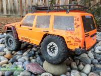 Join Date: Mar 2004 Location: Norcal
Posts: 11,402
|
We have to many stickies in this forum, I have un stuck this and added a link to this in the The Ultimate Nylint mod guide - Links to every modification! |
|
| |
|
06-22-2006, 03:02 PM
| #16 |
| Newbie Join Date: Apr 2006 Location: Tucson
Posts: 9
|
I have just pulled mine apart, and for the love of money I can not figure out what part of the shaft (steel) is attached to the gears. I have tried to super glue it in several differant places, with no luck. I have it setting in the shed right now because if I get it back out and try it one more time it might end up as a boat ancore. I can get a new axle for it threw nylint but there is nothing wrong with the one that I have. (other than it dont work) I have taken it apart to put the greese in the gears like posted and now I cant get it back together right. Any help would be great. Thanks in advance Marc |
|
| |
|
06-22-2006, 06:59 PM
| #17 |
| Rock Crawler  Join Date: May 2006 Location: Burrillville, RI
Posts: 778
|
can you post some pics so we can tell you where your assembly problem is?
|
|
| |
|
07-27-2006, 08:31 PM
| #18 | |
| Newbie Join Date: Apr 2006 Location: Tucson
Posts: 9
|  Quote:
I need to know what gear is actually conected to the drive shaft. I have super glued, JB Welded, and even drilled and pinned with no luck. My guess is I am doing all this to the wrong gear. I have been doing this to the out side gear on the passanger side. The very last photo will show you where I have been doing all this labor to. I am starting to thing that it might be a lost cause. 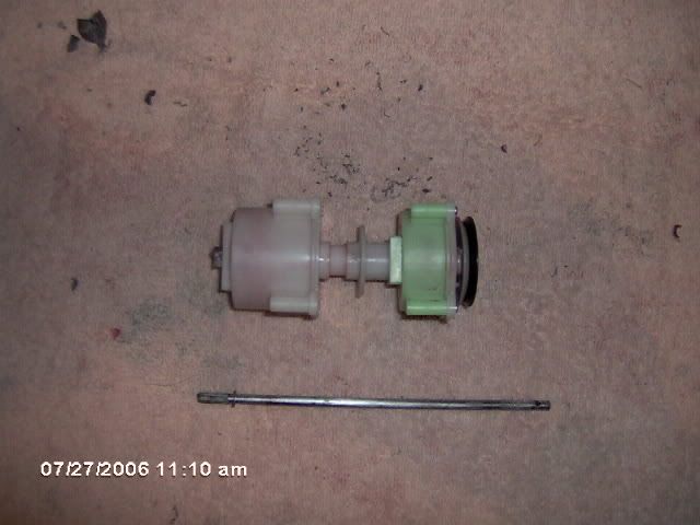 Now in this photo I am thinking that the greenish colored gear is the one that should be "glued to the axle shaft" 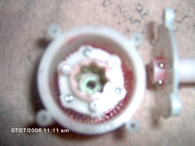 and as you might be ably to see, This is the one that I have been trying to get to atach to the shaft. You can kind of see the bugered up end. It is however still usable but just looks bad. Which one do you think needs to be attached to the shaft? 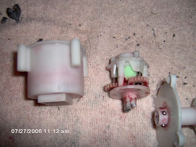 That is the gear I have been glueing and welding and even drilled and pinned. after all this I think its the wrong gear I should be working on. Sorry for the bad quality of the photo. thanks again Marc | |
|
| |
|
| |


 Linear Mode


