| |
| |||||||
 |
| | LinkBack | Thread Tools | Display Modes |
 01-27-2006, 01:10 PM
| #1 |
| Powered by Awesome   Join Date: Sep 2004 Location: Parker, Colorado
Posts: 3,622
|
Let me run this by you to see what everyone is using.... ok Throughout a suspensions cycle it has an arc of rotation example: illistrated in green 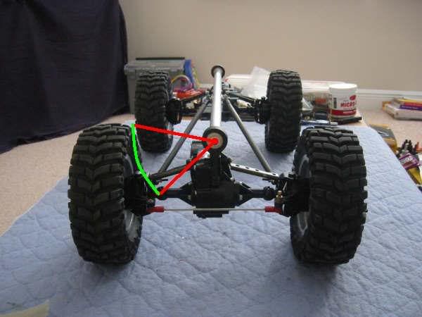 Here is where the mounting options come in. You can mount the shock from 90 degrees to 0 in accordance with the arc of travel, again see below: 90 Degrees Light Baby Blue 45 Degrees Purple/pinkish 0 Degrees Red 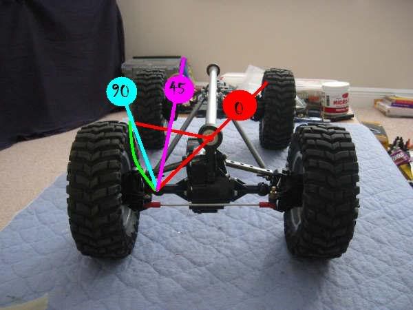 For Rock crawling what has everyone found to be the most effective degree of mounting. keep in ming that 90 degrees with a 4" travel shock gives 4" of compression with 100% effectiveness 45 degrees with a 4" travel shock gives 6" of compression with 50% effectiveness 0 degrees with a 4" travel shock gives no compression with 0% effectiveness brain teaser for the day Last edited by TwistedXT; 01-27-2006 at 01:15 PM. |

|  |
| Sponsored Links | |
| | |
|
01-27-2006, 01:24 PM
| #2 |
| I wanna be Dave Join Date: Jun 2004 Location: San Jose
Posts: 5,207
|
I've got a brainteaser. Where are you going to find a 4" travel RC shock?
|
|
| |
|
01-27-2006, 01:27 PM
| #3 |
| Pebble Pounder Join Date: Sep 2005 Location: Bellevue
Posts: 122
|
I dont have a stick, but has anyone tried mounting a spring around the "stick" part attached at one end to the "stick" and the other end to the rod end coming out of the axle (spiralling around the stick). You would probably need a different type of spring but this way the spring would load/unload 100" effectively and cut down weight. Maybe the type of spring in a servo saver... Only problem then is shocks. Dont even know if its work the hassle, just a thought. Sorry i cant explain the idea better, hope you can understand what im saying. To answer your questian, why not make a variable point mount first, to see what you like. Last edited by DUIdirk; 01-27-2006 at 01:36 PM. Reason: to add info |
|
| |
|
01-27-2006, 01:37 PM
| #4 |
| Rock Crawler Join Date: Nov 2005 Location: Oak Ridge
Posts: 590
|
Like the little spring in a clothespin?
|
|
| |
|
01-27-2006, 01:38 PM
| #5 | |
| Powered by Awesome Join Date: Sep 2004 Location: Parker, Colorado
Posts: 3,622
| Quote:
Last edited by TwistedXT; 01-27-2006 at 01:43 PM. | |
|
| |
|
01-27-2006, 01:49 PM
| #6 |
| Colt Python/SR9c 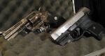 Join Date: Feb 2004 Location: out in the shop, reloading ammo!
Posts: 8,626
|
but your degrees are off..if you mounted it at your said "45* " it would actually be close to a 90* setup..actually around 80*.. on 1:1 shocks, if you lay them at a 45* angle. you get 1" of travel for every 1/2" of shock shaft. besides, if you mount it at your 90* you would rub your tires |
|
| |
|
01-27-2006, 02:37 PM
| #7 |
| Pebble Pounder Join Date: Sep 2005 Location: Bellevue
Posts: 122
|
Right, i think the angles are set up wrong too. It think the way you should think about it is: 100% effectiveness would be acheived when the shock is positioned tangent to the radius of the arc where the line drawn for the mounting bracket intersects the arc. No?
|
|
| |
|
01-27-2006, 02:41 PM
| #8 |
| Powered by Awesome Join Date: Sep 2004 Location: Parker, Colorado
Posts: 3,622
|
i labeled that position as 90 degrees (light blue) because i am using the flat mounting point that follows the arc a zero setting (labeled in red). you are correct though, in fact if you look at the pic, the 90 degree setting does infact intersect the arc of the cycle.
|
|
| |
|
01-27-2006, 02:48 PM
| #9 |
| Rock Stacker Join Date: Dec 2004
Posts: 54
|
you also need to account for the distance your shock is from the center of the axle. the farther out, the stronger the force of the shock will exert; the farther toward center, the less force the shock will be able to exert. of course, this also affects the amount of travel you will see at each wheel. so to answer your question, there are just too many variables to ask a question such as yours, and expect any kind of consistancy in answers. personally, i've found a position that seems to work on my txt based crawler and still use the stock shocks and springs. i get almost 0 torque twist, and still get great articulation. of course it took a long time find a position that works so good with these shocks. |
|
| |
|
01-27-2006, 03:14 PM
| #10 |
| Powered by Awesome Join Date: Sep 2004 Location: Parker, Colorado
Posts: 3,622
|
thats something i have learned to... you just have to mess with it. On previous rigs, i have tried to put numbers to it but even though it seems to work out on papaer, it still handles like a turd. |
|
| |
|
01-27-2006, 03:18 PM
| #11 |
| Colt Python/SR9c Join Date: Feb 2004 Location: out in the shop, reloading ammo!
Posts: 8,626
|
or you just don't worry about all the math and trig stuff and just slap on the shocks and move them til your happy but your green arrow showing the arc movement wouldn't even be right to start with. So your screwed from the get go |
|
| |
|
01-27-2006, 03:19 PM
| #12 |
| owner, Holmes Hobbies LLC  Join Date: Nov 2004 Location: Volt up! Gear down!
Posts: 20,290
|
i set my stick up to fully compress the shock at a 90 degree angle. i.e. when the shock is fully compressed the angle of the backbone shock mount is 90 degrees from the shock body. This gives me a true rising rate suspention. I dont care about the rest as long as my articulation is right. |
|
| |
|
01-27-2006, 04:34 PM
| #13 |
| Pebble Pounder Join Date: Sep 2005 Location: Bellevue
Posts: 122
|
Twisted: Not that it has much to do with the progress of this thread, but I am failing to see what is wrong with the green arc movement arrow? A point that is a given distance from the center of a circle, should stay the same distance from the center of the circle if rotated about the center. So long as the rest of the structure is static, such as the axle. Unless those links are messing with the 2D rotation and adding a Z component of movement, which should be pretty small. Maybe you can help me out? |
|
| |
|
01-27-2006, 07:17 PM
| #14 |
| Colt Python/SR9c Join Date: Feb 2004 Location: out in the shop, reloading ammo!
Posts: 8,626
|
Umm for one speak english when a truck is sitting at ride height and you compress one side. how many axles have you seen go straight up and out farther as his green line is? The way that is setup, it would slightly come up but into the truck. It wouldn't go out any farther as he has the green line doing. So in turn, his 90* mark would be shoving itsself into the shock before it is barely compressed.. It's not all the trig and whatever physics needed. What is needed is just a little bit of common sense |
|
| |
|
01-27-2006, 09:30 PM
| #15 |
| I wanna be Dave Join Date: Jan 2004 Location: Austin Texas
Posts: 3,866
|
Hrm, this is interesting, and has more to do with geometry than physics. I'm not the best with suspension design so please feel free to correct me if I'm wrong It's very hard to draw the rotation of an axle because you're basically dealing with one point (the bottom of the tire) rotating around another point (the roll center). Ideally the picture would need to be perfectly level with the truck directly in front of it to show this so the picture I did is slightly inaccurate but it should give you a good starting point.  The white circle and square represent the movement of the axle. The red line is a tangent of the circle which gave me a good indication of where the shock should be placed. The shock should be parallel to this line and is represented by the dark green line. |
|
| |
|
01-27-2006, 09:46 PM
| #16 |
| RCC Addict Join Date: Jan 2005 Location: Green River Kentucky
Posts: 1,067
|
This and ilrcrc's math on the other post make my head hurt.Althouth I do belive highmark is correct.
|
|
| |
|
01-27-2006, 11:00 PM
| #17 |
| Pebble Pounder Join Date: Sep 2005 Location: Bellevue
Posts: 122
|
Twisted: the stick isnt like a normal truck, the axle basically rotates around the backbone when articulating. High described it well with the roll center stuck at one point. If traveling around the stick, any point on the axle should never get closer or further from the backbone of the stick. High: I agree. thats what i was trying to say with one of my posts above. No mater if the circle is big or small, the tangent to each circle should parallel each other anyway. Its kinda hard to see on this photo given the camera angle, but yeah, i agree. It would be easy anyway to make it adjustable. Plus with so many different spring rates for shocks, you can make adjustments there too. |
|
| |
|
01-28-2006, 07:15 AM
| #18 | |
| I wanna be Dave  Join Date: Apr 2005 Location: Vegas
Posts: 7,172
| Quote:
| |
|
| |
|
| |


 Linear Mode


