| |
 12-06-2011, 01:47 AM
| #21 | |
| Quarry Creeper Join Date: Apr 2011 Location: Waimanalo, Hawaii \m/
Posts: 426
| Quote:
| |

|  |
| Sponsored Links | |
| | |
|
12-06-2011, 06:29 AM
| #22 |
| I wanna be Dave  Join Date: Jan 2006 Location: Iowa, the antirecreation state!
Posts: 2,227
|
Here maybe: Szczerba's Trophy Truck Build.. With Videos |
|
| |
|
12-06-2011, 07:42 PM
| #23 |
| RCC Addict Join Date: Jul 2008 Location: Sin City
Posts: 1,332
|
Lots of goodies this time. Got a new chassis cut out, figured out the battery mounting, cut the other swing arm, and got everything swapped out. Fits a body much better now tho i still dont know what body it will be. First a couple shots of the work in progress since someone asked about the laser previously.  [/URL] [/URL]DSC_0015[/URL] by phukyr[/URL], on Flickr  [/URL] [/URL]DSC_0016[/URL] by phukyr[/URL], on Flickr  [/URL] [/URL]DSC_0018[/URL] by phukyr[/URL], on Flickr 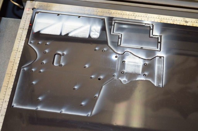 [/URL] [/URL]The little red light is just the diode pointer. Useful if you need to calibrate the mirrors or make a test pass without cutting to make sure you are lined up with the edges of the material or recutting something. DSC_0019[/URL] by phukyr[/URL], on Flickr All the parts are cut. Now to walk through the snow to the RC hut. LOL  [/URL] [/URL]DSC_0020[/URL] by phukyr[/URL], on Flickr Side by shot once i got the stuff pulled off the first chassis. The new one is wider with the nose cut down a bit. The bumper, front end, will bolt to the shortened nose once it done. Its a bit wider to accomidate the battery mount on the passenger side and it will be much closer to the edge of the body so it will hopefully keep the insides a little cleaner.  [/URL] [/URL]DSC_0021[/URL] by phukyr[/URL], on Flickr And with everything all mounted up. You can see the battery mount on the passenger side. 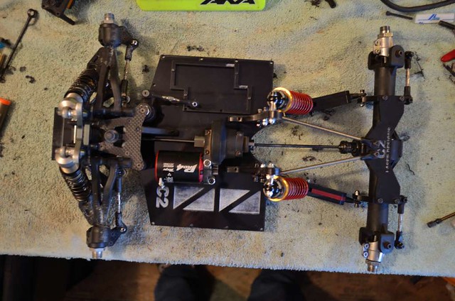 [/URL] [/URL]DSC_0022[/URL] by phukyr[/URL], on Flickr Didnt paint the other swing arm. May dye some delrin later but for now i wanted to check functionality.  [/URL] [/URL]DSC_0024[/URL] by phukyr[/URL], on Flickr Where the front of the upper rails will tie into the chassis and make the bumper mount. 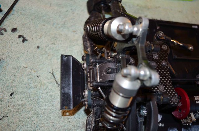 [/URL] [/URL]DSC_0025[/URL] by phukyr[/URL], on Flickr Closeup of the battery mount. Im going to either make a strap across the top of them or notch the underside and use velcro. Im not sure yet. I have some carbon firber stock so that might be it.  [/URL] [/URL]DSC_0026[/URL] by phukyr[/URL], on Flickr  [/URL] [/URL]DSC_0027[/URL] by phukyr[/URL], on Flickr You can see how much closer the motor is to the steering rack now from moving the center diff forward. There will be a spar of delrin still wedged in there as a part of the upper rails when its done.  [/URL] [/URL]DSC_0028[/URL] by phukyr[/URL], on Flickr And just a couple random shots thrown in there cause someone asked for more pictures, lol. 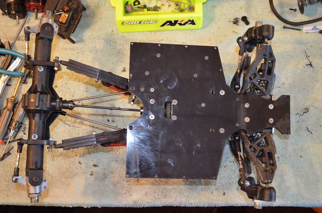 [/URL] [/URL]DSC_0029[/URL] by phukyr[/URL], on Flickr  [/URL] [/URL]DSC_0030[/URL] by phukyr[/URL], on Flickr 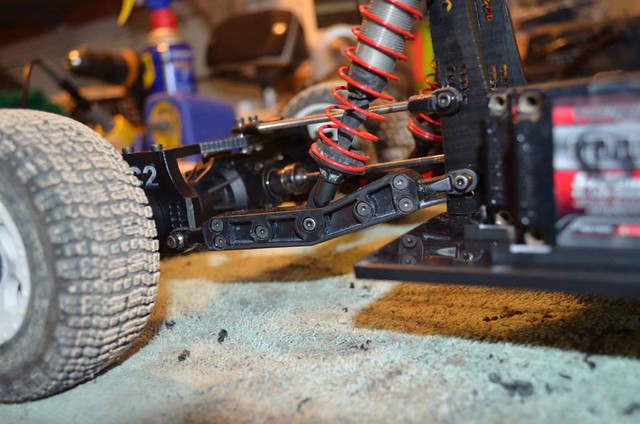 [/URL] [/URL]DSC_0031[/URL] by phukyr[/URL], on Flickr And a couple body test shots one from my old losi SCTE 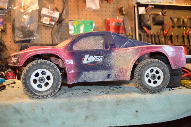 [/URL] [/URL]DSC_0036[/URL] by phukyr[/URL], on Flickr and one with one of my old durango DESC410 bodies.  [/URL] [/URL]DSC_0038[/URL] by phukyr[/URL], on Flickr Much happier with the body fitment. Thats all i got for now. Should be able to start designing the upper rails tomorrow.  |
|
| |
|
12-07-2011, 10:50 AM
| #24 |
| I wanna be Dave Join Date: Jan 2006 Location: Iowa, the antirecreation state!
Posts: 2,227
|
I'm jelous. How do you justify the lazer? Of is it your business? Nice stuff mang |
|
| |
|
12-07-2011, 11:44 AM
| #25 | |
| RCC Addict Join Date: Jul 2008 Location: Sin City
Posts: 1,332
| Quote:
| |
|
| |
|
12-12-2011, 10:00 PM
| #26 |
| RCC Addict Join Date: Jul 2008 Location: Sin City
Posts: 1,332
|
Taken a few days to get through this part, hence, no recent updates. Now time for some fun, the front end side plates and shock tower-thing. First i made the replacement piece for the front shock tower. Im not using the stock piece but the upper links mount into it and i figured, since i had to make it anyway, it would be a good place to tie into the vertical plates and add strength. 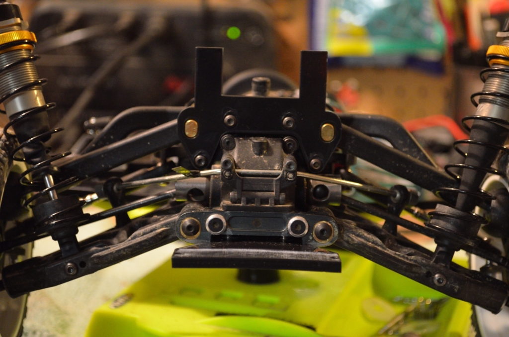 [/URL] [/URL]DSC_0062[/URL] by phukyr[/URL], on Flickr Now on to the side plates. First, the process. Make a cardboard template with a half of a case of diet coke and a ruler. Then its cut out of cheap 1/8 acrylic, this makes sure everything lines up with hard edges and the acrylic is cheap junk that was laying around so no loss. Then the final version is cut out of 3/16 delrin. This is just the cheapest way to work out fitment since i didnt model the whole truck in 3d im actually measuring, cutting, measuring, cutting, etc. I asked santa for autocad for xmas, i hope he hooks me up.  [/URL] [/URL]DSC_0063[/URL] by phukyr[/URL], on Flickr After 3 mock up pieces it BETTER fit right the first time, lol. It did though i need to dig around my drill bits some more and maybe tap these holes. You can see where it white lined from stretching the delrin. One thing im really happy with on this design is i can change pinion and motor without taking anything off, easy to work on is always a bonus in my opinion 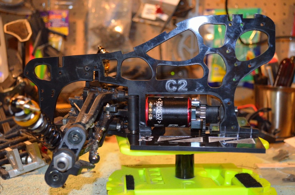 [/URL] [/URL]DSC_0066[/URL] by phukyr[/URL], on Flickr Focus point was a little off but you can see how tight i pushed the tolerances around the other parts. You can also see where it wraps around and locks into the front of the lower chassis. 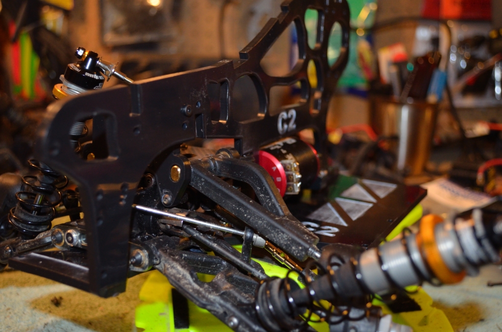 [/URL] [/URL]DSC_0068[/URL] by phukyr[/URL], on Flickr On this side you can see where it ties into the front shock tower-thing and a better angle on the front mount. There will be a piece across the front to keep it from shoveling as well as a bumper that will mount between the front vertical plates.  [/URL] [/URL]DSC_0069_01[/URL] by phukyr[/URL], on Flickr And a look from the back side.  [/URL] [/URL]DSC_0070[/URL] by phukyr[/URL], on Flickr I tried to get some shots from underneath with the body sitting on there so you can get an idea of how it fits.  [/URL] [/URL]DSC_0064[/URL] by phukyr[/URL], on Flickr  [/URL] [/URL]DSC_0065[/URL] by phukyr[/URL], on Flickr So up next will be mock up and cut the passenger side (which is different since the servo will be mounted in it but should be pretty easy). And then start on the back section. There will be two separate pieces that mount to the back of these for the rear of the 'cage' as well as the link and shock mounts will also be on a different piece. The reason for so many pieces is, first, i can get them all out of one piece of delrin like this without as much waste and, second, if anything breaks, or i want to change it, its cheaper to just change out sections. As always, feedback is welcome. :thumb: |
|
| |
|
12-12-2011, 10:13 PM
| #27 |
| Quarry Creeper  Join Date: Sep 2010 Location: Deus est mortuus, logica obtinet.
Posts: 451
|
that is awesome man. i've never seen anyone do something like this! and having that side plate should help keep the body in better shape too, which is always a plus in SC!
|
|
| |
|
12-13-2011, 12:16 PM
| #28 | |
| RCC Addict Join Date: Jul 2008 Location: Sin City
Posts: 1,332
| Quote:
| |
|
| |
|
12-13-2011, 06:26 PM
| #29 |
| RCC Addict Join Date: Jul 2008 Location: Sin City
Posts: 1,332
|
Got some more done today, closer and closer to getting to drive it again, lol. First i got the passenger side front vertical frame done. Wasnt too tough, just had to figure out the servo placement and make a tiny adjustment where the servo saver spring and adjuster is. Pretty much bolted right in once it was cut. Servo is mounted on the inside of the frame to keep clearance between the servo horn and the battery. Rides a little above the front center CVD and center diff outdrive.  [/URL] [/URL]DSC_0072[/URL] by phukyr[/URL], on Flickr Front 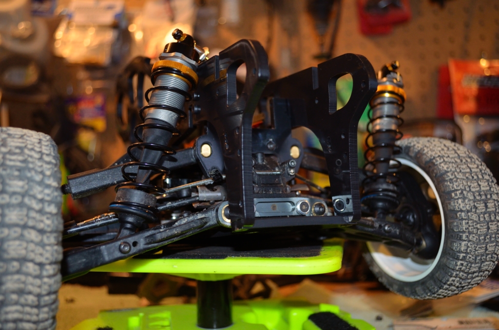 [/URL] [/URL]DSC_0073[/URL] by phukyr[/URL], on Flickr Back  [/URL] [/URL]DSC_0074[/URL] by phukyr[/URL], on Flickr You can just barely see the clearance in this picture where the servo horn is close to the batteries. Flash ended up putting it in a shadow, whoops.  [/URL] [/URL]DSC_0084[/URL] by phukyr[/URL], on Flickr Also got the new rear suspension mounts done. Not sure if i like them yet. The plan was to use these and then additional pieces for the rear cage. Now that ive seen them they are too heavy, especially with all the hardware, and kinda bulky looking. I think ill just use the design and make these the rear cage also.  [/URL] [/URL]DSC_0075[/URL] by phukyr[/URL], on Flickr Mounted 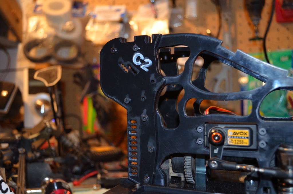 [/URL] [/URL]DSC_0077[/URL] by phukyr[/URL], on Flickr From the inside 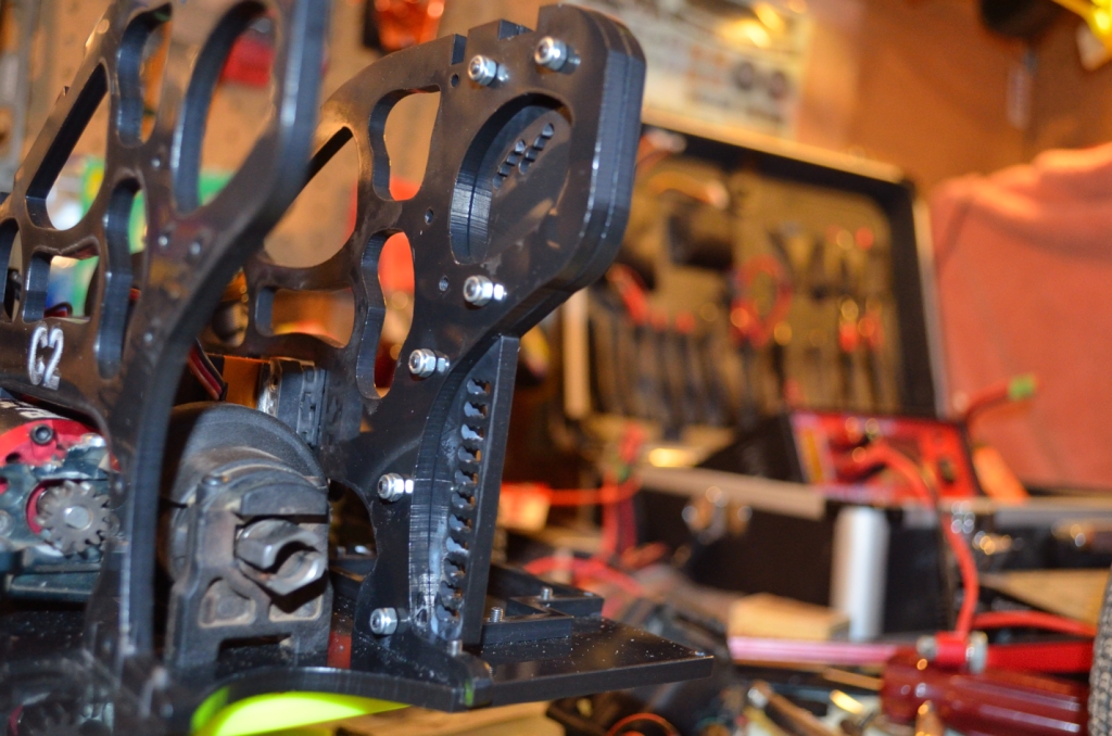 [/URL] [/URL]DSC_0078[/URL] by phukyr[/URL], on Flickr With the suspension mounted up 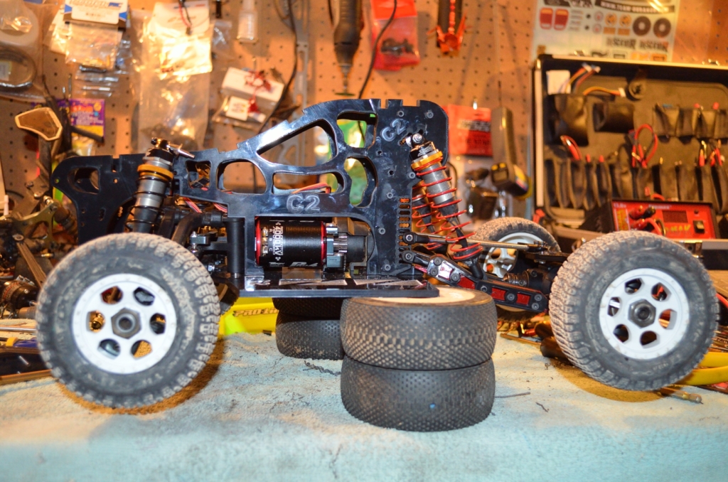 [/URL] [/URL]DSC_0082[/URL] by phukyr[/URL], on Flickr  [/URL] [/URL]DSC_0086_01[/URL] by phukyr[/URL], on Flickr I took a couple under body shots too. I really like how its working out with the body.  [/URL] [/URL]DSC_0080[/URL] by phukyr[/URL], on Flickr 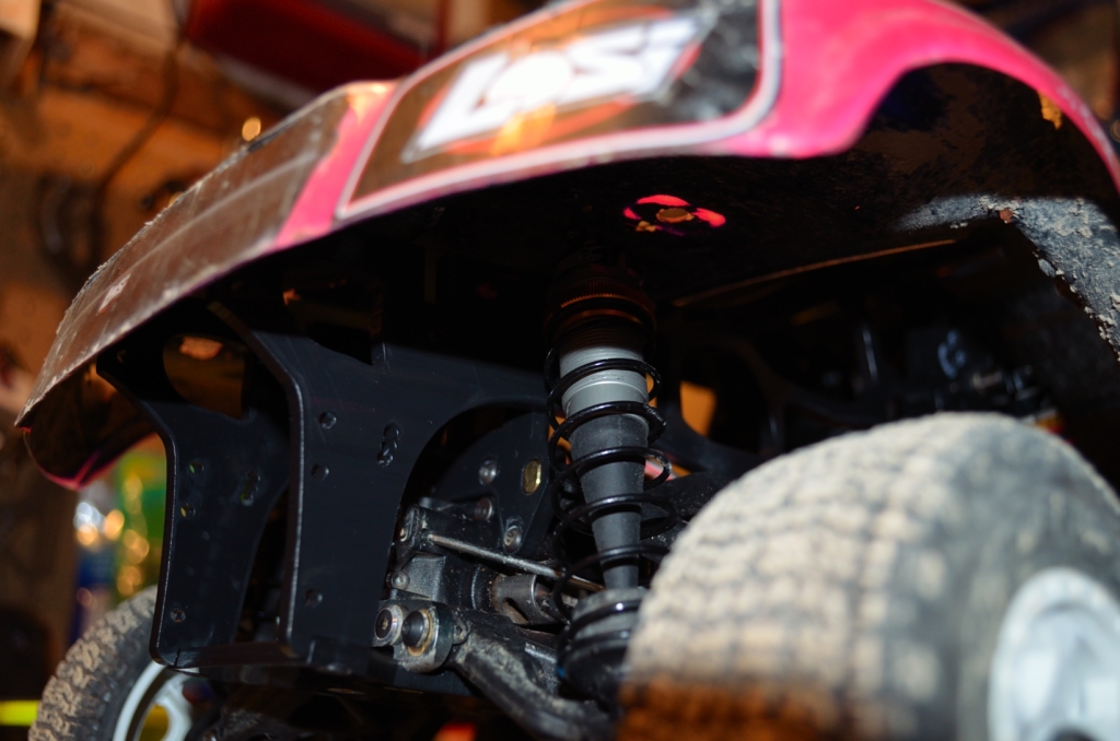 [/URL] [/URL]DSC_0079[/URL] by phukyr[/URL], on Flickr Maybe it needs a flaming battering ram to take care of the hacks and bashers on the track? LOL |
|
| |
|
12-15-2011, 03:44 AM
| #30 |
| Pebble Pounder Join Date: Jun 2006 Location: newark
Posts: 120
|
this is one awsome build .you have alot of talent
|
|
| |
|
12-15-2011, 07:19 PM
| #31 |
| Newbie Join Date: Feb 2010 Location: portland
Posts: 21
|
Love the build it's sweet. Cant wait to see some action shots or video. I need to add that laser cutter to my dream shop list!!!
|
|
| |
|
01-02-2012, 12:27 PM
| #32 |
| Newbie Join Date: Mar 2010 Location: SoCal
Posts: 8
|
Nice to have great tools to help build things like this! The angle of the rear diff has me wondering though.
|
|
| |
|
01-02-2012, 06:36 PM
| #33 | |
| RCC Addict Join Date: Jul 2008 Location: Sin City
Posts: 1,332
| Quote:
| |
|
| |
|
01-05-2012, 12:11 PM
| #34 |
| RCC Addict Join Date: Jul 2008 Location: Sin City
Posts: 1,332
|
Well here we are again. Its always tough getting any hobby stuff done during the holidays but now that the tree is down and the gifts are all unwrapped i had time to get back out to the shop. This is a pretty big update so ill do a few different posts. First up, finished the front shock mount. Its pretty simple. The requirements for me were it had to be easy to change out (in case it broke or i wanted to change the mount positions) and it had to go in and out of the truck without having to disassemble anything else. It slides in under the cage and above the front upper arm mount and then rotates up into place. There are no screws holding it in place. I designed it to be the same height as the original MBX6 tower so even at the longest settings, with the droop taken full out, and the preload spacers all the way at the top, there is still a little tension on the spring. Since this pressure is all pushing up it holds the mount in place (not to mention its a really tight fit to start, the tolerances keep it really snug in there). Also you will notice that i went back to the mugen shocks instead of the durango ones. I like the rango shocks but i want this to be as simple a build as possible using as many mugen parts as possible in case i want to make another one later (ive already had a number of people ask to buy one so simple is good). Shot from the front.  DSC_0132 by phukyr, on Flickr Shot from the rear.  DSC_0134 by phukyr, on Flickr All in all its pretty simple, cut from 1/4in delrin just for some extra strength with 4 possible mounting positions. Eventually i may make another with more adjustment but for now this should get me up and running. Once i can get it on the track for some testing ill know more about what, if anything, needs to change here. |
|
| |
|
01-05-2012, 12:24 PM
| #35 |
| RCC Addict Join Date: Jul 2008 Location: Sin City
Posts: 1,332
|
Next, since i was going back to the mugen shocks i had to take another look at the rear geometry. The rango rear shocks are the same length as the fronts on the mugen, the rear mugen shocks are even longer. While the previous layout did work, it gave way too much travel, and even with the shorter shocks, it was just way too much leverage on the shocks. The spring package would have to be so stiff and the oil so heavy it would have just been a nightmare to tune. I started looking at full scale short course trucks and noticed that most of them mount the shocks much further back in the trailing arms. It seems that massive droop on the rear and the shocks mounted forward of the halfway point on the lower arms is more a desert racing style. Watching short course 1:1 videos you dont see a huge amount of droop in the rear (tho it is more than the front in most cases). New trailing arms.  DSC_0135 by phukyr, on Flickr I made a last minute dremel adjustment so they look a little rough on the ends but easy to fix in the computer for the final set. The shock mount is moved to the rear and the bend in the arms was moved back also. It looked more scale and made plenty of room for the lower spring cups on the shocks. I also took out the cut through on the outer pieces of the arms. It looked cool but i did get a test run in the driveway and they just packed up with snow. Maybe not as scale looking but easier to live with when racing. |
|
| |
|
01-05-2012, 12:41 PM
| #36 |
| RCC Addict Join Date: Jul 2008 Location: Sin City
Posts: 1,332
|
And thennnnnnnnnn.....? Got the rear cage done. There are a few pieces to this. I got a chance to weight the truck finally and it was coming in a little heavy. I know the losi runs like 8 pounds but i was at 7lbs without the rear cage once i stacked the body, battery and electronics on the scale with the truck. I took off the previous rear uprights and, since i was changing the geometry anyway on the rear, made the whole rear half out of 1/8 delrin instead of 3/16. There was also some adjustment of the lines to take out unneeded extra material. In the end the rear cage pieces turned out lighter than the original uprights. Side shot. YOu can see where the upper shock mounts were moved back about 35mm to match the change to the trailing arms and rotated to allow more adjustment.  DSC_0137 by phukyr, on Flickr From the rear  DSC_0138 by phukyr, on Flickr Front 3/4  DSC_0141 by phukyr, on Flickr Then it was time to protect my butt, lol. With a bumper. Im not normally a big fan of a rear bumper in shortcourse, especially 4wd. They just seem to hang out there. BUT i know there is a lot of mass involved with the solid rear axle and no real way to protect it from a direct hit so when i designed the rear cage uprights i put in holes for a slash rear bumper. I have to say im really happy with how it turned out. It fits right where i want tucked under the body and upside down gives it a cool angle.  DSC_0142 by phukyr, on Flickr 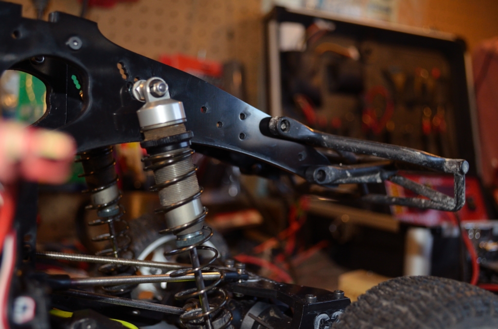 DSC_0143 by phukyr, on Flickr |
|
| |
|
01-05-2012, 01:04 PM
| #37 |
| RCC Addict Join Date: Jul 2008 Location: Sin City
Posts: 1,332
|
So what does that all mean? Its almost done! Side shot with it sitting on the stand to show droop. I have the front droop screws in right now or the front would go down more. I do have plans for the rear to have a type of droop control as well as a swaybar.  DSC_0144 by phukyr, on Flickr And with the body resting on it. This is just sitting right on the cage. Body mounts will be easy but i may get some sticky backed foam for the top of the cage. It will destroy the paint with so little clearance between it and the body. 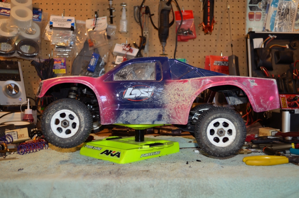 DSC_0146 by phukyr, on Flickr Rear shot showing where the bumper hides under the edge of the body. Looks much cooler tucked up in there unlike some SCT rear bumpers.  DSC_0149 by phukyr, on Flickr  DSC_0152 by phukyr, on Flickr Some shots with the body.  DSC_0153 by phukyr, on Flickr  DSC_0154 by phukyr, on Flickr And now the weight  DSC_0155 by phukyr, on Flickr Surprising how much the body weights when its dirty, LOL.  DSC_0156 by phukyr, on Flickr And a little balance test just to see where its at front to rear. 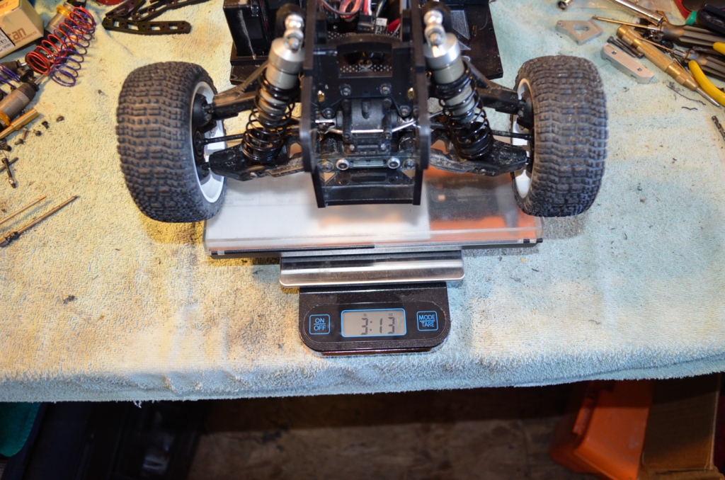 DSC_0157 by phukyr, on Flickr 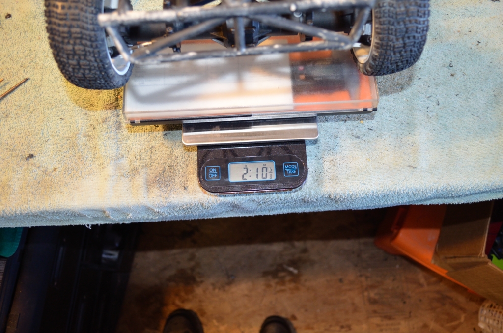 DSC_0158 by phukyr, on Flickr So next on the list. It needs the cross bracing finished in the rear, the droop control and swaybars for the rear, the front bumper and guard, finsih the battery hold down, and the body mounts. Should be able to knock all that out pretty simply this week. |
|
| |
|
01-05-2012, 01:44 PM
| #38 | |
| RCC Addict Join Date: Mar 2010 Location: Auburn, MI
Posts: 1,177
| Quote:
I have been thinking about a table top CNC for a while now, and finally have the cash to buy one. Now I just need to buy a house to have a place to run the machine. Maybe we should get in business.. Keep up the good work, looking great. | |
|
| |
|
01-09-2012, 07:39 PM
| #39 |
| RCC Addict Join Date: Jul 2008 Location: Sin City
Posts: 1,332
|
Been mostly suspension work latley. Right now its mostly working by feel since i cant get out and test it but its going to be in the ballpark when it hits the dirt. Shocks - I want the shock oil range to be in the 20-40 weight area like a store bought truck. However with the mugen shocks and stock pistons from the buggy they were WAY too stiff. Even with 20 weight oil it would have bounced all over (and did when i tried it on the ice in the driveway). So what to do, what to do? Make new pistons! These are 1/8 delrin cut on the laser to be blank. Currently i have them drilled 1mmx6holes and they feel good with 20# oil. Thats a little on the low range of where i want it so ill prolly go 1.0x8 to make it a little easier to tune. 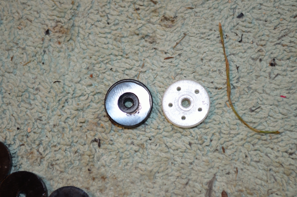 DSC_0166 by phukyr, on Flickr  DSC_0167 by phukyr, on Flickr So far so good. Its feeling pretty dialed. I like the front suspension heavier than the rear on my 4wd so the 1.0x6 ones will prolly go into the front. And..... Swaybars! These things turned out pretty awsome. Hot Racing has been hit or miss in my personal experience. I dont know how durable these will be but they went on with no mods other than the length on the links and are nicely machined. The only thing i see that may be an issue is the setscrews that hold the arm on the spring arm. They are kinda small but i loctite everything so we will see. On to the pics! You get two sets in the package so i have spare parts for later i guess if i need them.  DSC_0169 by phukyr, on Flickr And whats in the package for one set. The arms, 3 different spring rods, the connecting rods with ball ends installed, setscrews, the plastic spacer tubes, 4 tapped ball ends and 2 screws. I guess the lower link point on the wraith already has a screw end there to use, hence, only 2 screws.  DSC_0170 by phukyr, on Flickr I guestimated the length of the arms from looking at the pics and placed the holes accordingly in the last cut of the rear cage panels. I got pretty lucky and they bolted right up, even the width was right on the money with only 1mm to spare on each side. The only thing i changed was i swapped the stock ball ends with some durango ones that were longer. They are 70mm end to end and the rods are turnbuckles for finer adjustments to make them exactly the same length as well as tweak where they are based on ride height.  DSC_0171 by phukyr, on Flickr Fully compressed. The length was important because the body will ride right along the upper edge of the cage so the arms couldnt move above that at full compression. They are well past the rear bumper mount tho it doesnt look like it in this pic you can see the clearance in the very last pic. They can go higher if needed.  DSC_0174 by phukyr, on Flickr And full droop/extension.  DSC_0175 by phukyr, on Flickr I took a few shots just to kinda show the effectiveness of the swaybars. For those who dont know or are new to racing, the swaybar links the side to side reaction of the suspension. This adds a spring effect that tries to keep the vehicle level and keep one wheel from traveling too much further up (or down) than the other. While this may initially sound like something you wouldnt want in offroad, you really do. If you had no sway control every time you went into a corner the body/chassis would roll over to one side when the outside suspension compressed, this also takes weight off the inside suspension causing even more roll. If you have any kind of grip on the tires it makes it very easy to flip over. This is especially important on any type of solid axle vehicle (except for rock crawlers). This is the same in rc cars and the 1:1 car in your driveway. This is a bit of a random comparison since i needed one hand to hold the camera. With the swabars hooked up and the weakest spring rod installed. 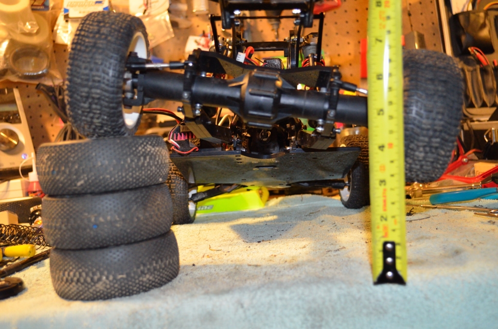 DSC_0176 by phukyr, on Flickr ... and after pulling the setscrew out of one of the arms so there was no swaybar effect... the wheel went straight to the bench and would have went more, lol. 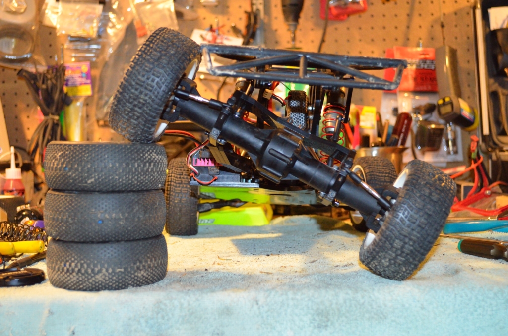 DSC_0177 by phukyr, on Flickr And a couple more shots just for those who like pics. 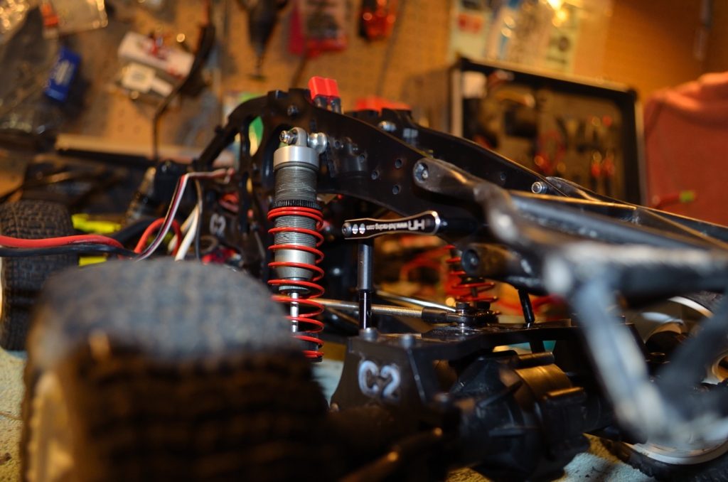 DSC_0178 by phukyr, on Flickr  DSC_0179 by phukyr, on Flickr |
|
| |
|
01-10-2012, 07:27 PM
| #40 |
| Quarry Creeper Join Date: Sep 2010 Location: t(._.t)
Posts: 465
|
cool..... the roll cage is..... interesting |
|
| |
 |
| |


 Linear Mode


