| |
| |||||||
 |
| | LinkBack | Thread Tools | Display Modes |
 07-11-2009, 11:02 AM
| #1 |
| Tire&Foam Extraordinaire   Join Date: Jun 2007 Location: C.I. Compound, Tyler, Texas
Posts: 5,601
|
I built this set of axles for a local club member who is working on his first scaler. It's going to be a 1.9 Jeep using a New Bright body. He had no experience with TLT's, so I thought I would post a build thread to help inform someone else of what is needed to get a stock TLT case ready for scale or comp use. Here we have a new Tamiya TLT case: 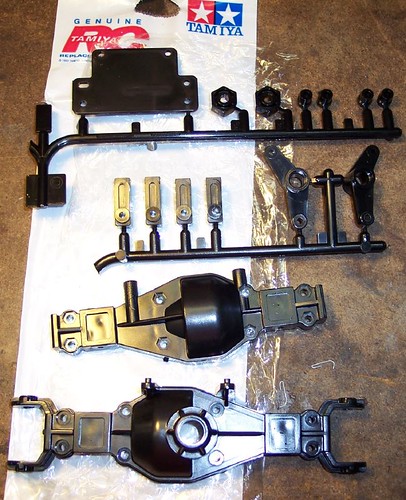 The first thing needing modification is the steering stops and link mounts from the axle case that are boxed in red: 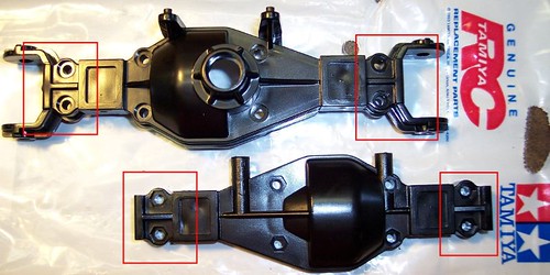 They need to be filed down smooth to the axle housing. You are removing these plastic stops that protrude from the axle because they limit steering. They also need to be removed to make the area flat for the link mount. Be careful to not remove too much. If you remove too much you can weaken the housing and if you plan to add Axle C's or Rear lock outs later they will be sloppy. Axle C's and rear lockouts should fit snugly. You want to leave the embossing / recess put there for the nut and bolt head. They should look something like this: 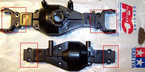 |

|  |
| Sponsored Links | |
| | |
|
07-11-2009, 11:02 AM
| #2 |
| Tire&Foam Extraordinaire Join Date: Jun 2007 Location: C.I. Compound, Tyler, Texas
Posts: 5,601
|
The next modification I like to do is remove the plastic locating pin on the axle. It is pictured below in the red box: 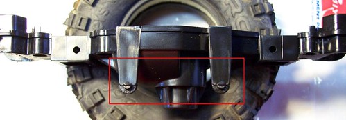 I file the area flat and then drill a 3mm hole where the locating pin was. I do this so that I can bolt the link plate / servo mount directly to the axle to make it stronger. This is completely optional, but if you do not do it, you only have two screws going into the axle housing and risk it failing easily. 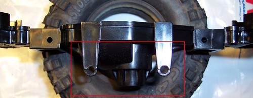 |
|
| |
|
07-11-2009, 11:03 AM
| #3 |
| Tire&Foam Extraordinaire Join Date: Jun 2007 Location: C.I. Compound, Tyler, Texas
Posts: 5,601
|
The next area I look to modify is a lip of plastic cast into the housings. They are pictured below in the red boxes: 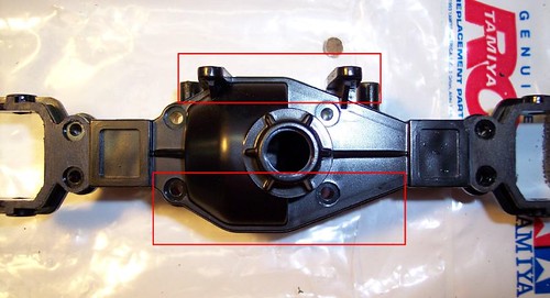 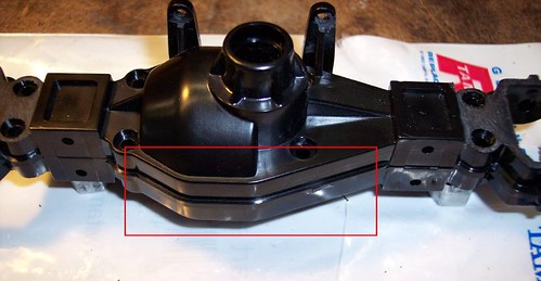 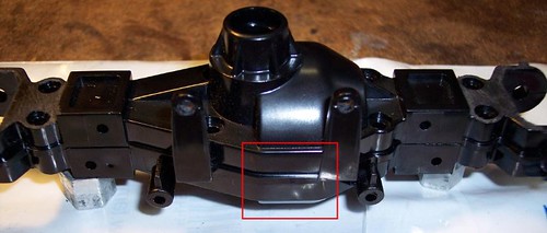 The area at the top needs to be removed in order to allow after market link plates to be used. I remove the bottom lip so it does not catch on the rocks and I try to round the bottom of the housing to make the axle more smooth and to appear more round and scale. Here is the top lip removed. You do not need to remove all of it, just enough to allow a flat link plate to sit flush on top of the axle. 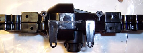 Here is the bottom: 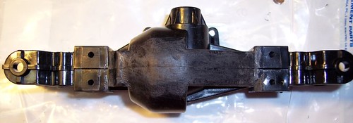 Here is the axle viewed from the pinion side: 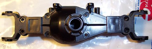 |
|
| |
|
07-11-2009, 11:04 AM
| #4 |
| Tire&Foam Extraordinaire Join Date: Jun 2007 Location: C.I. Compound, Tyler, Texas
Posts: 5,601
|
This next step is completely optional and done more for scale appearance. I own a bead blast cabinet and once I have the modifications done to the housing, I like to bead blast the housing. It removes the sheen of the plastic and "ages" the look of the axle. I am sure there are other methods that could be used to accomplish the same look using either chemicals, sand paper, rocks, etc. The bead blasting produces a look like this: 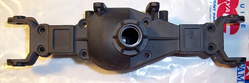 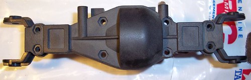 |
|
| |
|
07-11-2009, 11:04 AM
| #5 |
| Tire&Foam Extraordinaire Join Date: Jun 2007 Location: C.I. Compound, Tyler, Texas
Posts: 5,601
|
These particular axles are going to have CVD's in them and they needed to be modified in order to take advantage of the full steering RCP CVD's offer. A stock TLT steering knuckle looks like this: 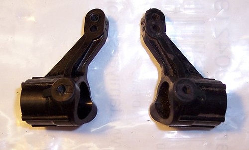 I used an air die grinder with a rotary file and remove the area on the inside of the knuckle. This be accomplished by a dremel or can be simply cut away as well. I also bead blast these as well. the knuckle on the right is ready to be installed: 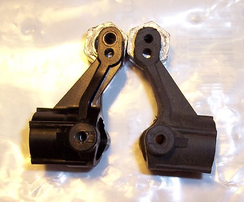 By modifying the steering knuckles and the housing you end up with steering like this: Top view: 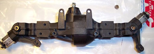 Bottom view: 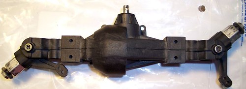 Here is a view of the completed front axle: 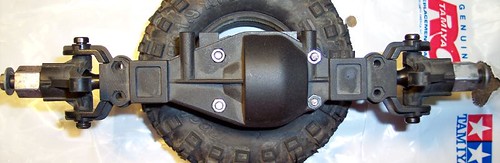 And now both the front and rear: 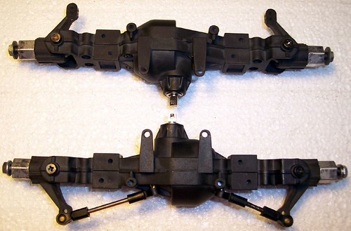 |
|
| |
|
07-12-2009, 11:54 AM
| #6 |
| RCC Addict Join Date: Nov 2005 Location: Kansas
Posts: 1,280
|
bead blasting makes those look AWESOME!  Interesting work on the knuckles too, have you ran em like this before? Are they more prone to breaking? |

| |
|
07-12-2009, 12:01 PM
| #7 | |
| Tire&Foam Extraordinaire Join Date: Jun 2007 Location: C.I. Compound, Tyler, Texas
Posts: 5,601
| Quote:
Yes, I have run the knuckles like this on scale rigs and they hold up fine. Usually the plastic C will fail if they take a hard enough hit before the knuckle fails. Quality aluminum knuckles like the RCP max clearance steering knuckles already have this much clearance. Cheaper aluminum (garbage brands) ones like the Yeah Racing brand will require you to clearance them and so will the RC4WD knuckles. | |
|
| |
|
| |


 Linear Mode


