| |
| |||||||
 |
| | LinkBack | Thread Tools | Display Modes |
 05-22-2007, 04:47 PM
| #1 |
| Rock Crawler Join Date: Dec 2005 Location: Mesa
Posts: 602
|
Last summer I built up a simple trail rig with a twist after seeing the "Reverse Cowgirl" rig. That was called the Misfit. 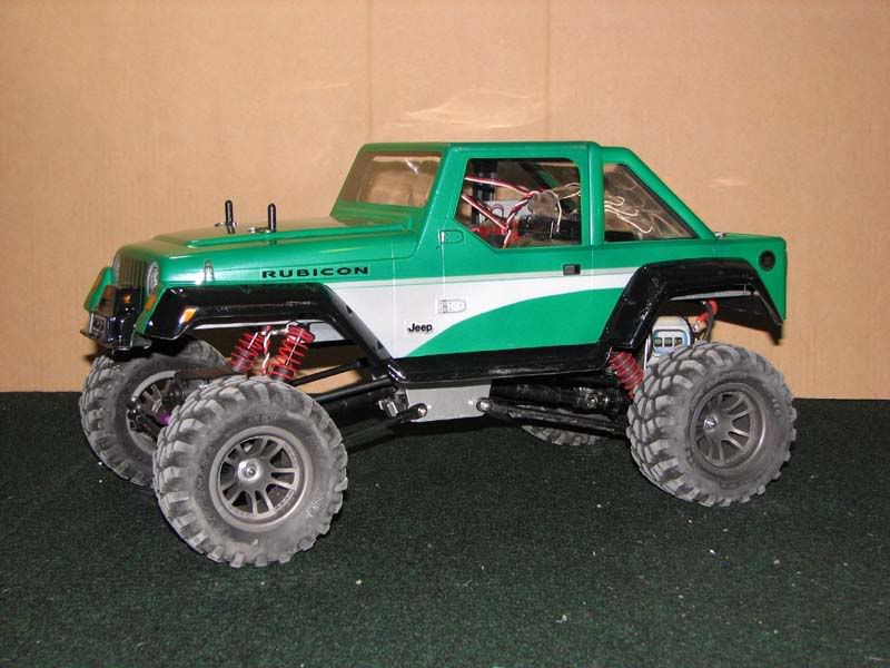 I never really found a good place to run it except for some rocks on the garage floor. Long story short, got bored with it, changed bodies and W/B then got bored again with just crawlers and traded it away as this. 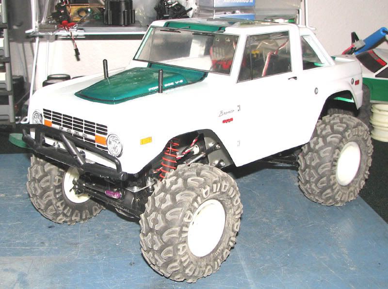 Here it is, next summer and I found that I missed sitting out in the garage waiting for a cop to give me a DUI for driving an RC on a bunch of rocks in my own garage (I've seen a guy get a DUI on bicycle so it's not a far fetched as you migh think). So I decided it was time build the Misfit again. It's so easy a noob can do it. Stats are basic TLT axles with Blackfoot stubs TLT Shocks with Traxxas Rod ends Stampede Trans with GD-600 Pinion/Spur/Slipper eliminator (I'll get to that) Revo Pushrod links 35T lathe Stampede rims with Mashers (not narrowed, either of 'em) Stampede shafts and steel yokes all over the place Rebel2 ESC and 645mg servo I wanted to use the stock TLT chassis plates with out modification just because everyone else starts out hacking up the stock plates or replacing it with any one of the very fine chassis's availible through vendors on this site I always fab up my own servo mounts but this time I used 1/8 alum plate for the rear motor mount. I dremeled out some alum angle stock to sandwich between the motor/GD combo 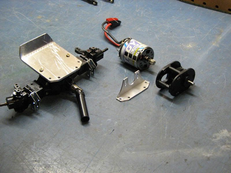 then you bolt it all up like this 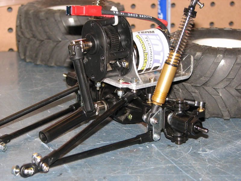 Well boys and girls, in the next lesson we'll go over the how to connect the motor to the trans Last edited by Mriswith; 05-22-2007 at 06:25 PM. |

|  |
| Sponsored Links | |
| | |
|
05-22-2007, 06:24 PM
| #2 |
| Rock Crawler Join Date: Dec 2005 Location: Mesa
Posts: 602
|
Next up is the trans. I just love cutting on a stampede tranny. That plastic motor plate, well I don't like it, so any excuse to cut it off. The 'pede gets to a respectable compact size and will drop right between the stock width TLT chassis plates. Pull the spur and slipper assembly of the top shaft and cut of the threaded portion. You'll want to leave the hex part because thats where the traxxas steel yoke goes. The next part took 2 more bits of angle aluminum to a mount for the trans. The lower links bolt the angle in place. Yea, yea, yea it will and does hang up but if I used cutting board or delrin, my drive line angles would be sharper than I want. I'll eventuall just Shoo Goo some scrap lexan to the bottom so it will slide better. That which does not help you, makes you drive better. Besides, it spends most of it's time on my garage floor with more loose screws than just me behind the controller. If I can't make a line, I move the rocks on the way to fridge. Before I slipped in the trans I put on the half shafts. Now that the trans is in I just bolt up the rear end up in the Stock tlt locations and slide the drive shafts together. So far no new holes in the chassis. Trans fits like a glove |
|
| |
|
05-22-2007, 07:51 PM
| #3 |
| I wanna be Dave Join Date: Sep 2005 Location: Houston, TX
Posts: 16,952
|
Looks good!!
|
|
| |
|
05-22-2007, 11:07 PM
| #4 |
| Pebble Pounder  Join Date: Sep 2004 Location: Southeast Missouri
Posts: 119
|
thats a great Idea. good write up
|
|
| |
|
05-23-2007, 09:38 AM
| #5 |
| Newbie Join Date: Dec 2006 Location: vancouver, bc
Posts: 41
|
looks awesome man... im starting up one aswell... keep itk up..
|
|
| |
|
05-23-2007, 11:13 AM
| #6 |
| Rock Crawler Join Date: Dec 2005 Location: Mesa
Posts: 602
|
Well let's see, covered the rear end and trans, time for the front. Nothing special up front other than where I mount my upper links. I like using the same length rods for upper and lower so I make my own servo mounts. I trace out the stock mounts on alum. I line up the upper link mount holes to the lower link mounts holes. 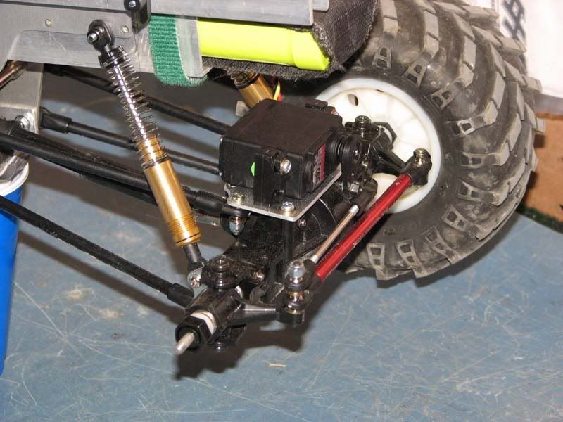 I can reverse the lower link mounts and flip the upper links to the top to gain more clearance with out changing geometry. I haven't because of the body/tire clearance. I like where it's at and I don't feel like complicating the body mounts. You can also see the somewhat stock TLT shocks. I cut off the cap mount point, drilled a hole through the cap and screwed a rod end on. The trick was coating the countersunk head screw with shoo goo to seal it. 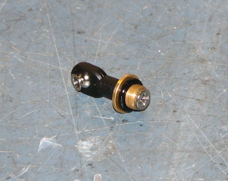 Next up was the battery mount. I didn't want to mess with fancy custom packs, just good old fashioned stick packs. So 2 more chunks of angle aluminum drilled to match existing holes. 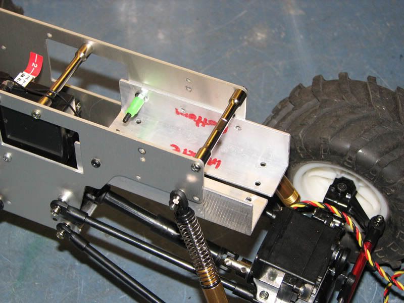 A Velcro harness for the pack which loops around the fuel tube sleeved screws holds one end while a velcro strap holds the other. 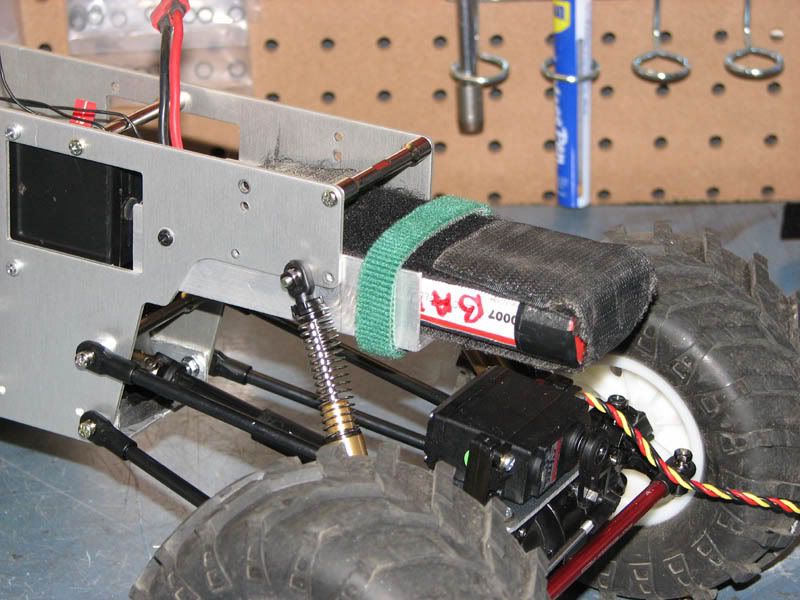 The battery is way up front, chassis mounted and just clears the servo at compression. |
|
| |
|
05-23-2007, 11:13 AM
| #7 |
| Rock Crawler Join Date: Mar 2007 Location: Colorado
Posts: 635
|
innovative, looks really good.
|
|
| |
|
05-23-2007, 11:30 AM
| #8 |
| Rock Crawler Join Date: Dec 2005 Location: Mesa
Posts: 602
|
I can't take credit for the original rear motor idea, I saw it here ..Reverse Cowgirl . I just went in a completely different direction .. and got lost.
|
|
| |
|
05-25-2007, 12:40 AM
| #9 |
| Rock Crawler Join Date: Dec 2005 Location: Mesa
Posts: 602
|
Next up is the body mounts. Nothing fancy, just lengths of alum. channel. They are held on by going through the stock chassis body mount holes and into the stock steel cross braces. I'm using the stock TLT body mounts and those are screwed into the channel. 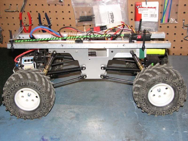 You can also see how I mounted the reciever wire using the stock TLT mount. I did end up drilling one hole in the chassis but that was for mounting a Traxxas TQ3 reciever using the mounting holes in its case. That radio went bad on me so I grabbed an HPI system I had laying around and just velcro'd it to the battery harness. Those antenna wires on the HPI 3 channels are long, REALLY long. For kicks I measured it out 39 inches. All things considered, this thing has good flex. 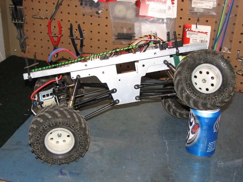 And now for the body on shot. I really liked the look of the Rubicon body but at the time I made the first Misfit, everyone was running 'em so I changed it out for the Bronco. Now that the Bronco and jeep have been done to death I figured it was time to go back to the original. I could have gotten the original body back from a friend of mine but he's already run it on his Savage. Yea I don't want it back even with the plastic coathanger rollcage he made for it, mostly because the cage is holding the body together. Never thought I would see that body catch 10 foot air when I painted it.   Not very creative on the color scheme but I liked it... and I didn't have enough green left |
|
| |
|
05-25-2007, 09:27 AM
| #10 |
| Newbie Join Date: May 2007 Location: Canary Island
Posts: 32
|
Good work, congratulations...
|
|
| |
|
05-26-2007, 12:21 PM
| #11 |
| Rock Crawler Join Date: Dec 2005 Location: Mesa
Posts: 602
|
Here's a couple action picks my little rock pile    |
|
| |
|
05-26-2007, 07:18 PM
| #12 |
| Quarry Creeper Join Date: Aug 2006 Location: Pilgrim,Ky
Posts: 293
|
Very nice build
|
|
| |
|
05-26-2007, 09:00 PM
| #13 |
| Quarry Creeper Join Date: Feb 2007 Location: East Aurora
Posts: 289
|
yea nice write up, i am thinking about doing that with this tuber i am making!
|
|
| |
|
05-26-2007, 09:54 PM
| #14 |
| Rock Crawler Join Date: Dec 2005 Location: Mesa
Posts: 602
|
Well I was a little bored earlier and needed a break from my new TLT project so I got around to editing a video of the Misfit's first run. This design works pretty well from what I can tell. I haven't got any terrain around here for really crawling, it's farmland and mudholes for as far as a tank of gas will take you.  I've been told I have an odd sense of humor when it comes to the audio tracks in my videos. |
|
| |
|
05-26-2007, 10:31 PM
| #15 |
| Pebble Pounder Join Date: May 2006 Location: Abington
Posts: 188
|
Sweet!!! I'm glad to see you made another one. I had the original Misfit at one point. The thing was unstopable and it was the original chassis. Good luck with the new one.
|
|
| |
|
05-26-2007, 11:37 PM
| #16 |
| Rock Crawler Join Date: Dec 2005 Location: Mesa
Posts: 602
|
That good huh? What I'd really love to see, is it outperform a comp setup, I doubt it but I'd love to see a stock chassis whoop up on a comp chassis chassis just because I like to be a little different. Like I said I don't have any good terrain nearby other than whats in my video. I'm glad to hear that such a simple design works well. Just seeing other video's and the type of terrain in them, I figured it would do very well. This incarnation should perform a little better than the original. I got it wider with the Blackfoot stub axles and I think the battery placement is a little lower and a bit more forward. I had fun with the original Misfit and I haven't had a crawler since then. My friends had been giving me grief about getting rid of it (and my b$#ching about not having a crawler) so it was time to do it again... and again. Look for my FJ in the 2.2 scalers soon, it's already on the workbench. I'm truly addicted, this Misfit is my 9th version of a TLT crawler and the forth coming FJ will be number 10. That doesn't include my 8x8 (which has been in roller phase then parted out. Then a runner and now back into redesign for a scale suspension Last edited by Mriswith; 05-26-2007 at 11:55 PM. |
|
| |
|
06-09-2007, 01:05 AM
| #17 |
| Rock Crawler Join Date: Dec 2005 Location: Mesa
Posts: 602
|
Well I got my Bushwackered FJ running and the last couple brain cells don't feel like working on it right now. The FJ has more to be done but I felt coming back to the Misfit. Generation 2.5 is just like the original in that I do hang up a bit on the chassis. I did Shoo Goo up a scrap lexan skid for the bottom of the chassis and it does help but I need a project. If I don't have something on the work bench I tend to get grumpy. So for the safety of my co-workers I decided to mod up the Misfit. I swapped around my link mounts for a little more clearance. The front (not the axle with the motor) is what I figured I'd try first.  When I did that, it gave me a touch more wheelbase which slid my driveshafts farther apart. I never did modify the sliders for length and the switch was just enough to be too much and allow them to seperate at full droop. I don't have any spares since I built my FJ so I figured it was time for a change. Since it seems more fun to redesign the whole truck than to just mod the shafts, a full rebuild is in order. So now we enter the 'design on the fly while getting your buzz on since it's the weekend phase'. It's Friday night or rather early Saturday morning and this is what the Misfit (and my workbench) looks like at the moment.  I should mention that I'm not a good role model for the young and that probably soon I'll come packaged with a disclaimer. Anyhooo... I had a wild hair and decided to try something different for the belly pan. I bent up some of the 1/8" alumn. I got left over from the FJ. this stuff is about a 6061 material and I'm not looking forward to bend it again. I got a little tiny 4" vise and it's definately not enough. It is soft enough to bend into a 45 degree with out stress cracking but it is not easy. I'm thinking I should have just modded the shafts at this point.   I've got one end with the links mounted inside the chassis and one outside. I'm gonna mount to the inside but I have to trim up the 'pede case some more ( I love that part ) and clearance the belly pan around the lower link mounts. I finally saw a post the other day about 4w steer and how to set it up with Futaba's 3PM. I have one and have been really wanting to try it out. I know 4w steer isn't comp legal but this rig will probably never see a comp and if it does I've already got a lock out setup from my 8x8 project ... so |
|
| |
|
06-23-2007, 11:57 PM
| #18 |
| Rock Crawler Join Date: Dec 2005 Location: Mesa
Posts: 602
|
I ended up scrapping the chassis, it didn't end up to my standards. But I did do the rear steer. I did try a chassis mounted setup with a bell crank on the axle. I ended up with too much bump steer. The stock TLT shocks are too light and I get a bit of body roll. I fabbed up a new rear motor mount out of the same 1/8" Alum. plate and clearanced it for the cross over steering. The servo mount is just some 1" alum. angle trimmed up and bent to mount on the axle with stock TLT servo mount posts. I used the stock TLT center link rod with a pair of left over Traxxas rod ends and some 6/32" threaded rod for the servo link. I left a stockball joint on the other side of the axle for a rear steer lock out using the stock cantilever links from the original TLT kit. Here's some pics 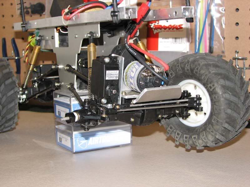 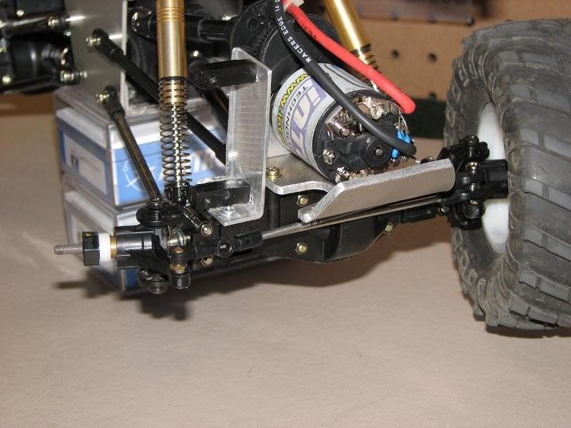 And some shots of it completed with the steering modes What I call Coordinated mode (You military guys who tow airplanes should recognized the terms) 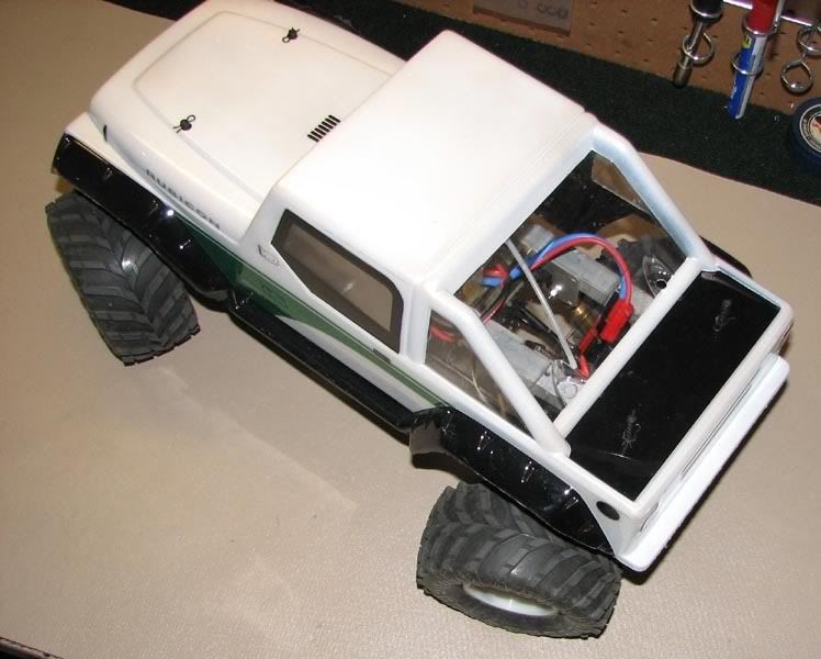 and Crab mode 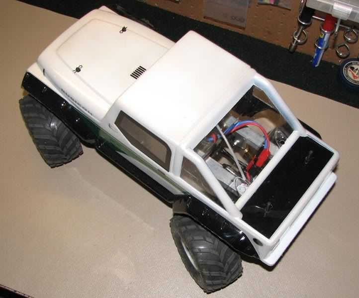 Now I just need to get a strong enough servo, the one picture is just an extra I had laying around. |
|
| |
|
| |


 Linear Mode


