TheLetterJ
RCC Addict
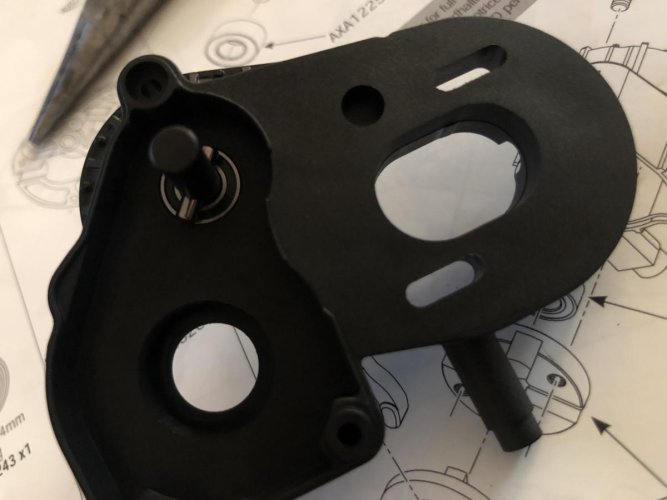
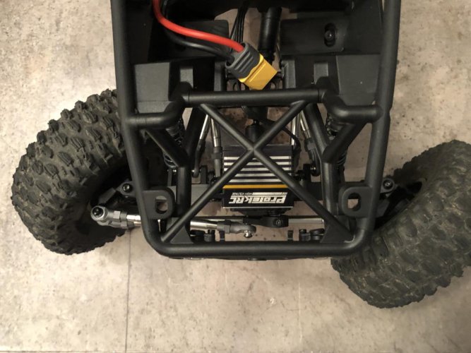
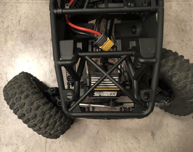
Try the stock pinion, I ran into the same issue and thought I may have gotten the pinion’s mixed up. When I switched them out the other one is spinning more or less fine, but still not as smooth as I like. Will see how it goes when I get a driveshaft shimmed up and have it on the transmission.
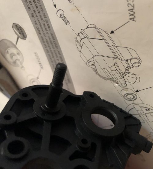
I'll give that a shot tomorrow. In 1:1, mixing and matching pinions is a big no-no, since the pitch (if that's even the right word?) of a helical cut pinion gear of a given tooth count (in this case 8) is different, depending on the tooth count of the ring gear (27 or 30.) There's much less on the line in this application though, so I'll certainly give it a try!