• Welcome to RCCrawler Forums.

    It looks like you're enjoying RCCrawler's Forums but haven't created an account yet. Why not take a minute to register for your own free account now? As a member you get free access to all of our forums and posts plus the ability to post your own messages, communicate directly with other members, and much more. Register now!

    Already a member? Login at the top of this page to stop seeing this message.

Cutting a motor commutator & motor tweaks

CIMG5961.jpg


you can change that lathe to be what ever side you need it to be as long as both sides the top part, bit holder, are V-grooved. you just back the adjuster out of it so it comes off the v-grooves. simply spin it around and thread it back on.

it would be this way after
ADSC00242-1.png


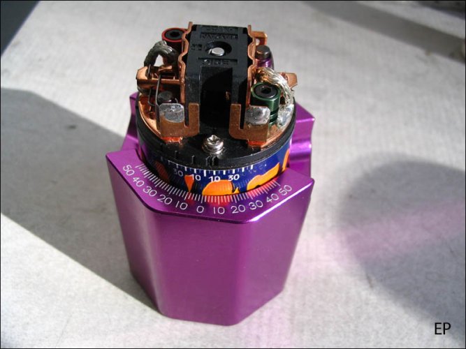
heres a picture from my motor thread from TLTRyan with the same lathe ...... look at the bit angle
IMG_0112.jpg
and


3S is way to fast for a lathe, mines a 65T slave that I only spin at 5V for mirror finish cuts everytime.
 
So what would you do to a 35t integy lathe motor new out of the bag. Turn comm yes. But, best way to break it in, different brushes, different springs, best way to time them.

On a MOA rig. Should I run the front motor backwards or the rear or does it matter?

Thanks
 
The integy springs seem pretty stiff, I haven't measured them. You could go with a 15oz or 13oz spring (very heavy) to help the drag. The brushes are ok once broken in. You almost have to shape them unless you want to use water or much time for the break in period.

I would recommend 6 to 12 degrees of timing on them. Running them at zero timing is risky because of the loose construction tolerances, it is likely to ruin the comm.
 
A integy can has no marks and the one I'm working with has no sticker at all. So How do you time this motor and all the others?

Thanks maybe
 
On the can there are four little indentations around the top where the endbell sits, and also four indentations on the side to hold the magnets in place for assembly. The upper dent at the top that is between the magnet dents can be reffered to as zero timing. The endbell setscrews have a little mark next to them that also represents zero timing.

This can also has a hash mark and zero stamped into it.

attachment.php
 
The integy springs seem pretty stiff, I haven't measured them. You could go with a 15oz or 13oz spring (very heavy) to help the drag. The brushes are ok once broken in. You almost have to shape them unless you want to use water or much time for the break in period.

I would recommend 6 to 12 degrees of timing on them. Running them at zero timing is risky because of the loose construction tolerances, it is likely to ruin the comm.

John, will advancing the timing make it run slower in reverse than forward? I just cut my Integey coms with a cobra lathe I have and read here were you say to run the timing between 6 and 12 degrees. Also if i remember correctly you can turn the bell to the left or right to change timing, witch way would i turn it to get the timing you are talking about...thanks for the info..."thumbsup"
 
In theory, you will have a tad less power in reverse..but, who cares.....less comm wear, more power in forward, etc are worth it......besides, going in reverse is BAD anyways....I doubt you would ever notice the less power in reverse anyways....

Counter clockwise if you are looking down at the endbell will advance it....

And the 4 tabs stamped into the can are hardly to hold to the magnets in place during assembly.....they don't even come close to touching them. They are purely there for one reason.....to give the timing ring something to hold onto.....they serve no other purpose. The magnets are put in place unmagentized and held there my a special insert thats removed after the glue cures....I've seen pics of the procedure at sagami.

Later EddieO
 
Last edited:
And the 4 tabs stamped into the can are hardly to hold to the magnets in place during assembly.....they don't even come close to touching them. They are purely there for one reason.....to give the timing ring something to hold onto.....they serve no other purpose. The magnets are put in place unmagentized and held there my a special insert thats removed after the glue cures....I've seen pics of the procedure at sagami.

Later EddieO


The four tabs stamped to hold the magnets, not the top dents... ... ........ ....... .... ......... .................. ........... .......... ............. ... ........ .. ......... . .......... .... ..... .... ......... .... ....... .... ...... ... ........ ........ .... ..... ... .......... ....... ...... . ........... .... ... ...... .... .... ............


wpid-1289607754604.jpg
 
Last edited:
Nice! 3 amps should handle everything out there!

Sweet, 8 pounds! That'll balance out the lead acid 6 volt battery I'm gonna use just right.

New technology. Fantastic.
 
Thanks alot guys for the info, Myself and helhedded are ganna go do some practicing tomarrow so I'll give the advance timing a shot and see how it works for me...I can use all the help I can get after being out of crawling for a year........lol
 
So to further my confusion I quote this off McMaster: "All are finished and ground. When used in a lathe, styles AR, BR, FR, GR, and ER are fed from right to left (as shown). Styles AL, BL, FL, GL, and EL are fed from left to right." With the use of the nice picture: http://www.mcmaster.com/#al-style-lathe-tool-bits/=9h9i4i

This would indicate the AL is the correct style??

On a side note, I got the lathe to cut pretty nice tonight, but I was running it on 3S, with the blade way high, rotated 90* clockwise and mounted at an angle.:lmao: Only prob is that it can't cut all the way to the windings, the backside of the bit will contact the tabs on the arm.

CIMG5961.jpg

Yeah you need an AR bit as was said a few times.

That said I have the same lathe and picked up a couple carbide bits to try (and for backups) and they didn't work for shit. The tool nose radius is too big and the edge doesn't have enough relief nor is sharp enough. Also you have to take light cuts with this lathe, no more than a .001". It helps to get a scrap arm and experiment with the voltage (speed) to get the best cut.

When I machine copper (my real job) I use a HSS bit on the small stuff because you can get a super sharp edge on it which is what you need here. Havn't got time to grind a HSS bit and screw with it yet. I'm not shelling out the money for a PCD cutter, too touchy and too expensive.
 
Last edited:
I picked up several carbide bits from McMaster-Carr and they work great. At $5/ea I can just toss them when they dull. BTW I have the same lathe.
 
Something isn't right.
 

Attachments

  • IMG_3189.jpg
    IMG_3189.jpg
    95.1 KB · Views: 638
Back
Top