:lol:
-
Welcome to RCCrawler Forums.
It looks like you're enjoying RCCrawler's Forums but haven't created an account yet. Why not take a minute to register for your own free account now? As a member you get free access to all of our forums and posts plus the ability to post your own messages, communicate directly with other members, and much more. Register now!
Already a member? Login at the top of this page to stop seeing this message.
You are using an out of date browser. It may not display this or other websites correctly.
You should upgrade or use an alternative browser.
You should upgrade or use an alternative browser.
Smokin' Mamba BEC?
- Thread starter microgoat
- Start date
microgoat
I wanna be Dave
I think I'm getting it now. My mistake was in assuming the negatives were independent, and changing the voltage of the motor side introduced a potential voltage that had to go somewhere.
Like this rig needs to carry another four or five cells. It's already close to seven pounds :lol: Thanks JIA.
Like this rig needs to carry another four or five cells. It's already close to seven pounds :lol: Thanks JIA.
microgoat
I wanna be Dave
Thanks JIA
That was it. After spending the morning re-soldering the radio leads (and I did find a receiver pack of sorts, a 20-year-old 5-cell pack that came with my Blackfoot bodies (used to power the lights, lasted about two minutes) :lol: everything works now. The Mamba powers up on 8 cells and nothing smokes.
That's the difference between a PRO (JIA) and just another wanker (me). Thanks bud :mrgreen:
just saw this. Whenever I have a seperate servo power, I totally seperate the servo and motor circuits for this very reason.
microgoat
I wanna be Dave
This is how we learn. By blowing sh!t up :lol:
ROFL...imagine that! Someone keeping me around for my mind! :lol:
Here's why the servo lead was cooking.
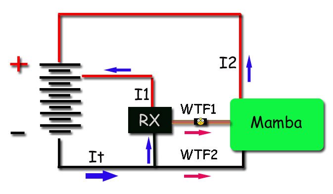
When the RX and ESC are connected they form a parallel voltage divider.
The fat blue arrow represents total current flow through the circuit.
The two smaller blue arrows are branch currents through the RX (I1) and through the ESC (I2).
More coming...can't seem to get multiple attachments in the right order.
Here's why the servo lead was cooking.
When the RX and ESC are connected they form a parallel voltage divider.
The fat blue arrow represents total current flow through the circuit.
The two smaller blue arrows are branch currents through the RX (I1) and through the ESC (I2).
More coming...can't seem to get multiple attachments in the right order.
Attachments

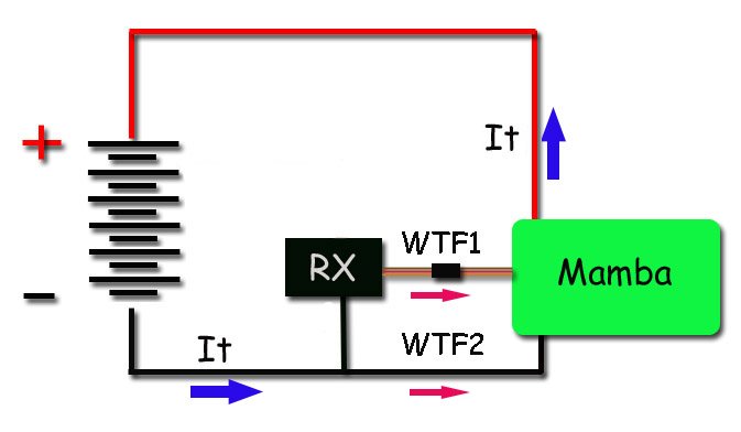
When the ESC is plugged in to the RX you create a series-parallel circuit that sends current to the Mamba...the two branches of the parallel circuit are represented with red arrows and labeled WTF1 and WTF2. :lol:
Total circuit current (for the Mamba's current path) is still shown with a fat blue arrow.
Total circuit current (for the Mamba's current path) is still shown with a fat blue arrow.
Attachments
Last edited:
Put it all together in the grand scheme of things and you get this...
It's basically the same thing that happens when you try to send too much current through a set of Tamiya connectors. The poor quality connection causes high resistance, which, when hit with a bit too much current, gets hot and melts.
It's basically the same thing that happens when you try to send too much current through a set of Tamiya connectors. The poor quality connection causes high resistance, which, when hit with a bit too much current, gets hot and melts.
Attachments
Last edited:
LOL!! thats great jia
microgoat
I wanna be Dave
So now, with a receiver pack, everything's hunky-dory. What's your PayPal addy, looks like I owe you five bucks :lol:
What I don't get is why it's okay to get 6 volts from a seperate receiver pack, but 6 volts from the main pack isn't kosher at all. There's still a potential voltage there. All I've changed is where I'm getting the voltage from. It's coming in through the same plug. Me feel not smart :-(
What I don't get is why it's okay to get 6 volts from a seperate receiver pack, but 6 volts from the main pack isn't kosher at all. There's still a potential voltage there. All I've changed is where I'm getting the voltage from. It's coming in through the same plug. Me feel not smart :-(
My assumption is that you are no longer sharing a common ground between everything. JIA made my head hurt too.
Stu,
Check out the attachment in post #28. If you look, the negative lead on the servo wire provides an alternate path for current flow (for the Mamba) from negative on the battery to positive on batt. This alternate path is through WTF1.
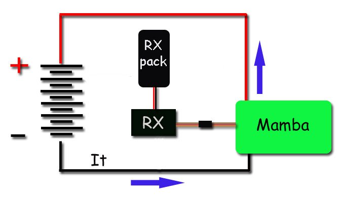
By switching to a RX pack you've eliminated the series-parallel voltage divider...see below.
Now any current drawn by the Mamba from the main batt pack (the fat blue arrows...It) isn't inadvertently pulled through the RX and the servo leads.
Check out the attachment in post #28. If you look, the negative lead on the servo wire provides an alternate path for current flow (for the Mamba) from negative on the battery to positive on batt. This alternate path is through WTF1.
By switching to a RX pack you've eliminated the series-parallel voltage divider...see below.
Now any current drawn by the Mamba from the main batt pack (the fat blue arrows...It) isn't inadvertently pulled through the RX and the servo leads.
Attachments
Last edited:
microgoat
I wanna be Dave
I'm buggered if I can figure it out. I'll take your word for it :lol:
slobin3d
I'm a stupid C U N T!
since there is nothin to stop power going through the rx negative side of the mamba it draws as many amps as possible even though its still 6 volts off the main pack. by putting the seperate rx pack in instead if the the main pack you break that connection between the common grounds hence shutting down the flow if current. you were lucky that the servo connector was the link point it could have easily been the rx itself.
microgoat
I wanna be Dave
I wasn't thinking of the negative lead of the receiver connection as a current-bearing circuit. Obviously I overlooked the possibility. I wonder if a diode or a cap in there would eliminate the need for an Rx pack?
slobin3d
I'm a stupid C U N T!
but then no power would flow thru the circut ever
what you need is a regulatore that fixes the amperage
what you need is a regulatore that fixes the amperage
microgoat
I wanna be Dave
Apparently what I need is a receiver pack :lol:
slobin3d
I'm a stupid C U N T!
like I said ^^^slobin3d said:goat i have a 5 cell flat pack you can have if you want it 1200mah
you could just cut the neg wire from the mamba as well. run signal only and you can go back to tapping 5 cells off the main pack.
Similar threads
- Replies
- 3
- Views
- 2K
- Replies
- 7
- Views
- 674