| |||||||
Loading
 |
| | LinkBack | Thread Tools | Display Modes |
| |||||||
 |
| | LinkBack | Thread Tools | Display Modes |
| | #1 |
| Quarry Creeper Join Date: Aug 2014 Location: holland
Posts: 253
|
YEAH!! There she is. After all lot of discussions (mostly with myself) I’ve decided to go for a Wraith kit. (And so did my buddy therefor there are two boxes in the pic.) 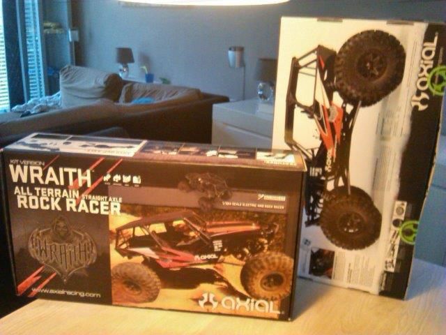 I committed to wait with the build till after graduating for my Bachelor grade (Thŕt will start an itch, thrust me!) Now with that in the pocket let’s start the build. 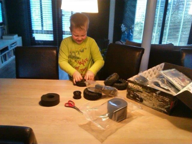 First priority: keep up with my 7yr-old son…. (“You don’t need those tyres yet, do you, dad?”) 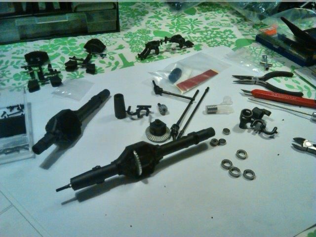 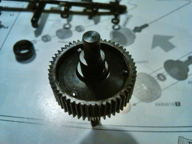 Found a bit of casting residu on the gears of the central transmission. Nothing a bit of sandpaper won’t cure. 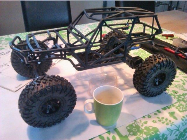 …to get a feel for the size…. |
| |  |
| Sponsored Links | |
| | #2 |
| Quarry Creeper Join Date: Aug 2014 Location: holland
Posts: 253
|
And the first upgrades/modifications/ not sticking to the plan: 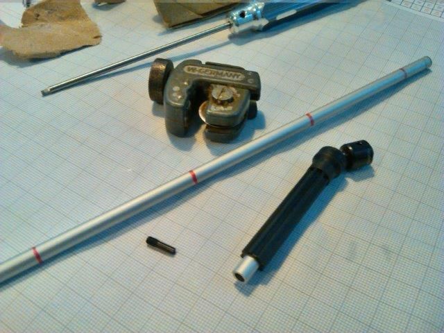 6mm aluminium tubes inside the driveshaft. 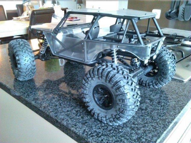 Close the doors and open the hood. 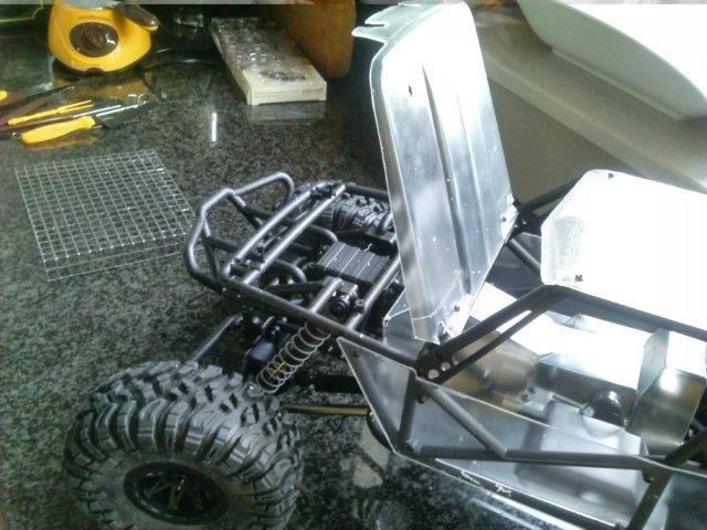 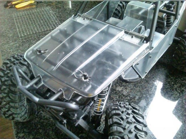 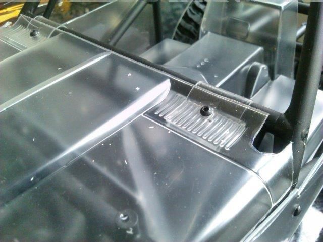 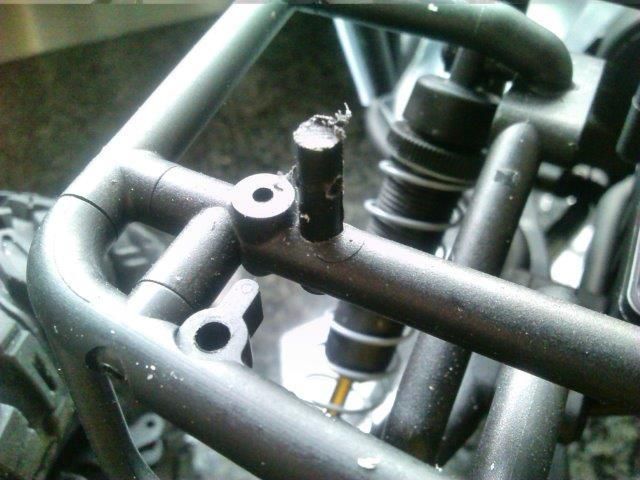 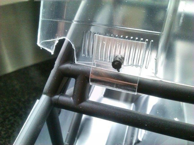 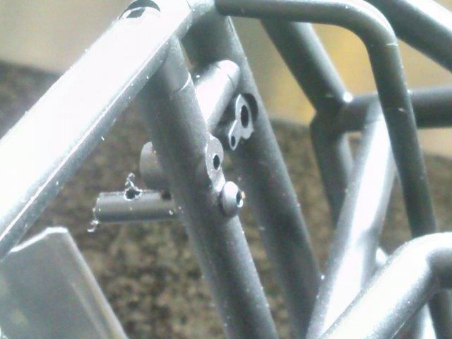 Made the hinches of some leftover body material and screws. Made the ‘nuts’ from pieces of parts tree rod. Took a 2mm drill and drilled the centre of the rod, sliced it to 3mm pieces and screwed them on (through the body). The ‘clip-poles’ are also of parts tree rod material. Drilled (I think) a 2,5mm hole though the chassis tube. And 5mm from the top till halfway. Screwed into the pole from the bottom. |
| |  |
| | #3 |
| Quarry Creeper Join Date: Aug 2014 Location: holland
Posts: 253
|
Drath and dubble drath; did my saw just fall into the back of the chassis? 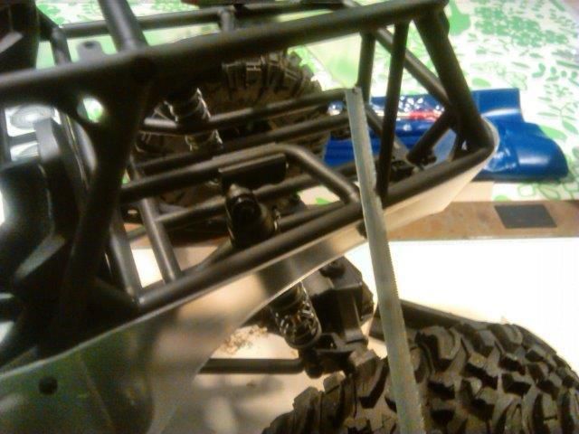 Now with the leftovers of the (also attacked) roof frame I made new C-columns. 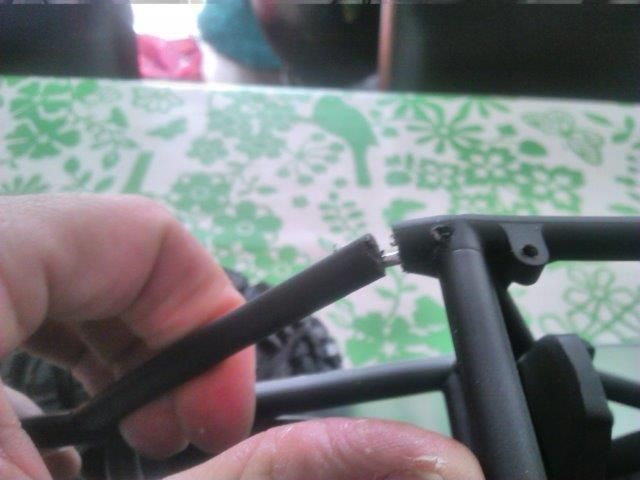 On the left side; pretty nice. With a steel rod inside for fixture. Right side didn’t work out a planned. Skipped ‘looks’ in favour of ‘function’. 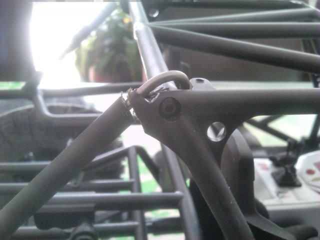 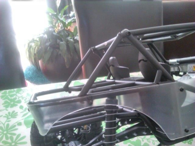 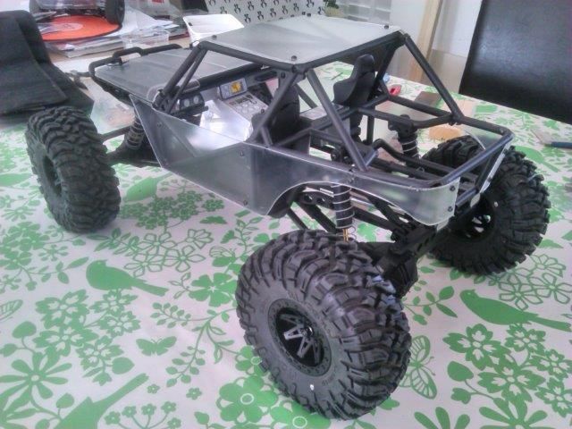 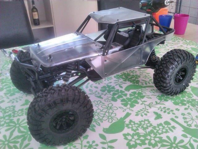 |
| |  |
| | #4 |
| Quarry Creeper Join Date: Aug 2014 Location: holland
Posts: 253
|
Thinking of paint After attempt # 2658 I decided on a colour scheme and a name. 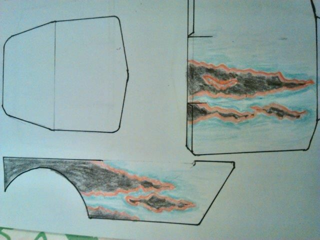 And with a lot of youtube, a low budget airbrush and a homemade compressor I got to work Let’s tape! 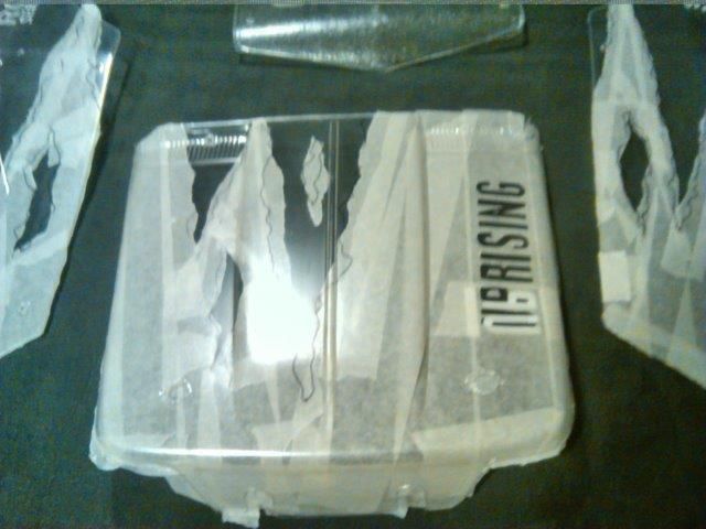 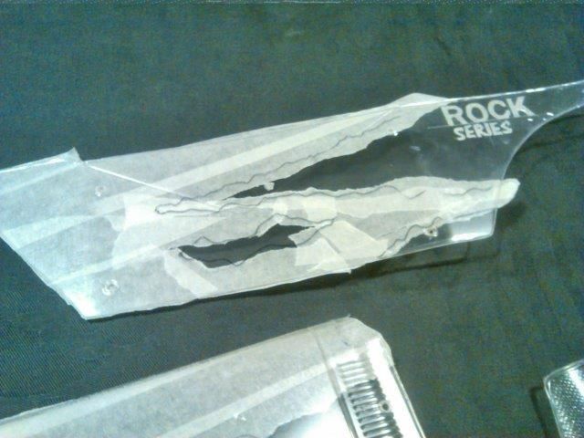 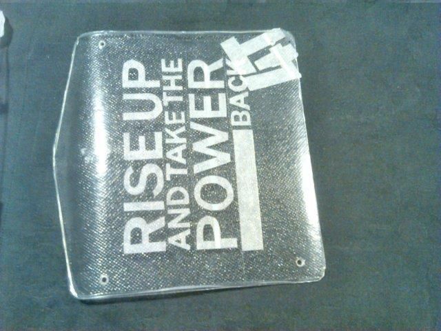 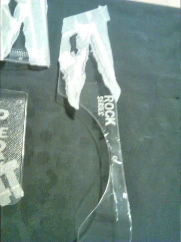 Darkest colour first; here’s black 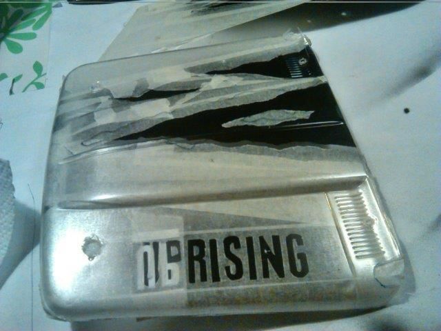 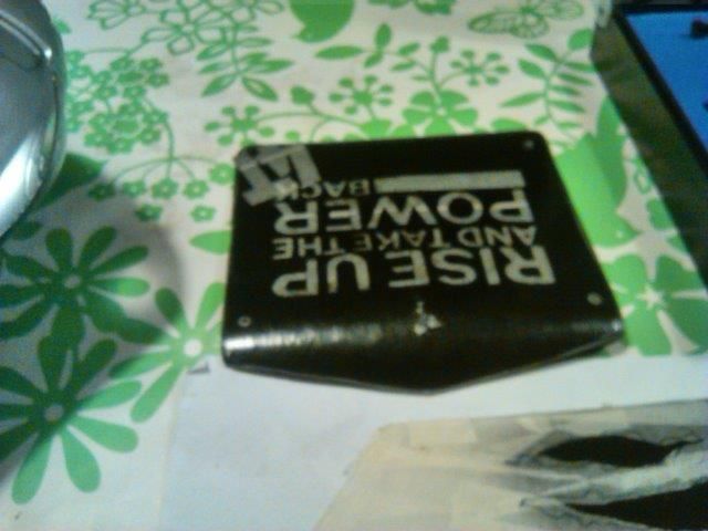 Then the red:   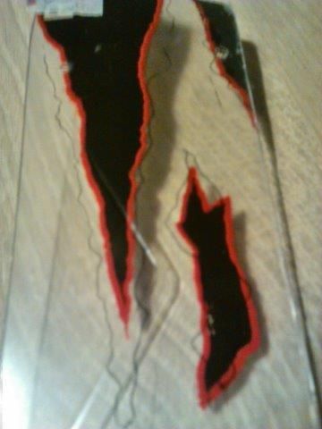 I didn’t find the exact youtube link again but I used a trick from ‘Hemistorm’. This guy does some awesome rc paintjobs. Check out his channel if you’re interested. No affiliation other than; he’s Dutch too. The trick was to tear up some paper tape lengthwise and use that to mask parts of the body. After painting it results in a torn up edge in the paint. As you can see I outlined the black with red. To have both edges follow the same profile I had to use the same torn up tape twice. Tricky to say the least, but it turned out brilliant (for my standards) Then a light blue edge fading to white. 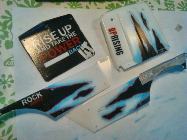 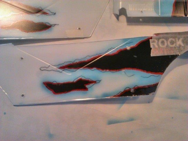 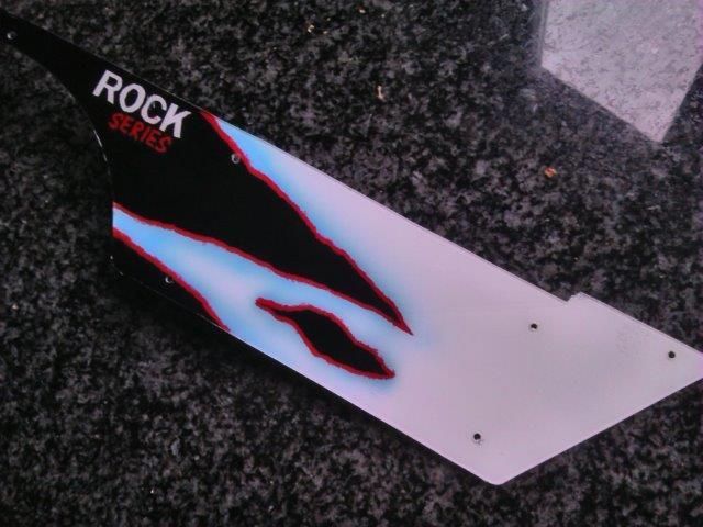   For the grill I taped in a piece of mosquito maze, sprayed black over it. Removed the maze and sprayed silver. 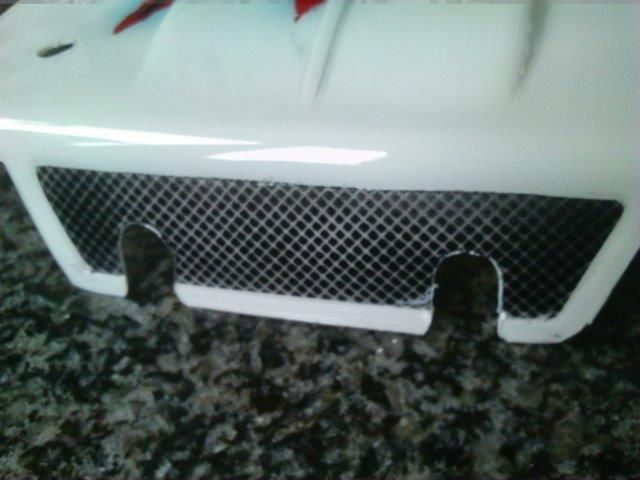 By no means perfect, but I’m happy with the result: 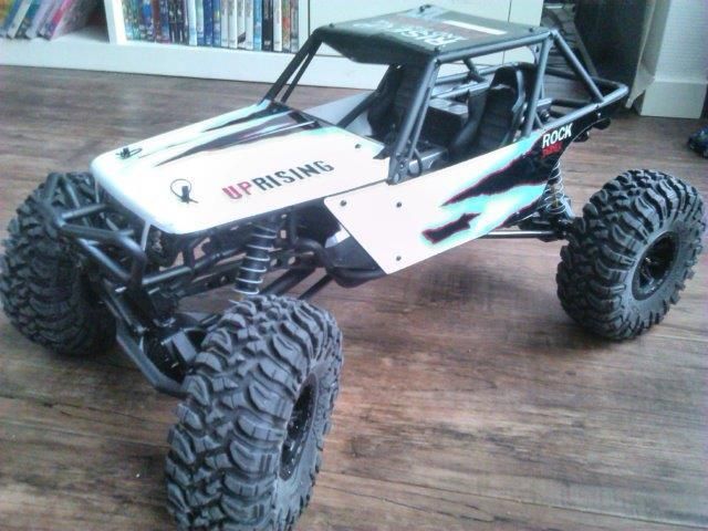 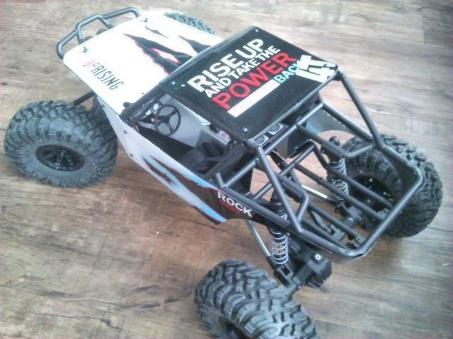 |
| |  |
| | #5 |
| Quarry Creeper Join Date: Aug 2014 Location: holland
Posts: 253
|
Electronics arrived No penlites in the transmitter 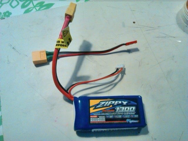  Where to start?? 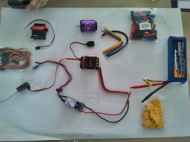 Top to bottom, left to right • Servo (TS 910) • Motor (HK XK3560-3200, 2 pole sensored) • Motor leads and connectors (motor on the skidplate ESC mounted on/in the tube frame) • Servo lead extensions (for BEC connection) • Trackstar 120A ESC • Zippy 3S (5000mAh) • Receiver (with Trackstar TS4G, which is actually a Radiolink RC4G, equipped with gyro) • Hobbyking 20A bec Servo horn hitting the chassis: 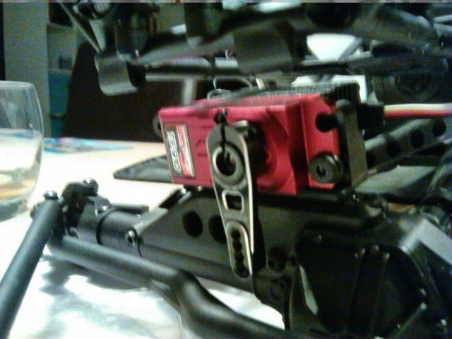 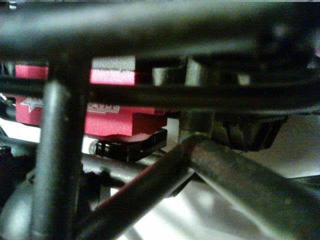 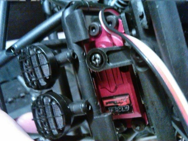 Made a new mounting plate to solve this: 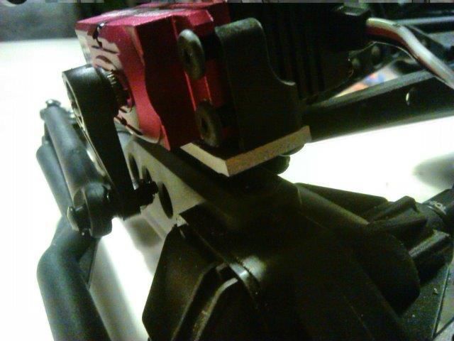 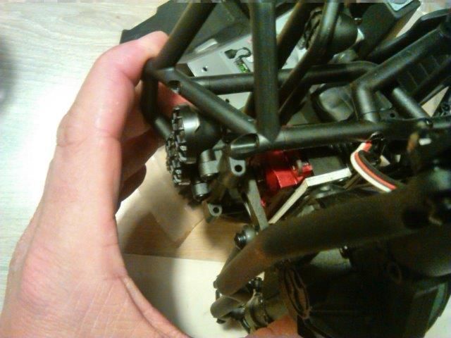 ESC mounting I took a 25mm (1”) aluminium L-profile mounted it across the chassis. The battery will be placed under the hood so the space between the seats is available for the ESC 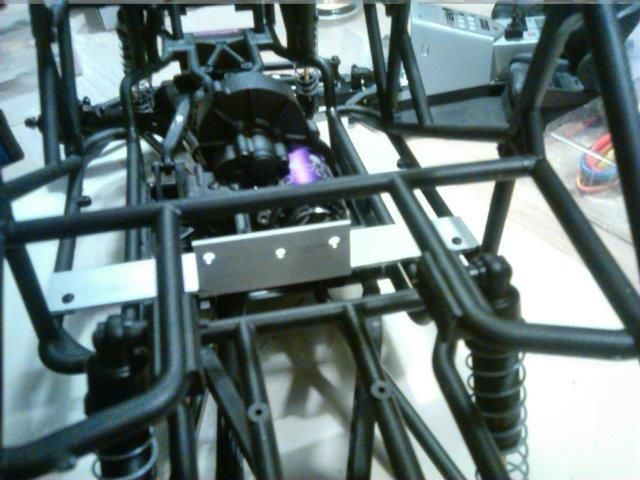 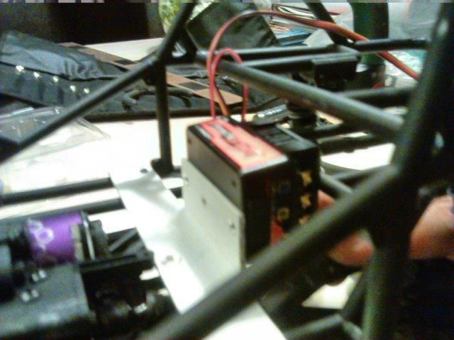 (recently, a little wiser, I found what headaches the wiring is gonna bring) In order to incorporate a BEC I made a Y-lead out of two servo lead extensions. The result resembles the second wiring diagram in the ‘beginners-topic’ without cutting or soldering and no ‘lose ends’. 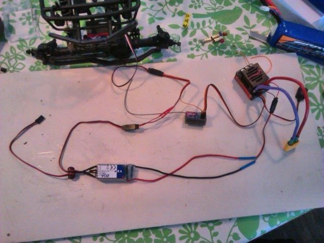 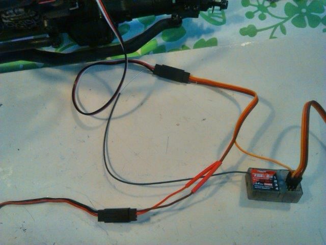 I also made a plug connection on the ‘feed’side of the BEC. 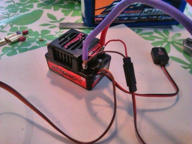 Last edited by wouterb; 05-04-2015 at 05:07 AM. |
| |  |
| | #6 |
| Quarry Creeper Join Date: Aug 2014 Location: holland
Posts: 253
|
Here’s a cardboard mock-up of the receiverbox that houses the RX and the BEC. 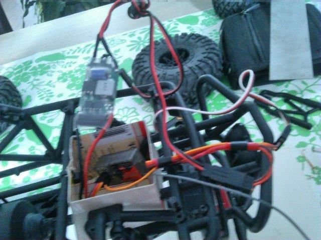 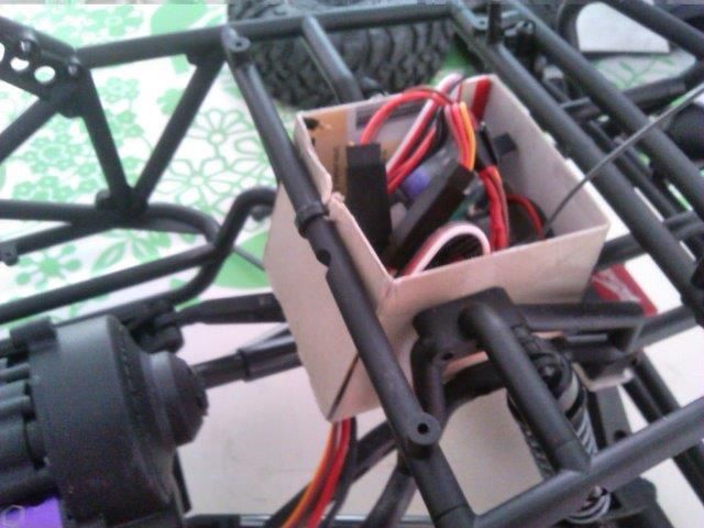 The throttle lead (to the ESC) is short, too short actually. It is plugged in but too tight for comfort. Rest of the wiring is fine…well… it fits. It’s probably way oversized but that’s my newbee ‘let’s-be-save’- attitude. (8AWG and 5mm plugs) 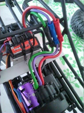 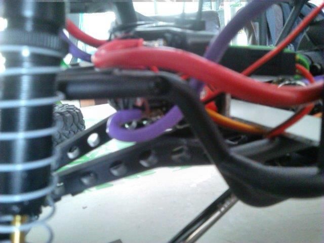 This is where I am now. I did fit the battery. She has had here shakedown. But there are still things to solve. • Building a battery compartment and receiverbox; • Improving ESC mounting; • Receiver needs to be mounted securely because of the gyro inside; • Light set has to be mounted; • Making brackets to raise the shock mounts and lower the car; • Get a winch …. And….and… (you get the point) Overall it has been a thrill building it. (My son is less happy because upgrading his ride has lowered on the priority list. But hey; It‘s his car that got me hooked in the first place) Like I said; this is where I am now. I’ll try and keep you updated. Tips and tricks are welcomed. |
| |  |
| | #7 |
| Quarry Creeper Join Date: Aug 2014 Location: holland
Posts: 253
|
Well, ‘Uprising’ has survived her Shakedown. And it is plenty fast. Faster than I expected anyway. I still have to glue the wheels so I used a set of monster truck tires found in a friends junk pile. I was not happy with the electronics placement, so took it all out. The ESC between the seats seemed like a good plan, but the wiring was a biatch and looked crap. Also, as mentioned the throttle lead was (too) short. Forgot to take pictures of the end result but the ESC moved back a little, now sits between the back shock mounts. The bracket used in the first attempt now houses the BEC and RX. They are taped and ti-ripped. I see possibilities to waterproof (balloon-style) in this location. Not sure about the BEC as it is equipped with a heat sink, that probably has a function…. 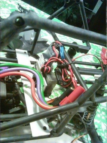 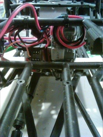 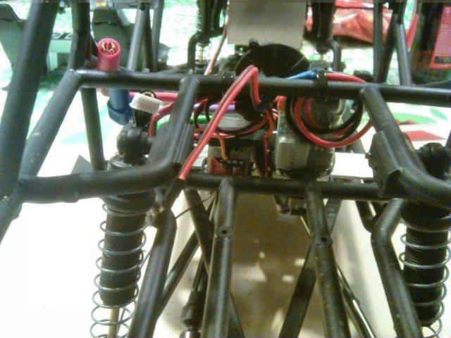 With all electronics nice and close together all wires are way too long…. I’ll get to fixing that. Also not in the pictures yet, the stainless battery tray under the hood. Fancier than intended but it does the job. Relocating current equipment leaves plenty of room under the hood for a future winch and light controller. Damn, this is getting addictive… |
| |  |
| | #8 |
| Newbie Join Date: Mar 2015 Location: long island
Posts: 2
|
looks like it is all coming together. I like the idea of the shock mounts to lower the center of gravity. I moved my battery up front and a friend of mine had slightly smaller then stock shocks that i threw on and my wraith crawls so much better now.
|
| |  |
| | #9 |
| Quarry Creeper Join Date: Aug 2014 Location: holland
Posts: 253
| thnx. Tonight I decided to try and glue up the tires to the rims. So I 1) Punctured the tires. 2) Got myself a tube of CA glue and a bottle of rubbing alcohol. 3) Checked a couple of youtube tutorials. Let’s do this. 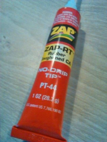 I started at the inside of the first rim (inner side first so a f…-up wouldn’t be that obvious). Glue should bond in seconds… it didn’t. Even after half an hour I could peel of the tire fairly easy. 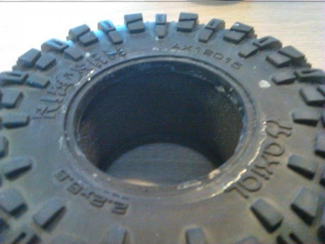 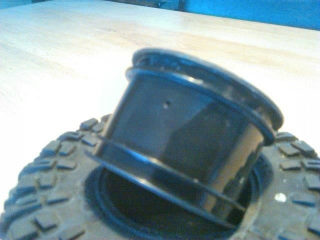 I guess I should have brought some sandpaper. Also my buddy recommended ‘brake cleaner’ and offered to bring it over to see how that would work. We went strolling the internet for advice and ended up at a webshop selling non branded beadlocks…..  For under €40 (around $42) per set (2 rims, 2 tires) I couldn’t lose so I went for it. On close inspection it looks like ‘Topcad 2.2 8-spokes’. Which is good, they fit the Wraith. 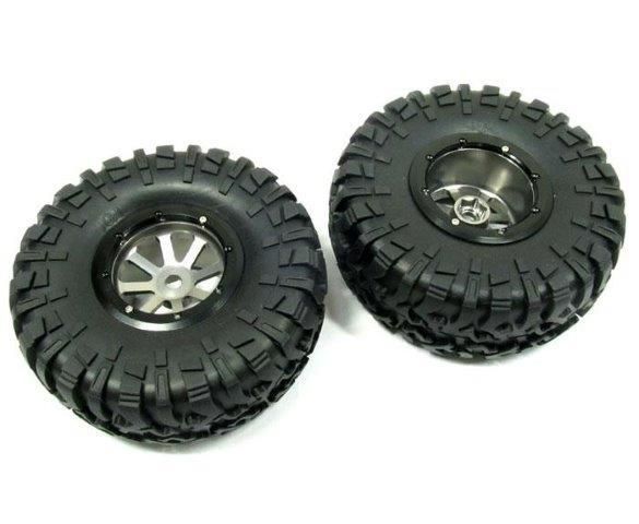 I have no clue about the quality of the tires. I do have the R35 ripsaws from the kit so if the Topcad tires proof to be rubbish they might be used in a couple of a parking lot/ bashing/ drift sessions. Anyone with experience on these wheel/tire combo? Anyway hope to get them early next week so the truck can taste the sand and mud in our local forest next weekend. |
| |  |
| | #10 |
| Rock Stacker Join Date: Jun 2014 Location: uk
Posts: 71
|
Looks good! Liking those wheels! Do you have a link or website name cheers
|
| |  |
| | #11 |
| I wanna be Dave Join Date: Sep 2011 Location: Douglassville, PA
Posts: 4,227
|
I've had the wheels bolted to my Wraith, they fit perfectly. Watch the little philips screws, they strip easy..i had to find a screwdriver with just the right profile and it worked like a charm. I would swap those tires over right away - ripsaws are darn good tires. |
| |  |
| | #12 | |
| Quarry Creeper Join Date: Aug 2014 Location: holland
Posts: 253
| Quote:
Nothing fancy, just had a bad feeling about glueing tires to even less fancy rims. So I want for cheap beadlocks. Tires werd a bonus.  Last edited by wouterb; 05-10-2015 at 01:35 AM. | |
| |  |
| | #13 |
| Quarry Creeper Join Date: Aug 2014 Location: holland
Posts: 253
|
Well okay then: Wheel are in! (Impressive pile but I have to give have of it away for my buddies ride) 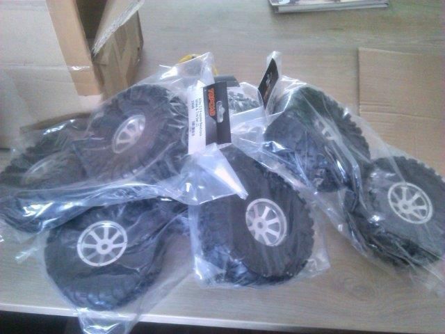 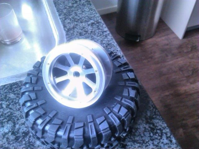 As expected they are Topcads. They look fit for the purpose. Added bonus: Topcad tires feel as soft as soft as the R35s. 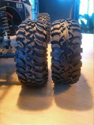  Treat pattern is less deep. Wonder if they will hold up in mud and sand compared to the ripsaws. 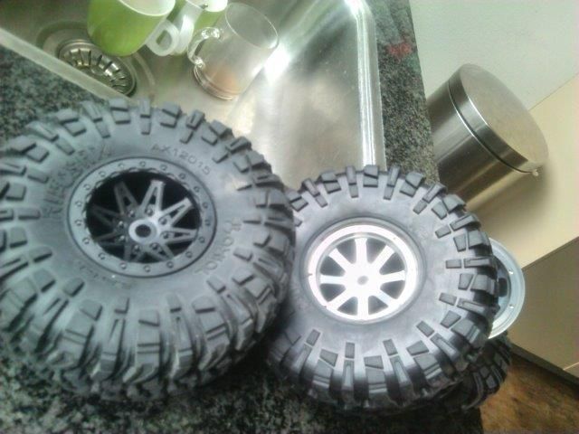 Lol. Pattern on the wall of the tire is a perfect Ripsaw rip-off 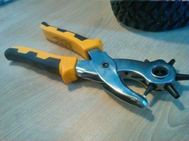 Punctured the ripsaws and started mounting them. 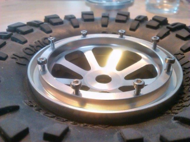 On one side of one of the rims I found a bug. Hex screws fell into the rim without rotating. This will not hold a bead ring. I used the fishing line trick. 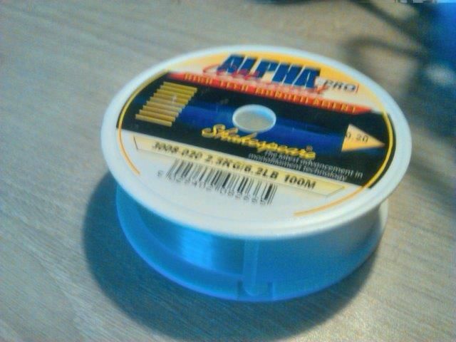 Basically I put a one (or two, if needed) treads of fishing line in the hole and then insert the hex screw. Worked like a charm. Didn’t come loose in the first couple of runs. (incl. jumps, slides, binds and scrapes) 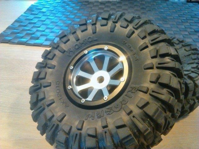 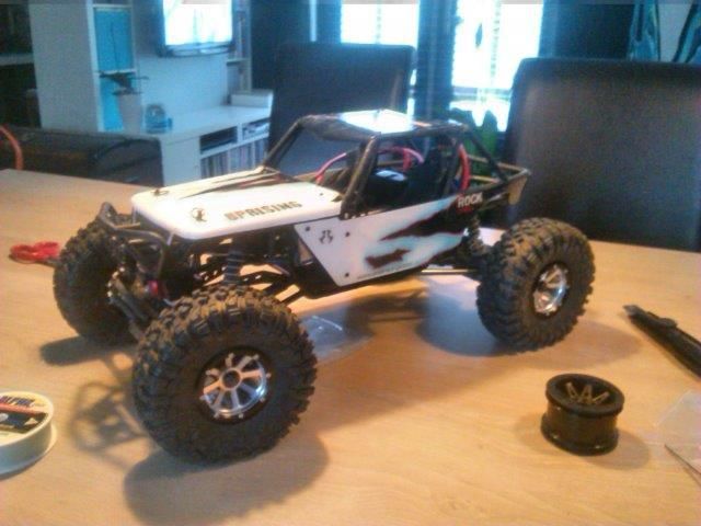 They’re looking great BTW Collected a lot of rubber to choose from in a short time ;) 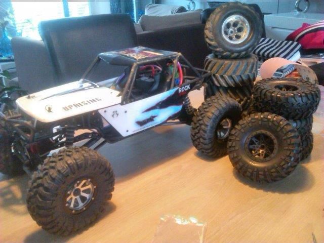 I did strip the standard plastic servo horn. So I replaced it with an aluminium version I had bought for just this occasion. * 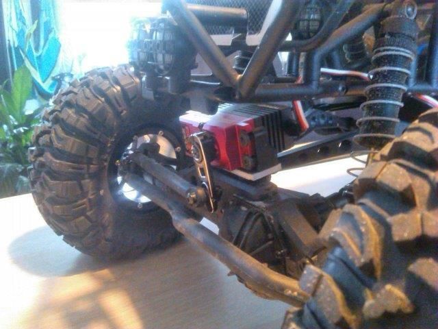 *Meanwhile I updated the trunk. I put in a bottom plate to mount the ESC. 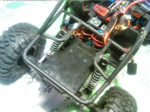 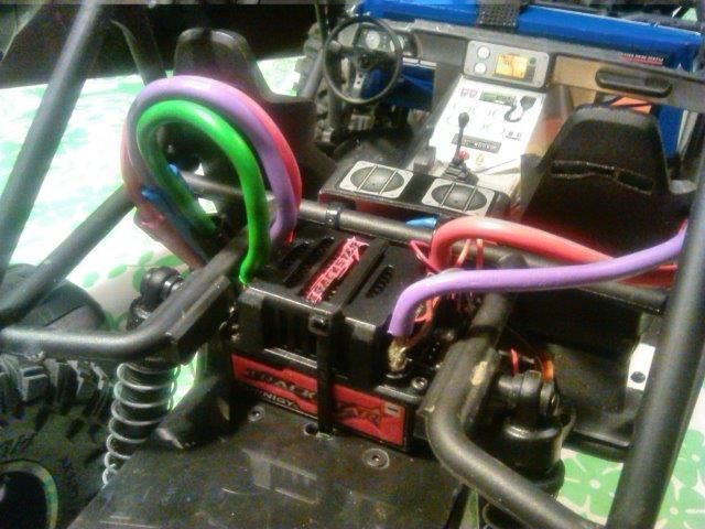 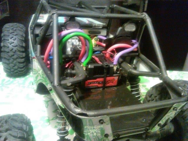 Also made (have made) a battery tray to house the 5000 mAh 3s. Plug comes from under the passenger dash. 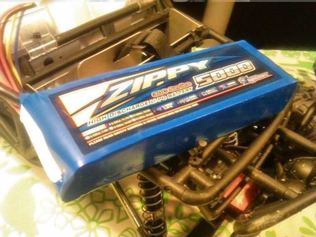 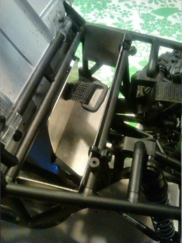 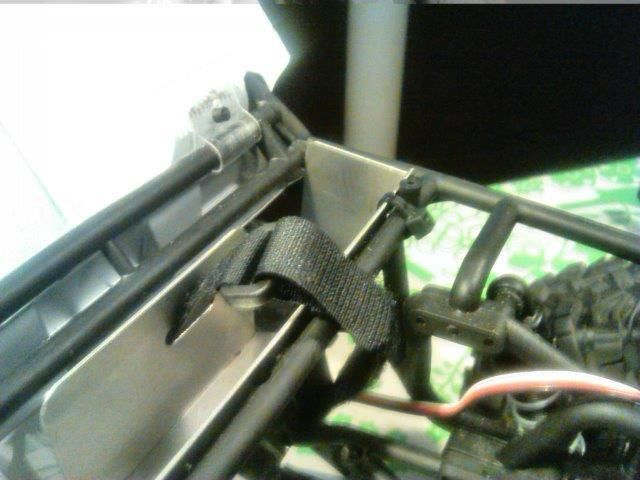 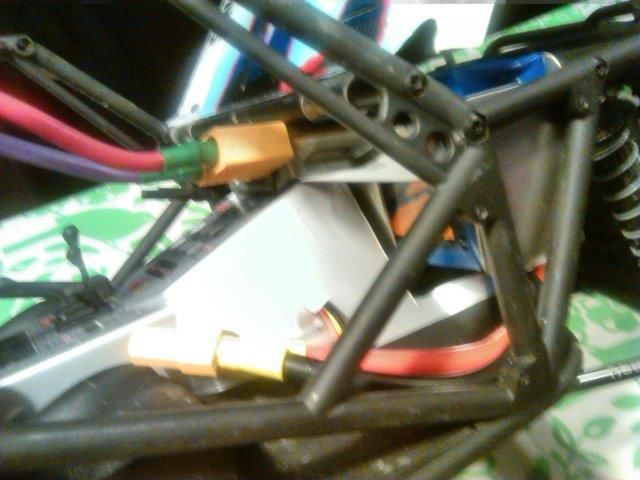 Ready to rumble!  Last edited by wouterb; 05-12-2015 at 03:33 AM. |
| |  |
| | #14 |
| Quarry Creeper Join Date: Aug 2014 Location: holland
Posts: 253
| |
| |  |
| | #15 |
| Custom Carbon Fiber  Join Date: Oct 2007 Location: Connecticut :(
Posts: 4,501
|  That just looks badd ass sitting like that. .......... What wheels and tires are those? |
| |  |
| | #16 |
| Quarry Creeper Join Date: Aug 2014 Location: holland
Posts: 253
| 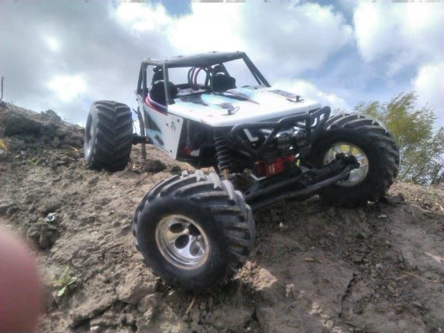 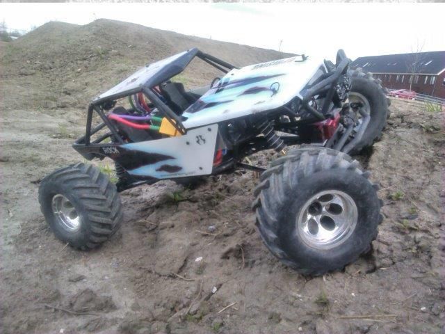 They even performed reasonably well drifting on solid dirt and sand (low traction). By no means is it fast enough to go truly Foff style. Tires are taken of a low-budget monstertruck: http://www.conrad.de/ce/de/product/2...-RtR-27-MHz-AM  This (online) store is based in most european countries. Mostly electronics but the do have a fair amount of toygrade and hobygrade rc stuff. Including wheels and other general exchangable parts. Last edited by wouterb; 05-19-2015 at 12:21 AM. |
| |  |
| | #17 |
| Quarry Creeper Join Date: Aug 2014 Location: holland
Posts: 253
|
Not invincible When I was out ploughing the forest floor last weekend I think I might have hit something. A broken rod end tells me so. 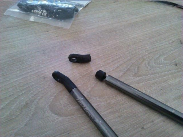 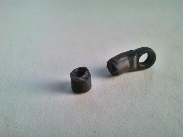 Not the biggest issue ever; I brought the plastic links (provided with the kit) along so swapping them took about 10 minutes. 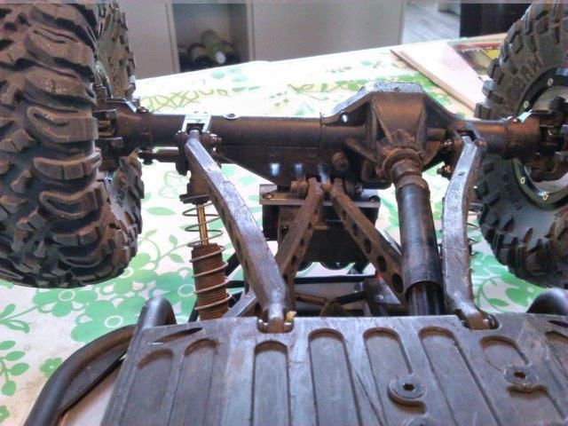 After a run with my son this weekend he managed to nosedive, flip over and landing rubber side down a couple of times. The obvious result: spaghetti links. Off to the LHS to get the materials to make my own links. I opted for the tread-in-tube method since it’s (relatively) simple, sturdy and cheap. • Traxxas #5347 • M4 thread rod • 6mm aluminium tube All this for less than €16 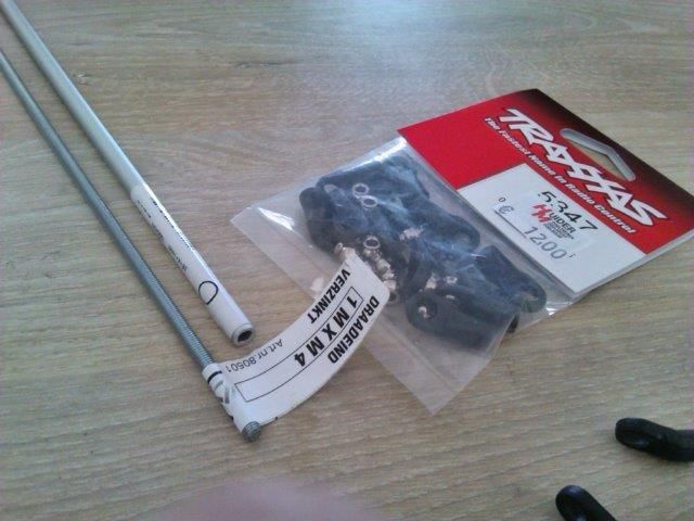 I just has to improvise a bending devise. Don’t laugh, I was in a form-follows-function mode. I placed the tread rod in the tube and started bending. 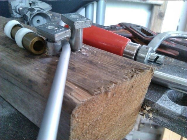 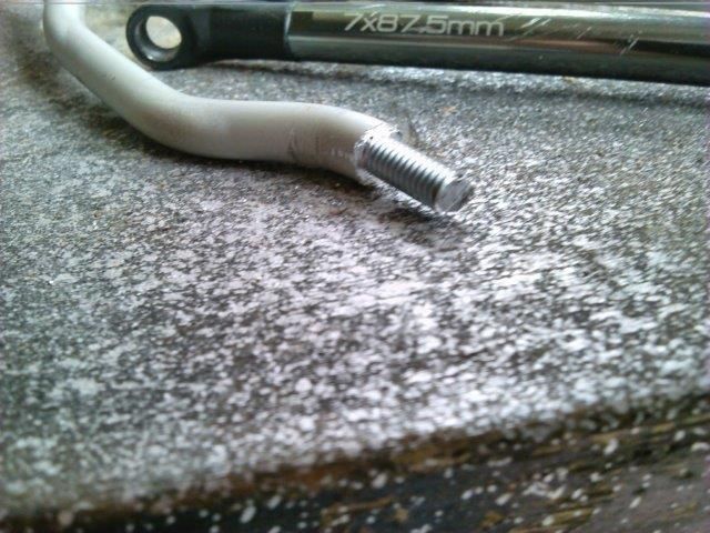 After bending the combined rod is sawn to length and aluminium shell is peeled back. Now the rod end can be mounted. It proved to be tricky to get the exact same length on all links but I managed to get them all within 1 mm of one another. 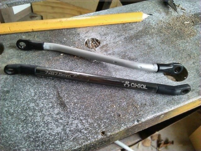 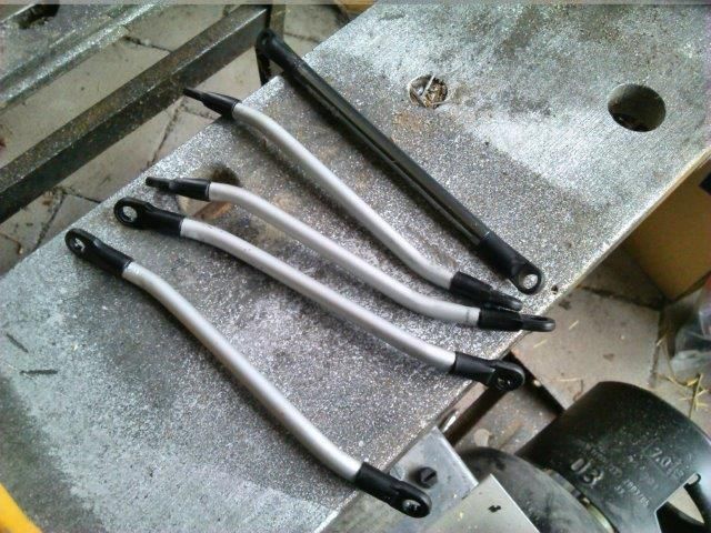 Mounting then was a breeze. Pretty happy with the result. 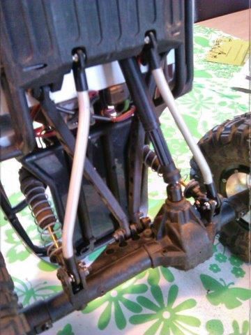 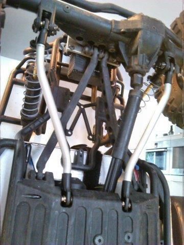 While I had half the suspension taken apart I took the opportunity to flip the suspension mounting brackets to lower the car and its COG. 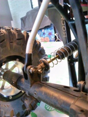 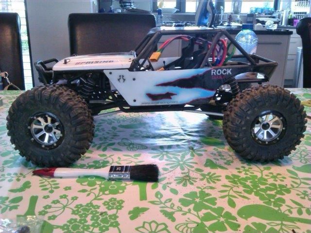 Next stop: take out and rebuild the shocks. They don’t operate as smooth as I would like. |
| |  |
| | #18 |
| Newbie Join Date: Jan 2015 Location: Cape Girardeau
Posts: 24
|
How's that servo holding up/performing?
|
| |  |
| | #19 |
| Quarry Creeper Join Date: Aug 2014 Location: holland
Posts: 253
| Servo is working just fine. When the rig is on its side in the rocks or a ditch, steering the servo actually lifts the car. Well, when on the right side anyway. On the left the plastic steering rod will bend and nothing happens. But that nog the servos fault.
|
| |  |
| | #20 |
| Quarry Creeper Join Date: Aug 2014 Location: holland
Posts: 253
| Let me answer that again: During some garden bashing/crawling I heard a grinding noise when steering. And steering to the left didn’t work apart from the noise. Shut down to investigate: 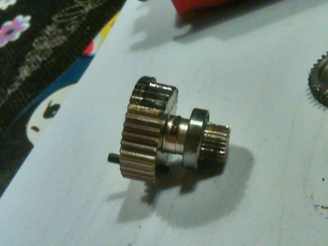 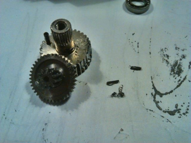 Spare part are on back order (of course) so let’s get creative. 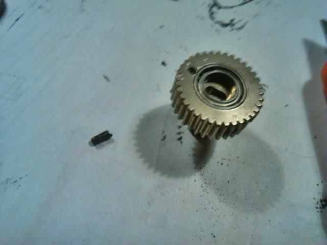 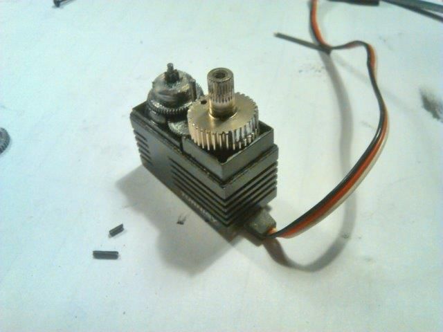 I took out the retaining pin of the final gear and mounted it 180 deg. rotated. So fresh teeth to mesh. Cheap fix for now. Now for the big ‘why?’ With the new links I also flipped the shock/link mounts and softened the springs, which lowered the rig significantly. 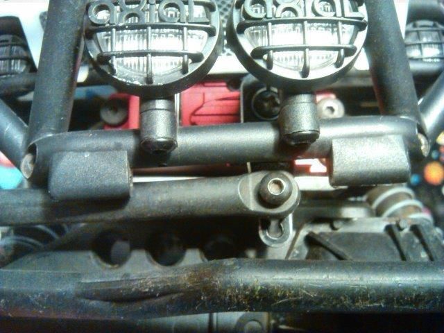 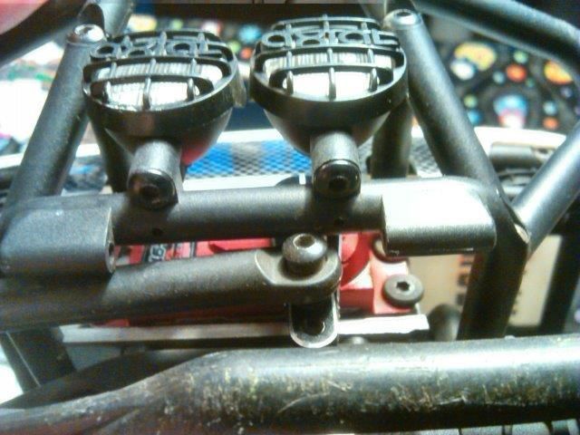 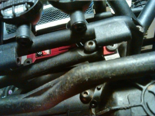 At full compression the screw of the top steering link sinks between the sway bar mounting points. Turning left in that situation will make it bind big time, too much for the gears anyway. As a solution for now I screwed the front shocks into the foremost mounting hole (they were mounted aft). This limits the maximum compression enough to keep the steering from binding. 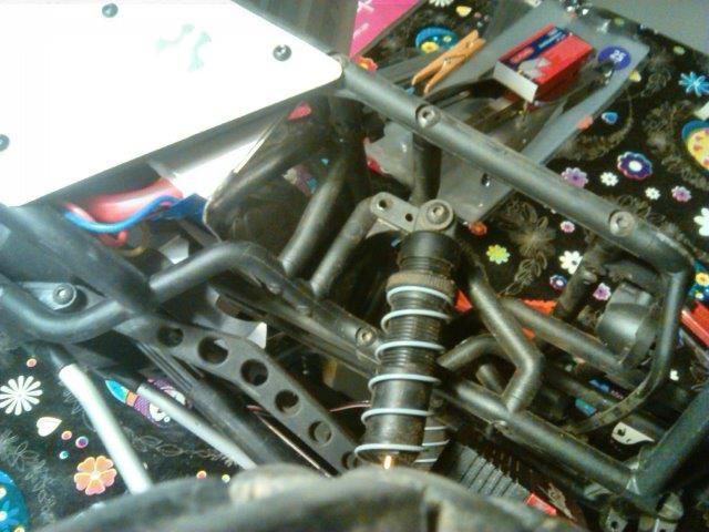 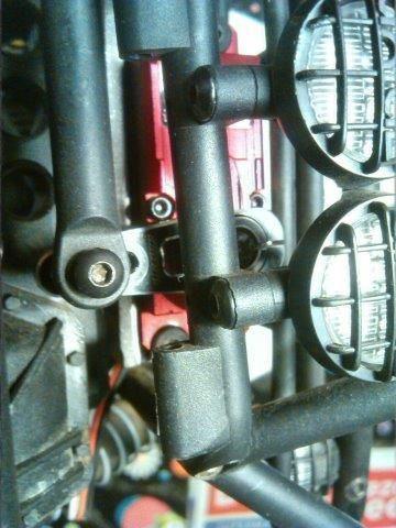 On the side I was planning to service the shocks as they were not operating as smooth as I would like. Do you guys think that an improvement can be made here? 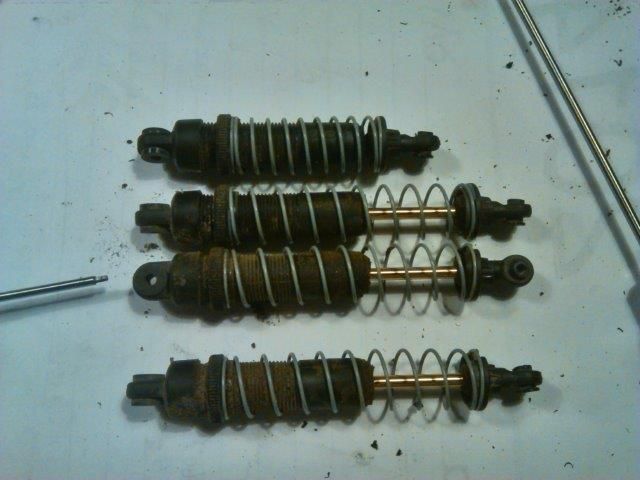 |
| |  |
 |
 The coming together of “Uprising” - Similar Threads
 | ||||
| Thread | Thread Starter | Forum | Replies | Last Post |
| Its coming! | norcallump | HPI Wheely King | 9 | 01-23-2010 12:08 AM |
| Ufc 68 Uprising | Kamikaze | Chit Chat | 16 | 03-03-2007 11:05 PM |
| |