| |
| |||||||
 |
| | LinkBack | Thread Tools | Display Modes |
 12-26-2007, 09:18 PM
| #1 |
| RCC Addict Join Date: Mar 2007 Location: St. Louis (High Ridge)
Posts: 1,279
|
trying to find the spacing between the upper and lower mounts. I need to try and mount one to a emaxx motor mount because the outrunner I got is too big to mesh so I am remote mounting it and trying to mount the pinion on an axle stub. Thanks. |

|  |
| Sponsored Links | |
| | |
|
12-27-2007, 06:36 AM
| #2 |
| Quarry Creeper Join Date: Dec 2004 Location: oxford
Posts: 274
|
DO you have any pics of what you are doing there ? I am a little un clear. I have alot of maxx stuff ,I might can help or atleast try any way!
|
|
| |
|
12-29-2007, 07:54 AM
| #3 |
| RCC Addict Join Date: Mar 2007 Location: St. Louis (High Ridge)
Posts: 1,279
|
Here are the axle carrier/knuckles on tower http://www3.towerhobbies.com/cgi-bin...?&I=LXEXG3&P=7 I know the middle hole is for bearings and the stub axle. I'm trying to find out how far apart (what the spacing is) between the left and right (as pictured) or top and bottom holes are. I have all the parts I colored, Including a 12t Pinion and 72t Spur but I haven't bought a knuckle or stub axle yet, not knowing if it would work, and not having any other need for it. 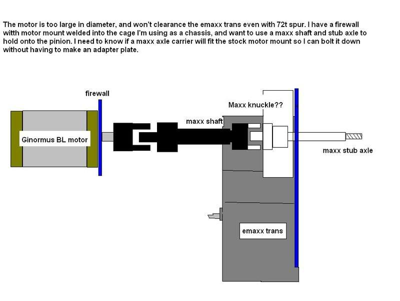 |
|
| |
|
12-29-2007, 04:55 PM
| #4 |
| Quarry Creeper Join Date: Nov 2007 Location: NH
Posts: 427
|
the 3.3 version is 45mm and the 2.5 version is 36mm measured at the pivot ball centers
|
|
| |
|
12-29-2007, 05:28 PM
| #5 |
| RCC Addict Join Date: Mar 2007 Location: St. Louis (High Ridge)
Posts: 1,279
|
ok, thanks. adapter plate it is. maybe I'll adapt to gd-600 and volt up. i think i've got enough room. |
|
| |
|
12-30-2007, 04:50 AM
| #6 |
| Quarry Creeper Join Date: Nov 2007 Location: NH
Posts: 427
|
Not sure If you have seen the knuckles but the 2.5 one may suit you better, it is flat on the front and rear, whereas the 3.3 one kinda bumps out some where the hex goes on
|
|
| |
|
12-30-2007, 04:51 AM
| #7 |
| Quarry Creeper Join Date: Nov 2007 Location: NH
Posts: 427
|
oh yeah make sure you post some pics I would like to see what you come up with
|
|
| |
|
12-30-2007, 08:05 AM
| #8 |
| RCC Addict Join Date: Mar 2007 Location: St. Louis (High Ridge)
Posts: 1,279
|
OK, thanks for that, I'll run to the LHS and try to find both to compare. if the 3.3 version is further apart, I may be able to file the face flat, and drill mounting holes on 25mm centers without even getting close to the pivot ball hole. I may go the GD route anyway seeing as how the motor I'm using can run fine on 5 to 6 lipo cells, and I'm currently using 2. and after all isn't volt up gear down the JRH motto? I'll throw a pic here, but most of it will go in the build thread joining the mid-sized party |
|
| |
|
12-30-2007, 06:50 PM
| #9 |
| owner, Holmes Hobbies LLC   Join Date: Nov 2004 Location: Volt up! Gear down!
Posts: 20,290
|
You will need to make an adapter to hold the driveshaft, and also get the stub axle turned down. I remember Kamikaze did a setup like that, but I cant find the thread.
|
|
| |
|
12-31-2007, 04:09 AM
| #10 |
| Quarry Creeper Join Date: Nov 2007 Location: NH
Posts: 427
|
If you need to turn the shaft down then the 3.3 version would be better. the stub shaft can be removed from the yoke for turning it down, the 2.5 version stub shaft/yoke are molded as one and do not come apart. with the need to have the shaft turned down, it may be easier to just have a small aluminum block made to to fit your stock motor mount then you won't have to make an adapter plate then adapt a knuckle to it,plus it might look alot more professional when its done
|
|
| |
|
12-31-2007, 07:36 AM
| #11 |
| RCC Addict Join Date: Mar 2007 Location: St. Louis (High Ridge)
Posts: 1,279
|
I had thought of boring out the pinion to 6mm and making a collar for it to strengthen the set screw, or maybe notching the face of it to ride on the drive pin which would also hold it in the carrier. just make a spacer and hold it against the drive pin with a wheel nut. or doing a combination by rilling out the pinion, then drilling an aluminum hex to fit the OD of the pinion. Alloy pinion, alloy hex, zip zap zoop with the welder, and there is a drive pin slotted pinion with 6mm ID Making a block Might work. I might also use some 1/2 inch conduit, weld that to a little plate, bolt up the plate and put 12mm OD bearings inside the conduit with a little shim action. I dunno. I ended up working yesterday, so nothing got done. Dang that work interfering with my "real" life. and I ran my gearing spreadsheet, and the GD-600 won't really get to a high enough ratio. even trying to push 4s lipo through the Mamba Max it would put me at 2.3 and 3.7 mph (1st and 2nd gears respectively) with an 18t pinion. here's the link in case anyone asks P1) instructions P2) spreadsheet P3) Gearing reference chart (i still need more reference numbers.) http://www.one18th.com/forums/showthread.php?t=46883 |
|
| |
|
01-18-2008, 04:39 PM
| #12 |
| RCC Addict Join Date: Mar 2007 Location: St. Louis (High Ridge)
Posts: 1,279
|
OK, finally got around to putting it together Pics will be in the build thread joining the mid-sized party |
|
| |
|
| |


 Linear Mode


