| |
| |||||||
 |
| | LinkBack | Thread Tools | Display Modes |
 08-02-2007, 11:35 AM
| #1 |
| Newbie Join Date: Dec 2006 Location: Toledo
Posts: 45
|
For quit a long time, I have been wanting to make a really scaled RC. And one of the things I wanted to do if I ever did make one was... Make a manual transmission like you see in cars today. And until yesterday I was on the site "www.howstuffworks.com" (I've been on their site before but never thought of using it for transmission stuff) and when I was done reading the article (it was on rotary engines) it made me think of the transmission.. Then the idea popped in my head to look for manual transmissions. After reading the pages, I finely understood all the mechanics of the 5-speed. Now then, I plan on making a Clutch (just for kicks), a 5 speed, and possibly a reverse (after everything is done) I am going to be using 1/10 pinions and spurs, but if I can find enough 1/18th scale pinions/spurs I will use those so they take up less space. I already found a 6 pack of pinions that I could get I (probably 1/10th) http://www2.towerhobbies.com/cgi-bin...&I=LXEX34&P=ML Are Robinson Racing pinions any good do you guys know? And I want to use a spur with the holes in the middle, like this one so that I can use the holes for the "dog teeth" to slide into. (But if I find a good set without them, I'll just drill my own holes) http://www2.towerhobbies.com/cgi-bin...?&I=LXPA05&P=7 Also, I will need to get the correct spur for the correct pinion, if I don't the centers of the spurs wont match up on one rod. (Say like one set of gears has 100 teeth in total, I would need ever one of the other 4 gears to have 100 teeth too. Like, pinion for gear set one are 20/80 set 2 would be 30/70 and so on, as long as the total is the same as the rest of the gears the centers will not be a problem.) Illustrations: A different color means a different part. Sometimes parts will overlay other parts, and the outline of the other part will be visual. Clutch: I messed up on the clutch, the red rod should go and continue to the tranny, not the black...but you get the idea 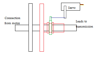 Transmission (Made by HowStuffWorks.com): Shifting Animations: Green line = 1&2 shift fork Blue line = 3&4 shift fork Red line = 5&R shift fork  (Remember, the shifter has a mounting point at which it can move, that's why every thing is backwards.) I would love some feedback/advice/links to spurs/pinions (1/18 would be great) Last edited by Charger; 08-02-2007 at 11:42 AM. |

|  |
| Sponsored Links | |
| | |
|
08-02-2007, 11:48 AM
| #2 |
| 20K Club   Join Date: Jul 2004 Location: Sending illegals home one Hayabusa at a time.
Posts: 22,981
|
Cool, yes. The only thing I have to say is....................good luck. I would guess in the range of a couple hundred hours of work, atleast. And the parts would have to be super small if you wanted to use it in a scaler unless maybe a 1/6th. |
|
| |
|
08-02-2007, 11:49 AM
| #3 |
| Quarry Creeper Join Date: Mar 2007 Location: Syracuse
Posts: 384
|
You gots alot of work ahead of you! I hope you get it finnished. As for gears, RR products are top notch. |
|
| |
|
08-02-2007, 11:49 AM
| #4 |
| Newbie Join Date: Dec 2006 Location: Toledo
Posts: 45
|
Electric, And yes I know I wouldn't need to make a reverse... Just be fun to have it I guess. (Also, I said I might possibly make it after everything is done and runs good...not top priority) EDIT: Cslax, could you give a link to their website or something? Thanks. |
|
| |
|
08-02-2007, 11:54 AM
| #5 |
| I wanna be Dave Join Date: May 2006 Location: Arlington, VA
Posts: 3,377
|
Yeah, that thing is going to be a monster, way to big for 1/10 scale. Maybe 1:6 but I'd say more like 1:4. Sounds fun to try though, and if your going and doing all that, may as well have the reverse also. One thing I forsee is having to do some tooth work on the gears so they engage smoother.
|
|
| |
|
08-02-2007, 11:55 AM
| #6 |
| I wanna be Dave Join Date: May 2006 Location: Arlington, VA
Posts: 3,377
|
Robinson Racing Products has been around since the 80's that I know of and their products are top shelf.
|
|
| |
|
08-02-2007, 11:56 AM
| #7 |
| RCC Addict Join Date: Mar 2007 Location: MS Gulf Coast
Posts: 1,949
|
Yes I have thought about this before. Maybe a four speed to save room. Remember that to get four wheel drive it will need a t-case. This would be great for scale though b/c it would place the motor in the front of the rig over the front diff. In doing this it will also require an offset front diff and a centered rear diff. It would actually be a replica of a 1:1 when set up properly.
|
|
| |
|
08-02-2007, 12:00 PM
| #8 | |
| Newbie Join Date: Dec 2006 Location: Toledo
Posts: 45
| Quote:
Also, I was thinking... I've seen some REALLY big pinions, maybe I could use those instead of spur... It would save a hell of a lot of room. Only thing is, the ratios might be bit too much for the motor. And it would mean more work because I would have to cut, and drill... and if I messed that up.... I have to wait till I get another set. | |
|
| |
|
08-02-2007, 12:06 PM
| #9 | |
| Newbie Join Date: Dec 2006 Location: Toledo
Posts: 45
| Quote:
| |
|
| |
|
08-02-2007, 12:10 PM
| #10 |
| I had the hottest girlfriend at the MSD Nats Join Date: Dec 2006 Location: Hecho en Tejas
Posts: 2,399
|
how fast do you plan on going? oooor how slooooow! i am definately watching this one.
|
|
| |
|
08-02-2007, 12:17 PM
| #11 | |
| Newbie Join Date: Dec 2006 Location: Toledo
Posts: 45
| Quote:
Also, the gears are not going to sliding in and out, unmeshing or anything like that. | |
|
| |
|
08-02-2007, 12:21 PM
| #12 | |
| Newbie Join Date: Dec 2006 Location: Toledo
Posts: 45
| Quote:
| |
|
| |
|
08-02-2007, 12:21 PM
| #13 |
| I wanna be Dave Join Date: May 2006 Location: Arlington, VA
Posts: 3,377
|
For size your better off using pinions and pinions, although you may not get a very broad range of gearing. Not like using spur's anyway.
|
|
| |
|
08-02-2007, 12:43 PM
| #14 |
| Rock Crawler  Join Date: Apr 2006 Location: Salem, Orcrc
Posts: 756
|
this sounds wicked, good luck. im sure there are spurs or othe gears small enough, you just have to look hard enough |
|
| |
|
08-02-2007, 12:48 PM
| #15 |
| I wanna be Dave Join Date: May 2006 Location: Arlington, VA
Posts: 3,377
|
What are you going to use for a case, somthing scale looking?
|
|
| |
|
08-02-2007, 12:58 PM
| #16 |
| Newbie Join Date: Dec 2006 Location: Toledo
Posts: 45
|
The case is probably going to be basic at first... once things get running smoothly I'll make modifications later to make it scale looking. (If I get bored that is Also, I have gathered what gears I will be able to use. O I U N T P P U U T T 12+35=47 First gear 13+34=47 14+33=47 15+32=47 2 gear 16+31=47 17+30=47 18+29=47 3 gear 19+28=47 20+27=47 21+26=47 4 gear 22+25=47 23+24=47 +++++++ 24+23=47 5th gear 25+22=47 26+21=47 Yay! Just need to figure out the R gears now. Last edited by Charger; 08-02-2007 at 01:06 PM. |
|
| |
|
08-02-2007, 01:10 PM
| #17 |
| Quarry Creeper Join Date: Jul 2007 Location: Sierra Vista, Arizona
Posts: 271
|
Ok, I may be wrong on this, but I am not totally sure... but I think I know from experience with real transmissions with my dad.... Back when cars first started coming out, they had straight cut gears. And the transmissions would grind alot. Thats where the term "gear grinder" came from. Now days, gears are not striaght cut. I beielve they are helical cut, like on real car differentials. there may be another term but anyway. They dont cut them straight anymore. They have them cut diagonally. This is so the gears can engage with each other without grinding. On RC tranny's, like for nitro vehicles, the tranny's have mostly straight cut gears. But this is because out RC tranny's use a different method of shift. Most RC tranny's use clutches and weights to engage the other gears, and thus making it ****. Now on a Tamiya High Lift tranny, I am not totally sure how that works, but it appears to me like straight cuts that a slid into place by a shift fork. But like I said, I dont know. those little things could be on a totally different system of processes that I dont know about. If you are going to make this tranny just like a car tranny, you will need a complitcated system to get it to shift like a car. And that would be UP Down Over Down UP Over.... etc.. To do that with a servo, you would need a servo to move the shifter over, as well as a seperate servo to move this up. unless of course you had a micro motor on tracks with a servo attachech to it, or maybe an accuator(the thing that pushes a little arm outwards)on tracks. Second of all, you wouldnt be able to use straight cut gears. it would grind them all the time, and that would eat all of the gears alive, especially having them that small. You would need them to be helical or curve cut, and that would be hard, expensive, and probably wouldnt turn out so good. If you think i just copied this from somewhere, or you think I am BS'ing, Im not. I have learned this from countless hours of car shows, Modern Marvels on the History Channel, and many many many articles on the internet, as well as experience with my dad in the garage. I really hope this helps you man. I dont mean to rain on your parade, I dont think this thing will work for you. Hell, maybe you could just add and extra 2 speeds to a Tamiya 3 speed. I dont know. But good luck, and I hope this helped you some. Last edited by Krawlin; 08-02-2007 at 01:14 PM. |
|
| |
|
08-02-2007, 01:13 PM
| #18 |
| Rock Crawler Join Date: Oct 2006 Location: Tacoma
Posts: 699
|
too much math................head............spinning  |
|
| |
|
08-02-2007, 01:20 PM
| #19 |
| Newbie Join Date: Dec 2006 Location: Toledo
Posts: 45
|
I was a little worried about the gears on real transmissions being angled, but I figured that's because those gears are spinning at much higher RPMs and are put to more stress then the ones that I will be using. Also, I figured some numbers for the reverse gears. First number is the input, second the idle gear, third the output. 12+12+23=47 13+12+22=47 14+12+21=47 15+12+20=47 16+12+19=47 I'm thinking one of the first 3 sets might do it, maybe 13+12+22. EDIT: Also, on the method of shifting via remote. It is going to have 2 servos, one to shift it up and down, and one to shift it left to right. I will designate one Analog stick(forget what they call em) for shifting, and I will have to make a shift gate also. Last edited by Charger; 08-02-2007 at 01:27 PM. |
|
| |
|
08-02-2007, 01:32 PM
| #20 | |
| Quarry Creeper Join Date: Jul 2007 Location: Sierra Vista, Arizona
Posts: 271
| Quote:
| |
|
| |
|
| |


 Linear Mode


