| |
| |||||||
 |
| | LinkBack | Thread Tools | Display Modes |
 04-27-2008, 10:20 PM
| #1 |
| RCC Addict Join Date: Feb 2008 Location: Hiatus..sutiaH
Posts: 1,620
|
Hopefully I do not get flamed for this but I have to ask. I have a CC MM coming, as well as a motor soon hopefully. I already have the CC BEC. I have been reviewing the install diagrams from the BEC and just wanted to make sure I do it right. Is there a definitive wiring diagram that I can use to do a one time job. One time meaning all at once. Meaning done right. I have wired many R/C's before, but never added a BEC. JRH, do you happen to have anything that could help me? I just want to be careful as I have heard a lot of problems lately about mis-wiring of people's setups. Thank you for the help in advance guys. Jon Last edited by JohnRobHolmes; 01-27-2011 at 08:11 AM. |

|  |
| Sponsored Links | |
| | |
|
04-27-2008, 10:36 PM
| #2 |
| TEAM MODERATOR   Join Date: May 2004 Location: Tennessee
Posts: 10,855
|
Everything hooks the same as any other RC. When you install the BEC,pull the red wire from the ESC's receiver plug. If you leave that wire in there,it'll fry the BEC inside the ESC. Might need that BEC if you decide to put the ESC in a basher of some sort. I like to just pull the wire and shrink tube it back for future use. You can just cut it,but then you'll have to fix the wire if you wanna use it again. After the red wire is pulled,plug the ESC's receiver plug into the receiver. There are various ways to do this,but make a tap off the battery wires on the ESC. The red and black wires on the input side of the BEC will plug in there. Then,plug the output side of the BEC into the receiver. |
|
| |
|
04-28-2008, 12:51 AM
| #3 |
| Rock Crawler Join Date: Dec 2007 Location: Ventura, Ca
Posts: 528
|
This is how I do mine. This way the voltage and amps to the servo is not going through the RX. The bec on the ESC powers the rx at 4.8 volts or what ever the bec is on the esc. I get less glitching and no problems burning rx from all the amps to the servo. And I can set my CC Bec to whatever voltage I want without overvolting the rx. Its a crude drawing, but it works. 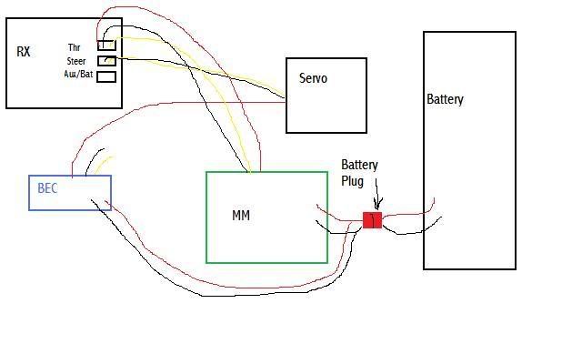 |
|
| |
|
04-28-2008, 08:48 AM
| #4 |
| RCC Addict Join Date: Aug 2006 Location: trying to find out what a TVuPer is.....
Posts: 1,851
|
On the back of the packaging that the CC BEC comes in there is a diagram that shows exactly what you asking, check it out. p!nK |
|
| |
|
04-28-2008, 10:36 AM
| #5 | |
| RCC Addict Join Date: Feb 2008 Location: Hiatus..sutiaH
Posts: 1,620
| Quote:
Thanks for the diagram Rocksmith. That was what I was hoping for. I don't want to chalk this one up to laziness as I know the diagram is on the BEC package. Just needed a little help. | |
|
| |
|
04-28-2008, 11:05 AM
| #6 |
| owner, Holmes Hobbies LLC  Join Date: Nov 2004 Location: Volt up! Gear down!
Posts: 20,290
|
I would use rocksmith's diagram, but he left out the negative wire from the CC BEC to the servo. The only lead going from RX to servo is the signal.
|
|
| |
|
04-28-2008, 11:08 AM
| #7 |
| owner, Holmes Hobbies LLC Join Date: Nov 2004 Location: Volt up! Gear down!
Posts: 20,290
|
Here is a pic somebody sent me, shows pretty clearly what is going on. The second pic is how the harness is made to isolate the servo power. |
|
| |
|
04-28-2008, 01:08 PM
| #8 | |
| RCC Addict Join Date: Feb 2008 Location: Hiatus..sutiaH
Posts: 1,620
| Quote:
| |
|
| |
|
04-28-2008, 01:24 PM
| #9 |
| owner, Holmes Hobbies LLC Join Date: Nov 2004 Location: Volt up! Gear down!
Posts: 20,290
|
Right, ignore the other motor and servo if you wouldn't be using them.
|
|
| |
|
04-28-2008, 01:55 PM
| #10 |
| Rock Crawler Join Date: Apr 2007 Location: APPLE VALLEY,CALIFORNIA
Posts: 985
|
now i'm not very electrical savvy,but just to make it clear to me ....i wired mine the way it has on the BEC package. would the way rocksmith wired his be a BETTER way to wire it ?? what's the benefit if any to wiring it this way ?? thanks for the help ,i'm trying to learn as much as possible about the electronics side of building crawlers ...thanks again
|
|
| |
|
04-28-2008, 02:43 PM
| #11 |
| owner, Holmes Hobbies LLC Join Date: Nov 2004 Location: Volt up! Gear down!
Posts: 20,290
|
If you don't have any glitching you don't need to worry about it. Where issues arise with the Castle way is that large amp spikes can cause all kind of problems inside some RX's. The Berg 7 can handle them just fine, but most ground radios can't. Wiring like Rocksmith showed routes the amp draw around the RX, getting rid of the issue. |
|
| |
|
04-28-2008, 02:48 PM
| #12 |
| Rock Crawler Join Date: Jan 2008 Location: Arlington, TN
Posts: 624
|
John, would wiring like the cause the shuttin down prob im having to go away? Somethings not right????? HELP |
|
| |
|
04-28-2008, 02:51 PM
| #13 |
| owner, Holmes Hobbies LLC Join Date: Nov 2004 Location: Volt up! Gear down!
Posts: 20,290
|
It can't hurt.
|
|
| |
|
04-28-2008, 10:39 PM
| #14 |
| Rock Crawler Join Date: Jan 2008 Location: Arlington, TN
Posts: 624
|
Just wanted to say thanks to john, i wired it this way and all is good.  |
|
| |
|
07-25-2008, 01:00 PM
| #15 | |
| I wanna be Dave Join Date: Jun 2005 Location: KENNEWICK, WA
Posts: 2,513
| Quote:
| |
|
| |
|
07-25-2008, 01:22 PM
| #16 | |
| owner, Holmes Hobbies LLC Join Date: Nov 2004 Location: Volt up! Gear down!
Posts: 20,290
| Quote:
| |
|
| |
|
07-25-2008, 03:43 PM
| #17 |
| I wanna be Dave Join Date: Mar 2008 Location: Pacific Ocean
Posts: 2,342
|
So if I followed this correctly Rocksmith's diagram should actually look like this? 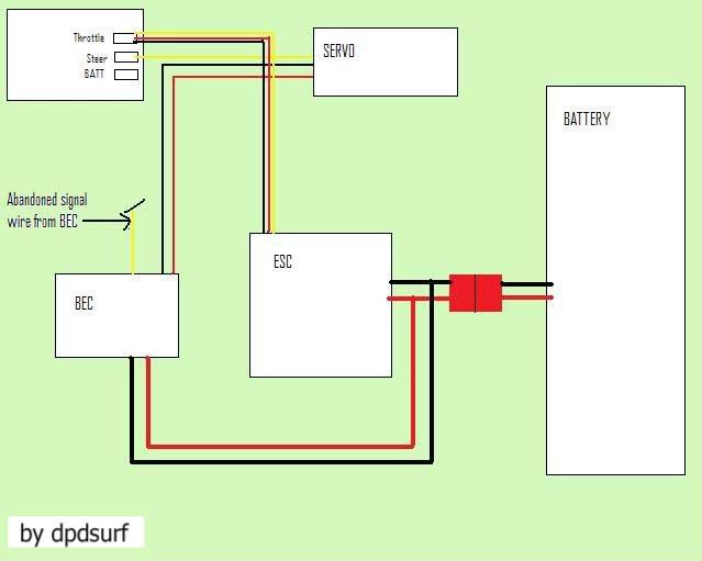 |
|
| |
|
07-25-2008, 09:27 PM
| #18 |
| owner, Holmes Hobbies LLC Join Date: Nov 2004 Location: Volt up! Gear down!
Posts: 20,290
|
Yes!
|
|
| |
|
08-09-2008, 07:56 AM
| #19 | |
| Quarry Creeper Join Date: Mar 2008 Location: san pancho, ca
Posts: 224
| Quote:
did you ever wire y our servo/ESC as in your diag? survey says? :-P | |
|
| |
|
08-18-2008, 10:13 AM
| #20 |
| Newbie Join Date: Jul 2008 Location: Hinckley, U.K.
Posts: 26
|
Electrics really isn't my forte, so would like to get this right. I have the CC MM, a CC Bec, the Cobalt 7T puller, and am wiring up as per diagram. I'm just a little confused on wiring up of the motor as i'm left with a black, red and a white lead on the MM with just 2 wires on the motor. Do I just ignore the white, and wire up the black and red??? Aplogies for this, Nitro background with RC's |
|
| |
|
| |


 Linear Mode


