| |
 08-15-2009, 04:38 AM
| #21 |
| Pebble Pounder Join Date: Aug 2008 Location: Spain
Posts: 103
|
Windscreen wipers  |

|  |
| Sponsored Links | |
| | |
|
08-15-2009, 07:00 AM
| #22 |
| Rock Stacker Join Date: Jul 2009 Location: So. Cal. - SanBernardino
Posts: 69
|
or in america we say windshield wipers. nice work clockworks! i got mine a few days ago and... you remember how the guy couldn't get it to work? you know the guy that sold it to me? well i installed the driver, plugged it in and nothing...:-( so i searched the internet for hours, i found a website with a video on how to set it up... but hey, you know that the whole "don't install the software before the drivers" is not true. i installed the software on my laptop a month ago and it still worked fine. i guess i got lucky! it was real cheap and i didn't even have to wait 20 days for it to ship. i will try to bind it with my other rx to see if that works. now i just have to look for a cheap if not free-ish pistol tx for the swap |
|
| |
|
08-15-2009, 08:20 AM
| #23 | ||
| Pebble Pounder Join Date: Aug 2008 Location: Spain
Posts: 103
| Quote:
Quote:
Waiting for your build....... | ||
|
| |
|
08-15-2009, 09:47 AM
| #24 |
| Pebble Pounder Join Date: May 2006 Location: Holland
Posts: 101
|
Great thread guys! I'm currently trying to stuff a gutted HK 4ch 2.4Ghz in an old JR Tx. Just like on your radio, the throttle and steering trim works by mechanically changing the original stance of the pot. However, this is not possible on the JR. So I need to add some external trim pots. How should I wire these up? Parallel on the 3 wires from the steering pot? And what value pots should I look at? The steering and throttle pots are around 5K, centering at 2.6K.  Secondly, the wire for the coaxial antenna came off. On the board there's a square marked 'Jack1', but it consists of four contact points. Any difference between them, or should I just pick the outermost?  Thanks for the help! Last edited by Galladon; 08-15-2009 at 09:53 AM. |
|
| |
|
08-15-2009, 04:48 PM
| #25 | |
| Rock Crawler Join Date: Feb 2008 Location: UK
Posts: 818
| Quote:
Glad you got the software working. I think I messed my desktop PC up by connecting the interface cable before I loaded the drivers. It works fine on my laptop. Have you re-calibrated the ESC to the new radio? The Tx that Carlos linked to is worth paying $20 for. It's a perfect fit. | |
|
| |
|
08-15-2009, 05:03 PM
| #26 | |
| Rock Crawler Join Date: Feb 2008 Location: UK
Posts: 818
| Quote:
I think that wiring another pot in parallel will work better as a trim, but I haven't tried it yet. It's on my list of things to do, hopefully I'll get time to try it tomorrow. That RF PCB looks the same as mine. The centre conductor of the antenna wire goes to the contact point on the right (3 o'clock position). The other 3 points are ground. The shield can go to any of them. Mine goes to the 12 o'clock and 9 o'clock positions. Good luck soldering the wire back on - I needed to use a 5x binocular magnifier just to see it clearly! | |
|
| |
|
08-15-2009, 05:04 PM
| #27 |
| Pebble Pounder Join Date: Aug 2008 Location: Spain
Posts: 103
|
Driver 1:(xp/7) PL-2303 USB to Serial Bridge (H, HX, X) Installshield Driver Setup Program Installer & Build date: 1.0.5.18 (20090723) Windows 98/ME Driver: v2.0.0.19 Windows 2000/XP/Server2003 (32 & 64-bit) WDM Driver: v2.0.9.122 Windows Vista/7/Server2008 (32 & 64-bit) WDF Driver: v3.3.5.122 NOTE: For Windows 7, please use RC build 7100 or above. http://www.prolific.com.tw/support/f...ler_v10518.zip Driver 2:(Vista) PL-2303 USB to Serial Bridge (H, HX, X) Installshield Driver Setup Program v2.0.0.19 for Win98SE/ME v2.0.2.1 for Win2K/XP/2003 (XP Logo Certified) For Prolific USB VID_067B&PID_2303 Only (for Mobile Phone, GPS, Modem, IrDA USB Serial Cable) http://lib.store.yahoo.net/lib/coold...l-adapters.zip |
|
| |
|
08-15-2009, 05:09 PM
| #28 | |
| Pebble Pounder Join Date: Aug 2008 Location: Spain
Posts: 103
| Quote:
I havent tested it yet, but it could work adding a pot from the middle contanct of the pot to the input on PCB. | |
|
| |
|
08-15-2009, 05:48 PM
| #29 |
| Rock Crawler Join Date: Feb 2008 Location: UK
Posts: 818
|
Playing the steering rotary switch yesterday, I noticed that the servo travel was quite limited. Had the same thing with my DX6i conversion, but not quite as bad. Problem is the limited rotation of the pot. The original stick pot goes down to about 800 ohms at each end. The wheel pot only drops to about 1500 ohms. This gives around half the steering travel that the original Tx had. Solution is to allow the pot to move more. There are 2 things limiting rotation - the sprung lever on the steeringwheel spindle catches the case, and the wheel has a limiting stop. I cut away part of the standoff that supports the pot assembly: 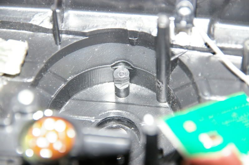 I also shaved a couple of millimetres off the lever: 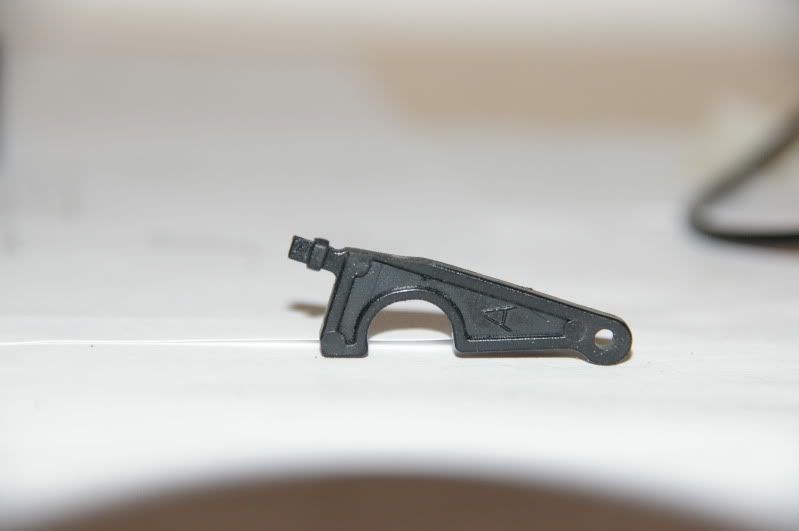 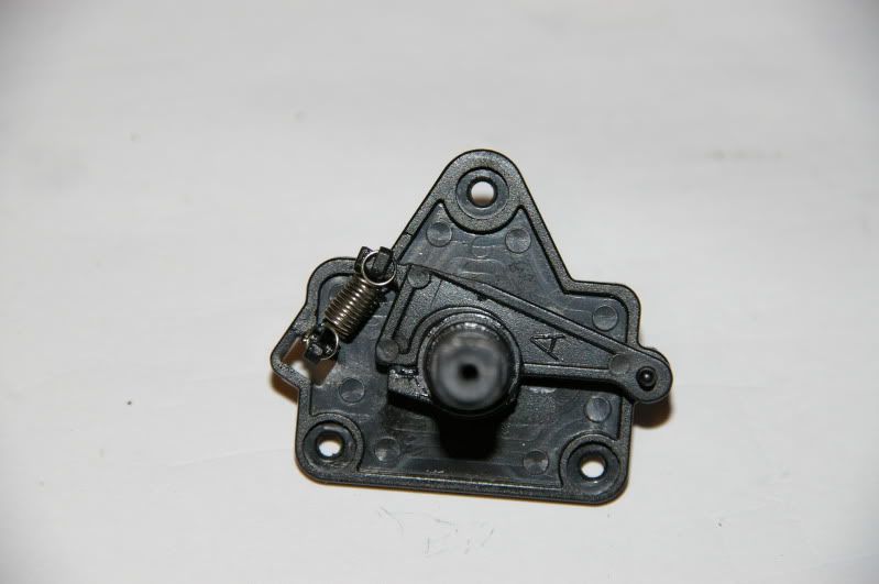 Without the wheel fitted, the pot now moves enough to push the cam/lever "over centre". I carefully trimmed away part of the limiting projection on the case that prevents the wheel turning full circle: 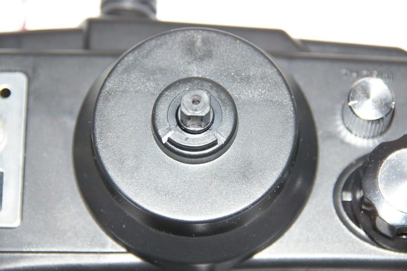 The pot now drops to around 1K, so I get around 90% of the original steering servo movement. It can be "overdriven" to 120%, so that should be enough |
|
| |
|
08-16-2009, 02:53 AM
| #30 |
| Pebble Pounder Join Date: Jul 2009 Location: Windsor, UK
Posts: 141
|
I'm a bit confused about using pots for winch, lights, dig etc. Isn't that exactly what people are using 2 and 3-pos switches for? the switches basically replicate servo travel on the rx end which is what most winches want, or digs, or gear shifters?
|
|
| |
|
08-16-2009, 04:16 AM
| #31 | |
| Rock Crawler Join Date: Feb 2008 Location: UK
Posts: 818
| Quote:
No harm in having a pot and a switch on the same channel - gives you the option to use whichever control method you need - as long as the pot doesn't get moved when you are using the switch. That would mess up the end points. I'm going to fit both on ch5. I don't have a use for ch5 yet. | |
|
| |
|
08-16-2009, 04:55 PM
| #32 |
| Rock Crawler Join Date: Feb 2008 Location: UK
Posts: 818
|
Time to start the wiring. I've decided on the switch layout: 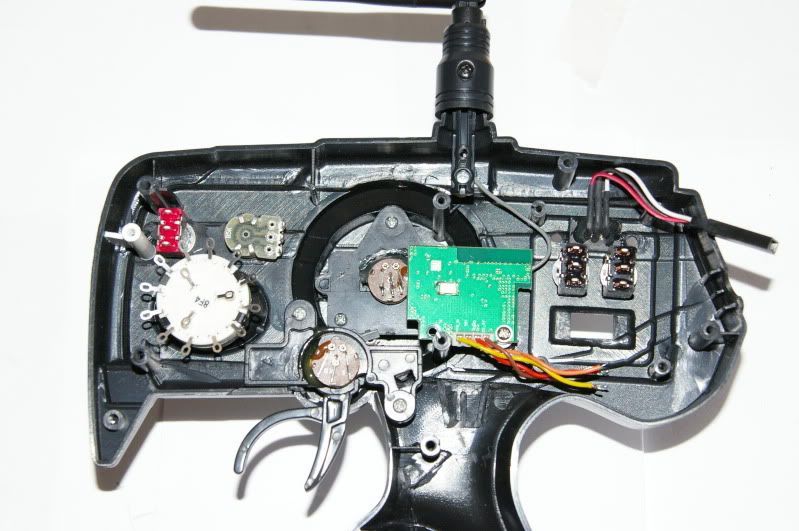 Wires and resistors added to the ch5 3-position switch and pot: 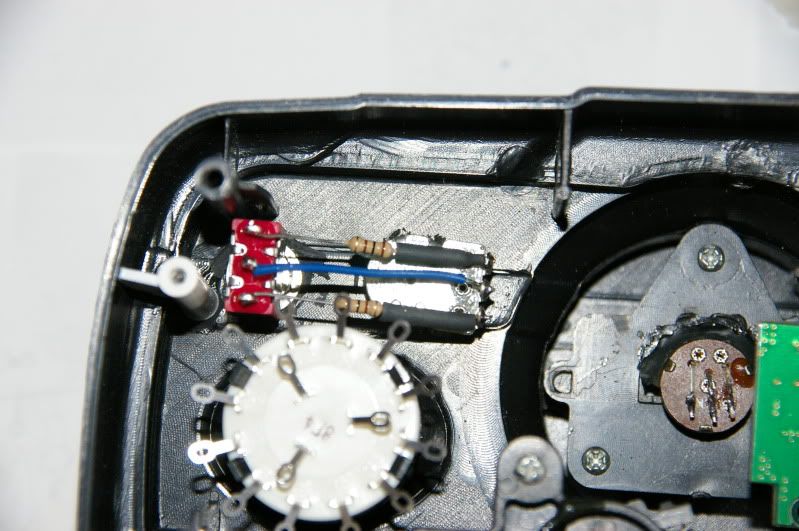 Wires added to the rotary steering switch: 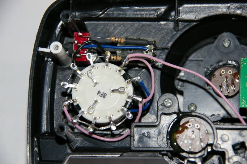 And the wires running down to the trimpot PCB: 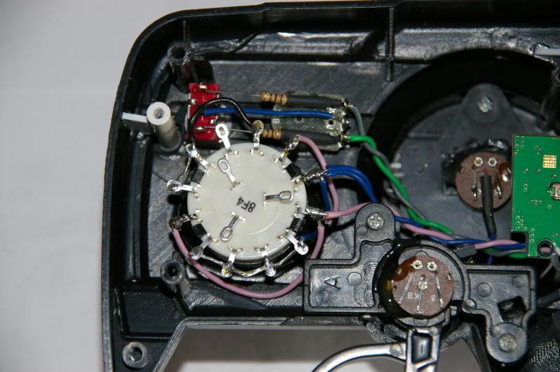 Wiring for the 2-position switches: 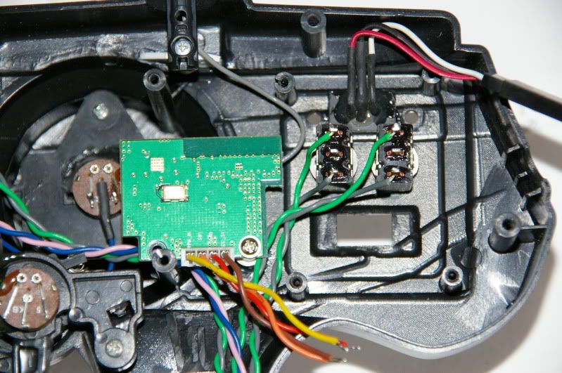 The power PCB fitted: 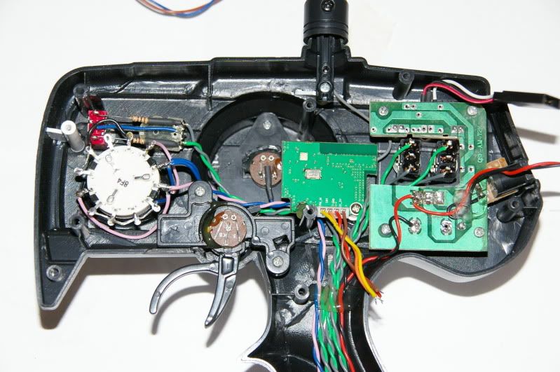 Connecting the main PCB wiring: 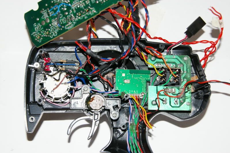 Because I'm fitting trims and EPA pots in the base, all the channels except ch2 (throttle) have wires running from the pots/switches down into the battery compartment. They will pick up the 5v and ground connections from the trims, so the red and black wires from the main PCB aren't used. I tied them back with a piece of heatshrink. PCB wiring completed: 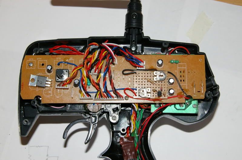 All that's left to do is make and fit the trimpot PCB in the battery bay, then I'll post the schematics. Last edited by clockworks; 08-16-2009 at 05:06 PM. |
|
| |
|
08-16-2009, 05:03 PM
| #33 |
| Pebble Pounder Join Date: Aug 2008 Location: Spain
Posts: 103
|
Hi Steve, great work! But I don't understand why are you adding this 2 resistors: I mean, if you have the pot parallel to the switch, you don't need the resistors, isn't it?. Or you are looking for a "reduced travel"?. Cheers, Carlos. |
|
| |
|
08-16-2009, 05:13 PM
| #34 |
| Rock Crawler Join Date: Feb 2008 Location: UK
Posts: 818
|
Yes, the resistors are there just to reduce the travel. I noticed that ch5, when controlled by the VR pot, went "off the scale" in the setup software. This might over drive the servo, so I fitted the resistors to limit the travel slightly when the switch is used. |
|
| |
|
08-16-2009, 05:17 PM
| #35 |
| Pebble Pounder Join Date: Aug 2008 Location: Spain
Posts: 103
|
Ok Tomorrow I'll give you the links of the TX's pictures. What do you need, just a "general view" or need also an "inside view"?. |
|
| |
|
08-16-2009, 07:34 PM
| #36 |
| Rock Stacker Join Date: Jan 2009 Location: Toledo
Posts: 61
|
Looks like a great budget radio project. Too bad its a bit out of my electrical abilities.
|
|
| |
|
08-17-2009, 12:42 AM
| #37 | |
| Rock Crawler Join Date: Feb 2008 Location: UK
Posts: 818
| Quote:
I just need a general view so that people know what to buy on eBay. | |
|
| |
|
08-17-2009, 12:50 AM
| #38 | |
| Rock Crawler Join Date: Feb 2008 Location: UK
Posts: 818
| Quote:
The wiring looks complicated, but it isn't - there's just a lot of it! I'll post the schematics soon, once it's built and fully tested. | |
|
| |
|
08-18-2009, 11:59 AM
| #39 |
| Rock Crawler Join Date: Feb 2008 Location: UK
Posts: 818
|
I connected the radio to my crawler for the first time today. All the controls work as expected, but I get jitter on all the servos. Not a huge amount, but enough to be annoying. It also shows up on the PC software - the bars on the graphical display jump around very slightly. I don't remember seeing this when I started the build. I'll need to look into this. May be a bad Tx, or it might be related to the 4-cell mod (removing the voltage regulators means that the RF module is no longer isolated from the rest of the Tx - might be modulating the 5v rail). I don't think that it's a design or wiring problem, as my DX6i-based Tx doesn't have any problems. Have you noticed any problems like this, Carlos? |
|
| |
|
08-18-2009, 12:25 PM
| #40 |
| I wanna be Dave Join Date: Dec 2006 Location: In Cali.
Posts: 4,109
|
Great write-up. This is awesome. I could never pull this off without burning myself, or loosing my temper and throwing it accross the room. |
|
| |
 |
 LinkBacks (?)
LinkBack to this Thread: http://www.rccrawler.com/forum/electronics/193303-build-5-6ch-pistol-tx-%24120.html | ||||
| Posted By | For | Type | Date | |
| ZONACRAWLING • Ver Tema - -CRAWLECTRONICS- "Post Oficial" | This thread | Refback | 02-19-2013 05:12 PM | |
| |


 Linear Mode


