| |
 08-20-2010, 06:56 AM
| #1 |
| Rock Stacker Join Date: Aug 2010 Location: Montreal
Posts: 51
|
Thought I would share a build log of the progress with my McRCs. I find there are a TON of great tips and help on this forum, but no single thread that goes from box-stock to a worthy crawler. My intention here is to take you on my journey and allow everyone to chime in with comments and help. I picked up two so: a)I can do some A-B testing of changes and b)my wife will allow me some wheel time!  Just one shot of my basic stocker with my other hobby: a djtechtools.com VCI-100SE DJ mixer! I started with two BnD bound to DS3R radios. The radio set-up took seconds on a blank program. Both rigs required +50 of throttle sub trim (they had a creeping reverse with zero trim) and both required a small amount of right steering sub trim. One pack in and the front springs came off, and suddenly the thing could do some basic maneuvering. It amazes me that a manufacturer the size of Losi can get the basics SO wrong. Two packs at the hobby shop (metroslotcar.ca, check out their McRC mountain!) and it was time to go home for some mods. More later, Phil. |

|  |
| Sponsored Links | |
| | |
|
08-20-2010, 07:29 AM
| #2 |
| Rock Stacker Join Date: Aug 2010 Location: Montreal
Posts: 51
|
Based on my low thread count and recent join date, I'll introduce myself. I've been an avid RC racer and enthusiast since I can remember (I'm 40). From early Radio Shack toys to my Frog and now a XXX-CR, B-4, B-44 and Slash (plus a couple of heli's), I have done a lot of RC (many years of on-road racing in there too). This expanded into scroll time job in full scale racing (mainly formula cars, both in Amaerica and Europe), and finally to an engineering job in aerospace. My RC philosophy is to keep it simple and functional. Everything for a reason, and because it works in that package. I have been interested in crawling since I saw the first "crude" Clodhopper conversion however many years ago. But now with such a small yet functional package, I'm diving in with the McRC. Let's have some fun, Phil. |
|
| |
|
08-20-2010, 09:26 AM
| #3 |
| Rock Stacker Join Date: Aug 2010 Location: Montreal
Posts: 51
| Removing the foam from a stock wheel/tire. Removing the foam and adding weight to the wheels is considered the most basic and essential mod. But I could not find HOW to remove the foam, most posts just say "remove it". I am sure there are many ways to do this, but this is how I did mine. 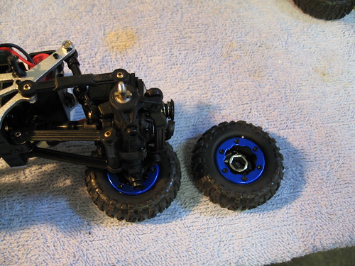 Step 1 Remove the wheel nut from the rig with the supplied plastic wrench and pull the wheel off. You will notice the the hex drive probably stayed in the wheel and exposes the drive pin on the axle. Just push the hex out of the wheel from the outside and slide it back on to the axle to not lose the pin. Edit: I could NOT get the hex out of the silver wheels in the photos! The black chrome from the other rig came out easy. If yours don't come out, just be careful not to lose the pins! 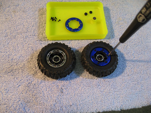 Step 2 Just remove the inner "bead lock" by taking off the 6 little screws. You will now see that the tire is glued to the rim.  Step 3 I use a new blade in an X-acto to cut the rubber off the rim. I do this by stretching the tire off the rim and making light cuts (slowly and carefully!) at where the rubber meets the plastic. Continue the whole way around with patience! You might get lucky and find that a portion is not completely stuck and comes off with a gentle pull, I had this on a couple of the 8 wheels that I did. Step 4 With the tire completely cut from the rim on the inside only (you took your time and cut slowly and carefully, right?), you should see the foam. I just grabbed the foam and pulled it out. Likely there will be a couple of "peanuts" (foam that has soaked up some CA in the gluing process and the foam will be stuck to the rim in those spots. Not to worry, just carefully pull or cut the foam off the rim. You should be able to accomplish this without wrecking the foam. 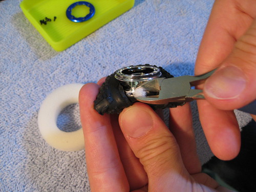 Step 5 Clean up the stuck foam residue by cutting it off the rim. 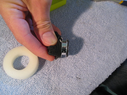 Step 6 OPTIONAL Now that you have the wheel open, it is the perfect time to add weight. You can clearly see the channel up the center of the wheel now and this is where people are "wrapping" solder or copper wire. Whichever you choose, I suggest you weigh it before you start wrapping it on, so that you get the same on both sides. If you don't have a scale, at least measure the same length for both sides! Wrap carefully and tightly. For copper wire you can secure it with a drop of CA or solder (solder may add extra eccentric weight). For solder just tack the end to an adjacent wire. 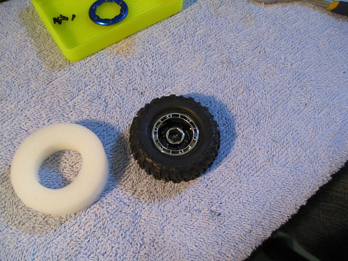 Step 7 Prep the rim and tire for re-gluing. I have found that isopropyl alcohol works well. Just dab a bit on a rag and wipe the rim gluing surface. Then wipe the tire gluing surface too. 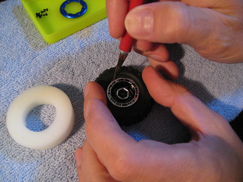 Step 8 With the tire laying down, I seat the tire on the rim (it should locate well in the cut you made). Now I put a drop of CA on a scrap piece of plastic and dip the knife blade into the glue. Now I take the whetted blade and dab it between the rim and tire. Continue around the tire. I have read others just putting 4 dabs equidistant. This should work fine, I'm just paranoid about the tire coming off (old fear from racing high powered cars and trucks...). Step 9 Put the bead lock back on. If you din't use too much glue it should look like it did when you took it apart.  Step 10 Put the wheel back on and just snug down the wheel nut. Over-tightening the wheel nut can cause SERIOUS binding issues (voice of experience). Phil. Last edited by pilmat; 08-20-2010 at 10:19 AM. Reason: Adding info and photos |
|
| |
|
08-20-2010, 08:00 PM
| #4 |
| Rock Crawler Join Date: Dec 2005 Location: houston
Posts: 650
|
Great pictures and documentation, this will surely help some who are unsure on the techniques. Keep it up, I'll be watching this one to see how it comes along.  |
|
| |
|
08-20-2010, 08:50 PM
| #5 | |
| Rock Stacker Join Date: Aug 2010 Location: Montreal
Posts: 51
| Quote:
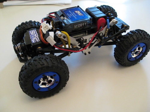 Mods so far: springs off elastics for anti-droop tire foam out rotate tranny 180 degrees WOW, it can actually climb and descend now! Removing the springs and the subsequent lowering of the springs really helps. But this is NOT a solution, only a band-aid until the parts start showing up (see below list). With no ride rate (it is just bottomed out on the shock bodies), articulation is poor and inconsistant making getting through tough lateral transitions awkward if not impossible. As a simple test, I ran the other rig without the anti-droop elastics and it is almost as bad as stock (flops through the sections, yuck!). You ma also notice I reversed the rear tire direction. This is a trick that works in off-road racing (especially stock Slash tires on moist tracks), I haven't A-B tested it yet. 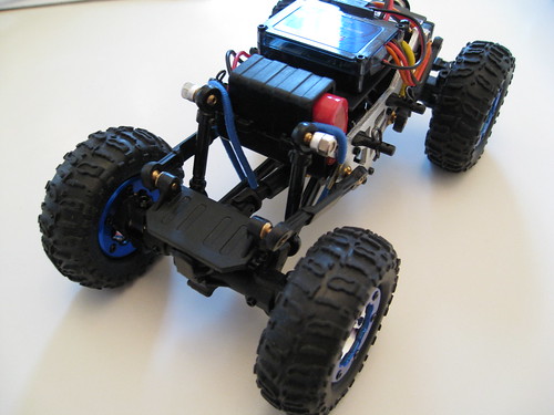 Test tomorrow: solder wrap on fronts (25" of 1.6mm solder) with 35 BBs front & rear (front 28g & rear 20g total) Looking forward to some traction. Once the below BWD weights arrive, I should be able to get the total weights up. Test list: DP chassis (will boil prior to running) BWD Wedge chassis Sven's Pinch chassis BWD wheel weights Everything is in the mail (soooo slooowwww in Canada...) First goal is to make a minimum mod rig and build it up from there. Racing slots tomorrow (our first enduro of the year), so the rigs will wait a bit. Phil. Last edited by pilmat; 08-21-2010 at 06:25 AM. Reason: Add photo and comments | |
|
| |
|
08-22-2010, 09:17 PM
| #6 |
| Rock Stacker Join Date: Aug 2010 Location: Montreal
Posts: 51
| Fitting a Hitech 65HB Servo 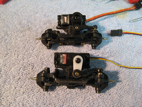 After running a couple of packs with wheel weight (30g F /22g R), I noticed that the servo saver was constantly working at the bottom of steep descents that have a sharp corner. As I'm still low on wheel weight (compared to what I have read others are running), I was concerned about this. So I read around for recommendations and then went through the specs of the servos, finally I opted for a Hitech 65HB. It weighs in 1g lighter than a stock (stock w/servo saver and 65HB with arm), but measures 23.9 mm versus 22.6 of the stock. This means it is NOT a drop in replacement as it cannot fit in between the servo posts (see the splayed open posts in the below photo). 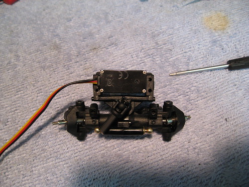 I did manage to drop it in with just a few little tweaks: 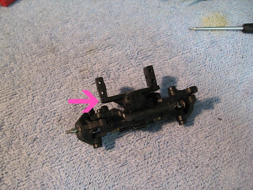 By turning the RH servo post around the fit is just perfect. Looking at the posts, you notice that there is an undercut on the axle mounting. By reversing the post, you move the post out by that amount. But there is also a mounting boss for the upper link only on the original outer surface. When you reverse the post, the overal width only increases by 0.9mm, however that is only to the right. This is not ideal but very minimal. 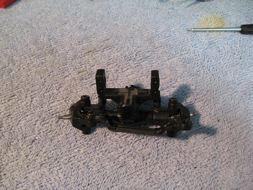 Next small snag is that the servo does not sit flat, due to a slight bulge in the center of the axle housing. I just touched it up with a file. Now the servo sits perfectly flat, but the holes in the posts don't line up with those in the servo! I filed the servo holes into slots to get everything to line up. 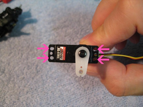 I chose the two-legged servo horn and cut off the top leg. The second hole from the center was the one that was closest to the stock arm length. I drilled out the arm with a 2.3 mm drill and tapped it with the ball. 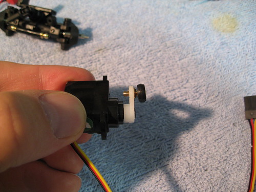 The ball threads protruded too far and touched the axle housing on sweeps to the right (it only grazed it but still not good). A little filing took it down to the right hight. I chose to shorten the thread as opposed to putting washers under the ball to keep it as close to the axle as possible, it snags enough as it is. 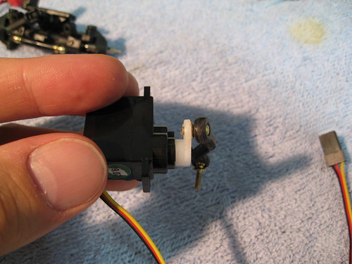 Speaking of snagging, The drag link catches every now and then too. So while I was at it with the Dremel, I put a radius on it.  I just ran a single pack on some really simple obstacles to see if the offset of the right front upper link showed any negative effects. The verdict is that if I hadn't known I wouldn't know! One other important nicety about the servo is that the cable is much thinner and more flexible (although considerably longer). I will look into shortening it when I do the second rig. I'll give it a good thrash tomorrow and also go over some findings from the weekend's crawling. Phil. |
|
| |
|
08-23-2010, 06:57 AM
| #7 |
| Quarry Creeper Join Date: Apr 2006 Location: the creek
Posts: 396
|
great pics! I need to spend some more time on my micro soon...
|
|
| |
|
08-24-2010, 10:36 AM
| #8 |
| Rock Stacker Join Date: Aug 2010 Location: Montreal
Posts: 51
| Droop Suspension Thoughts As most realize very quickly, the simplest way to get ANY crawling performance out of a stock McRC is to just remove the springs. While this can be done in about 2minutes (if your fingers are not too thick), the flopping about is only marginally better than stock when on steep climbs or descents. Even the addition of wheel weight (see above post for how much of what) is reduced in effectiveness by the flopping. Plus when at full lock the wheels touch the upper links causing instant chassis jacking which only makes things worse. Now I have 3 different chassis in the mail, but being impatient with my new toys, I went looking for some temporary cheap solutions. After reading and seeing the anti-droop solution, I raided my wife's drawers for some elastics. I found 8 that were of a good size, but maybe just a bit on the stiff side. I tried two configurations: loosely hanging on the lower arms and wrapped tighter around the lower arm axle ball. The tighter configuration is horrible, it is just a rigid board, so it immediately was scrapped. The loose configuration allows for a bit of articulation, but is not completely anti-droop. However, the climbing and descending performance is reasonable. The photos below have both configurations, the tight one is not good, but you see what I mean. 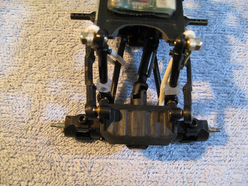 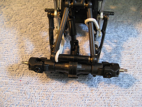 Two things become apparent with the spring removal: you lose too much ride height and when the rig returns to ride height (like after an articulation) without springs it "bangs" against the shock body causing an upset. I cured both problems with the same fix. Simply adding some fuel tubing, but sideways as in the photo, gave some extra ride height and provides minimal shock absorption. The fix is not ideal, but in my quest for a cheap band-aid until my chassis arrive, it works quite well. I "drilled" the holes in the fuel tube with a sharp xacto blade and just pushed the shock shaft through the holes. The above photos have the fuel tube mod, but this one I think is a little easier to see. 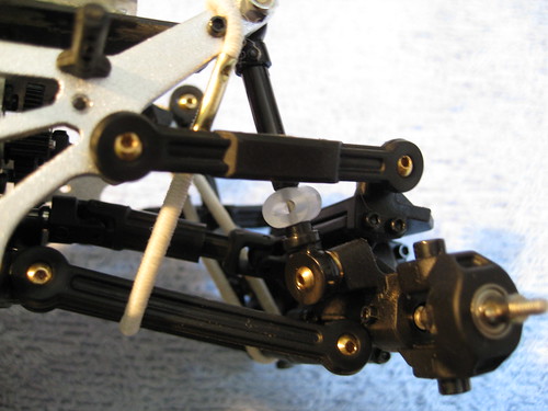 Remember that all the above is done with wheel weight. Just removing the foam helps a bit, but weight is the single best mod you can do. Phil. Last edited by pilmat; 08-24-2010 at 10:57 AM. |
|
| |
|
08-24-2010, 11:07 AM
| #9 |
| Rock Stacker Join Date: Aug 2010 Location: Montreal
Posts: 51
| Cheap & Light Chassis Braces In removing the high plastic (ESC case, ESC tray and battery tray) from the chassis, you will need to put something back to keep a bit of rigidity in the chassis. For a simple, quick and light fix. I cut the lower arm off the ESC tray and shaped it smaller with a dremel. It is now 1.0g and hols the ESC out of harm's way (after de-casing and shrink wrapping). For the other brace, I cut a WD-40 spray tube to the right length and used the screws to hold it in place. This weighs 0.1g! INSTALLED - The elastic is popped off to show the installation better 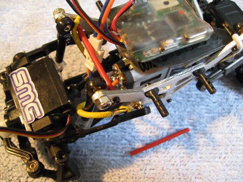 TOP 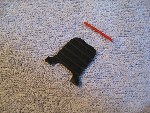 BOTTOM 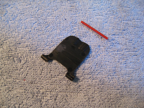 Phil. |
|
| |
|
08-24-2010, 12:04 PM
| #10 |
| Quarry Creeper Join Date: Jan 2009 Location: Pacific Northwest
Posts: 295
|
Great thread! Watching with interest!
|
|
| |
|
08-24-2010, 03:48 PM
| #11 |
| Rock Stacker Join Date: Aug 2010 Location: Montreal
Posts: 51
|
Mail call! Got my package from BWD (thanks Don). Tomorrow we build a Micro Wedge and bolt on some wheel weights. I say tomorrow 'cause I'm out tonight, but I could get started when I get back... Might be a late one. Love this hobby! Phil. |
|
| |
|
08-25-2010, 09:50 PM
| #12 |
| Rock Stacker Join Date: Aug 2010 Location: Montreal
Posts: 51
| BWD Micro Wedge Build 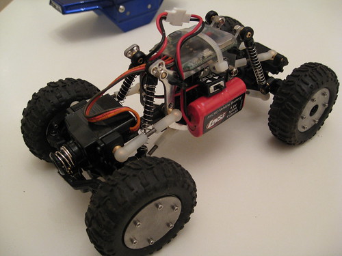 First off, these are some nice parts. These are the first micro parts I buy and the quality for the price is just fantastic. All the parts and hardware you need is in the bags. Just use the link for the build instructions. No point in putting up a bunch of photos that are well covered in the instructions and other great build threads here, I'll just cover a couple of points I came across. Lower Motor Pole Clearance  The only snag I had on assembly was that the lower motor pole fouled the chassis. Now my motor had a HUGE blob of solder on there, but even with that removed, I had to solder the wire in really flat. The instruction pictures show it quite tight too, so just pay attention when putting the right side plate on. Rear Suspension Holes The instructions call for the upper link inboard balls to be mounted in the middle holes. In this position, the cups touch the drive shaft before the suspension bottoms. So I installed the balls in the upper position. Next I moved the rear shock mount to the upper hole as I found the rig had way too much rake. I did this before driving, so it might be required. Testing will confirm. Lower link Ballcup Trimming 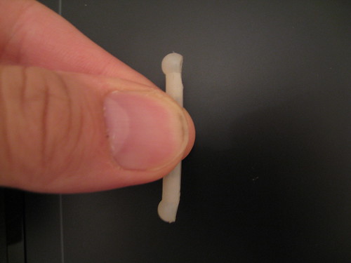 The ball cups foul on the lower balls (well documented in the instructions). I am not a big fan of removing too much material on ball cups, so I found this was the minimum required. The inboard cups (lower in the above photo) need to be cut at a small angle from the rod to the outer edge. The outboard cups need the opposite, cutting from the outer edge toward the rod, and then I put a similar cut in the cup shank. Bellow is them installed (not as easy to see). 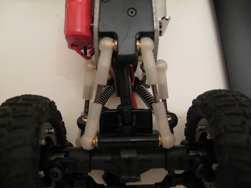 I did a couple of test packs over simple obstacles, but the result is quite impressive. With my above anti-droop stock truck, I really had to pick my lines. But with the Wedge I could ham fist it a bit more and get away with it. The addition of the excellent BWD wheel weights brings my per wheel weight to 42g front and 29g rear. Tomorrow I tackle the Metro Slot Car mountain! Phil. |
|
| |
|
08-25-2010, 10:06 PM
| #13 |
| Rock Stacker Join Date: Aug 2010 Location: Montreal
Posts: 51
| DP Torsion Chassis 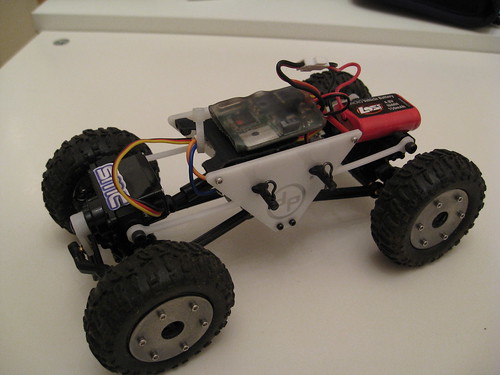 Just as I was completing the above Wedge, the mail lady came by with today's delivery: a DP Torsion chassis. Immediately I boiled the chassis for 30 minutes. I left it white, it just looks custom that way. Also, after reading how good the chassis performs with a "loose" set-up, I dug through my bolt bag and found four 2.5 mm cap head screws that were 1mm longer than the ones DP provide with the chassis. With 3 turns in, these seem well solid and have lots of "loose" for articulation (pink arrows below). Loose Set-up of Chassis Screws  The blue arrow is pointing to the On/Off switch that I servo taped to the inside of the chassis. It's well out of the way, but still easy to access. Others have covered this chassis build very well and there is an excellent thread here, so there is not much else to say. The build is very easy and straight forward. The only custom tweak is the lightened ESC tray and tube brace that I covered before. Articulation is excellent and the two test packs I did showed very promising results. Per wheel weight is set to 42g front and 29g rear. Tomorrow I hit the mountain and will report back with findings. Phil. |
|
| |
|
08-26-2010, 07:47 AM
| #14 |
| Quarry Creeper Join Date: Apr 2006 Location: the creek
Posts: 396
|
I want picks of metro slot car mountain! I've been holding off on building a course for the winter, and to integrate it with my sons slot cars would be a great idea to kill two birds with one stone |
|
| |
|
08-26-2010, 01:53 PM
| #15 | |
| Rock Stacker Join Date: Aug 2010 Location: Montreal
Posts: 51
| Quote:
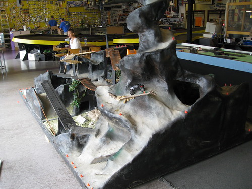 Here you can see the commercial slot car track and store in the background (and my wife ...). I put the DP rig on the hill so you can get an idea of the size.  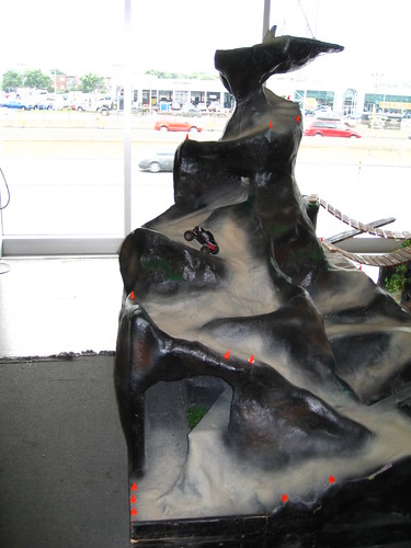 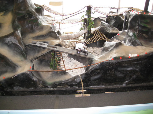 Later, Phil. | |
|
| |
|
08-26-2010, 09:27 PM
| #16 |
| Rock Stacker Join Date: Aug 2010 Location: Montreal
Posts: 51
|
Put together little video of the first proper test of the BWD Wedge and DP torsion chassis. http://www.youtube.com/watch?v=WlOx-NuEyJU Observations: The Good
The Not as Good
Battery Test: After the video testing, I installed a Thunder Power 1S 20C 350mAh pack in the DP (it just is easier to mount for a first test). WOW! Punch feels as good as the stock battery, but there seems to be more low end torque available (this could be the slightly lower average voltage). It ran for 30 MINUTES and was down to 3.6 V, so an easy 40 minute run would have been possible, although I am very pleased with 30 minutes. This is now going to be my standard set-up and will be used for all further testing. It was a fun day and cool to edit together a video. I would live some feedback on the video so improvements can be made for the future. Cheers, Phil. |
|
| |
|
08-30-2010, 05:56 AM
| #17 | |
| Rock Stacker Join Date: Aug 2010 Location: Montreal
Posts: 51
| Quote:
DP Torsion Observations The only modification to the DP equipped rig since the video is the battery swap to the 1S 350mAh. The "bounce" seen in the video is getting worse with time. As the tires are now quite dusty too (maybe they just need a good clean), there are sections I can no longer do. This rig it some 22g lighter than the Wedge, and almost all of that is in sprung weight (on the chassis). It seems as if with a fully lightened set-up that the "springs" are too stiff in ride (vertical) but that the articulation is good, probably because it is more a function of total axle weight. Here is my test plan the DP:
BWD Wedge Observations This rig is really capable. It rewards careful inputs that are at low power and very smooth (not jerky blips on the throttle). The narrow rear linkage configuration does not provide a lot of lateral stability, so whole rear end tends to "wag" in your hand. However, this does not seem to provide any ill effects while driving. Fitting the slightly bigger LiPo caused me a bit of initial concern, but a good fix was not far away. The way the Wedge is designed, the chassis plates sit around the motor and transmission, so the bulge on the left tranny case does not provide a flat surface to mount the battery. No problem though as there is a LOT of meat on the plastic and I took it and the motor plate down to flat. Now the battery mounts to it and also is servo taped to the upper rear link nut. It is very secure there. This rig is now quite good in this set-up apart from the rear maybe being too high and stiff (I'm in the upper shock hole already). After I play with that a little, this truck will be my comparison basis. If anything can do what the Wedge can do, it is good! Test plan with the Wedge:
I'll be out of town most of this week and only back after Labour Day, so most of this work will only happen then. Can I get some feedback on the video I posted? I will be doing some more soon and would like to know what I can do to improve them (dynamic camera, actual sounds, different angles, etc.). Cheers, Phil. Last edited by pilmat; 09-07-2010 at 09:09 PM. | |
|
| |
|
09-07-2010, 09:37 PM
| #18 |
| Rock Stacker Join Date: Aug 2010 Location: Montreal
Posts: 51
| Flat Battery Placement on a BWD Wedge Here is the photos of the Wedge transfer case shaving for flatter battery placement. Here is the case and motor plate shaved flat: 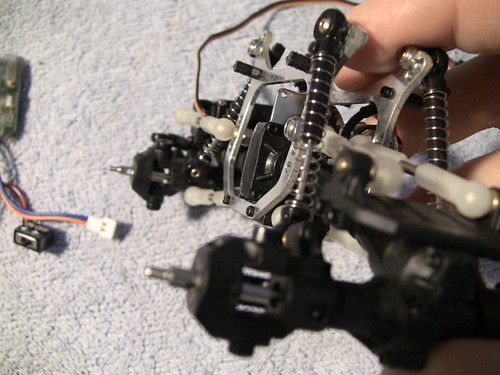 Here is the battery installed and flat (note the little servo tape on the rear link nut): 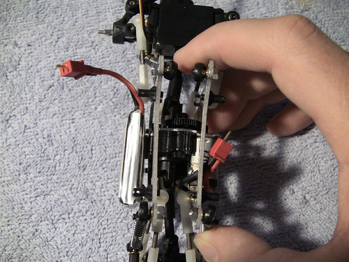 Re-Wiring the ESC/Receiver Fitting the On/Off switch can be a pain, so I removed it and replaced it with a wire. Now the act of plugging the battery turns the ESC on (binding works as before). I also replaced the stiff stock wires with silicone 20G wire, this also allow the battery wire orientation to be changed (see the photo of the underside). Top (note the red wire replacing the switch): 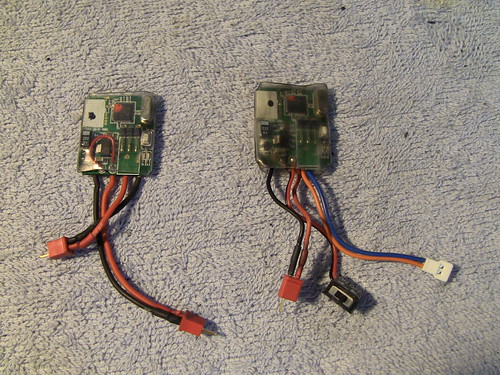 Underside (not the battery wires are no longer folded back): 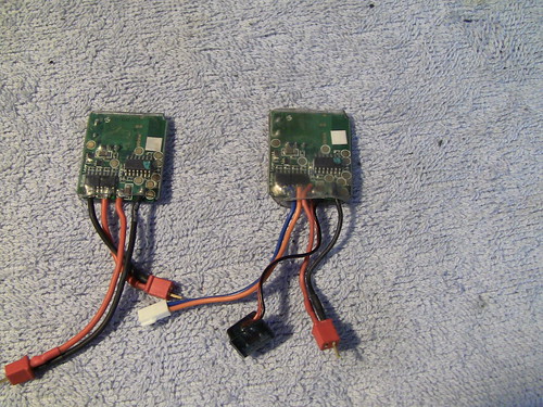 Finished as installed on the Wedge: 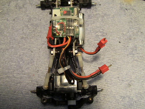 Phil. |
|
| |
|
09-11-2010, 02:25 PM
| #19 |
| Rock Stacker Join Date: Aug 2010 Location: Montreal
Posts: 51
| Clean Tires Not enough can be said for the benefit of clean tires. Just spaying a little Simple Green on a rag and then dabbing it onto the tires, transformed a couple of really tough sections into ones that became quite do-able. The DP chassis rig is very light and the spring rate is pretty high, so it really benefits from clean tires. P.S. Let the Simple Green dry completely. The tires become nice and tacky. The DP Torsion and Wheel Weight As a newbie crawler, I am learning all about the delicate balance of front-to-rear wheel weighting. The starting point of 42 g per wheel front and 29 g rear came from suggestions I read on here (mostly Dogbreath's excellent guidance). After watching the DP struggle up certain climbs with lack of bite (which quickly dissolves into chassis bounce and a no-go over an obstacle), I added 7 grams to my 42 g initial front per-wheel-weight. WOW! Obstacles suddenly became easier and climbing improved. Next I added 7 grams to each rear wheel. It went right back to its struggling and bouncing! So that was quickly undone and I then REMOVED rear per wheel weight down to 22 g. Now the performance is as good as the 49/29 g set-up but with less overall weight. Now the balance has to be fine tuned a bit more, but it seems it responds well to a large difference. Lots more to come! Cheers, Phil. |
|
| |
|
09-15-2010, 09:27 PM
| #20 |
| Rock Stacker Join Date: Aug 2010 Location: Montreal
Posts: 51
|
The Pinch chassis from Sven just showed up :-). I have already put one on a box stock truck and will do a write up on the other one (I ordered two). The short story is that it goes together really well except for two minor glitches (more in the write up). The write up might take a few days as my MRC Pro is due tomorrow!!!! Later, Phil. |
|
| |
 |
| |


 Linear Mode


