| |
 02-24-2012, 07:20 PM
| #181 |
| I wanna be Dave Join Date: Nov 2010 Location: 07456 N. NJ USofA
Posts: 8,314
|
Nice drawing. It appears correct to me. I also wire the BEC direct to the servo.  I would look towards ditching the on/off switch. |

|  |
| Sponsored Links | |
| | |
|
02-25-2012, 01:45 PM
| #182 |
| Newbie  Join Date: Oct 2010 Location: Central Mass
Posts: 37
|
Solder the 2 switch leads together to do that, right?
|
|
| |
|
02-25-2012, 07:01 PM
| #183 | |
| I wanna be Dave Join Date: Nov 2010 Location: 07456 N. NJ USofA
Posts: 8,314
| Quote:
| |
|
| |
|
03-09-2012, 09:22 PM
| #184 |
| Pebble Pounder Join Date: Sep 2011 Location: USA
Posts: 157
|
Would 24 gauge wire be to small to make extension cables for my electronics? Esc to rx. Servo to rx. Castle bec to servo. Only running some 5mm LEDs from rx and using hitec 7955 servo. Sent from my iPhone using Tapatalk |
|
| |
|
03-09-2012, 09:33 PM
| #185 |
| Quarry Creeper Join Date: Feb 2012 Location: SAN DIEGO
Posts: 242
|
Yeah! 24ga is fine if its good wire. Turnigy is common and is a heavy stranded wire. Stock 7955 leads are 24ga. Make sure you wire that servo to your bec like the awesome diagrams on this thread show and the Hitec will be happy. |
|
| |
|
03-09-2012, 10:00 PM
| #186 |
| Pebble Pounder Join Date: Sep 2011 Location: USA
Posts: 157
|
Cool got the wire. I just realized hitec was 24 lol. Yes I'm wiring it like the diagrams! That servo is what I have now but plans to swap it out for hitec hv servo in the future. Thanks for your help! Sent from my iPhone using Tapatalk |
|
| |
|
03-30-2012, 05:11 PM
| #187 |
| Quarry Creeper Join Date: Feb 2011 Location: Lynnwood
Posts: 241
|
I am planning on connecting my BEC directly to the Servo. However, i kinda have a hick-up! When i got my new ESC's i cut the red wire pin off...completely. But i dont want to solder or crimp a pin on. Here is my current set up..  To power the Rx i would need the red wire connected. Could i solder a jumper wire from the BEC to power the Rx?  Trying to be a cheap a$$ and keep from buying pins and a crimper. And yes.. i have search. Have not found anything like this.  |
|
| |
|
03-30-2012, 06:40 PM
| #188 | |
| I wanna be Dave Join Date: Nov 2010 Location: 07456 N. NJ USofA
Posts: 8,314
| Quote:
Is there enough of the wire left to reconnect it together?? You can either plug the external BEC into the RX to power everything, or fix the ESC to RX red wire & wire the BEC direct to the servo. | |
|
| |
|
04-13-2012, 10:18 AM
| #189 |
| Quarry Creeper Join Date: Feb 2011 Location: Lynnwood
Posts: 241
|
So i went out and got some pins and a crimper. What i did was: 1. re-pin one of the red wires on the ESC. 2. Cut the BEC wires shorter and re-pinned the Brown and the Red wires with male pins and re-pinned the orange wire with a female pin. 3. Cut the servo wires to fit and re-pinned with female pins. 4. Using the cut BEC wires, removed the orange wire from the connector, cut the remaining two wires to match the length of the original orange wire from the BEC. 5. Soldered the brown and red wires to the BEC. Taking the original orange wire and the two new soldered wires and put them into a connector. 6. Using the cut servo wires, took the yellow wire and on the cut end, re-pinned with a male pin. 7. inserted the yellow male pin into the BEC connector that has only the brown and red wires. This allows me to have a connector so that i can adjust my BEC without having to undo connections. This also allows me to replace a servo without having to cut and re-pin (unless i want to shorten the wires). Here's a couple images  and  |
|
| |
|
05-14-2012, 11:59 AM
| #190 |
| Quarry Creeper Join Date: Jun 2010 Location: Ireland
Posts: 433
|  I may have missed this, but why should the positive wire between the Rx and one FXR be disconnected? |
|
| |
|
05-14-2012, 12:09 PM
| #191 | |
| I wanna be Dave Join Date: Nov 2010 Location: 07456 N. NJ USofA
Posts: 8,314
| Quote:
If you run the external BEC into the RX (not what I like to do) then you need to remove BOTH ESC to RX red wires. | |
|
| |
|
05-31-2012, 08:30 AM
| #192 |
| RCC Addict Join Date: Jun 2010 Location: Australia NSW
Posts: 1,266
|
Just read this whole thread. wow. lol. tons of back n fourth info. its a wonder anyone with limited knowledge could decipher any of it!! lol.... now, i had a concept in mind, but now its dawned on me, i probably still need a BEC between my Lipo and my RX, unless i do it slightly differently and use the ESC BEC to run the RX and just use the lipo to run the (now 2x) servo. Its a MOA 1/8 HSP climber. running the stock ESC but x2 and whatever the stock servo is on the front, and then an old JR NES505 on the rear. and double 16t brushed motors. some V8 thing. pretty powerful. (might be a bit much actually) anyway, heres version #1 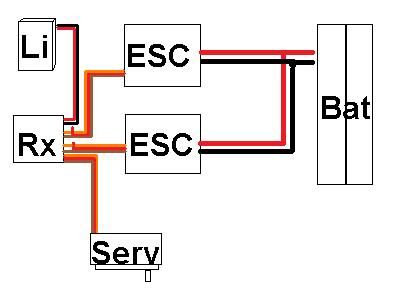 I have since had a play with physical bits n bobs, and i think my plan is: * run the two ESCs each with its own 2S Lipo * have one of the ESCs BECs connected to the RX for its power. * and to have a third small Lipo purely to power the Servos (but will 7.4v fry a "normal" servo??) opinion? |
|
| |
|
05-31-2012, 08:59 AM
| #193 |
| RCC Addict Join Date: Jun 2010 Location: Australia NSW
Posts: 1,266
|
heres V2 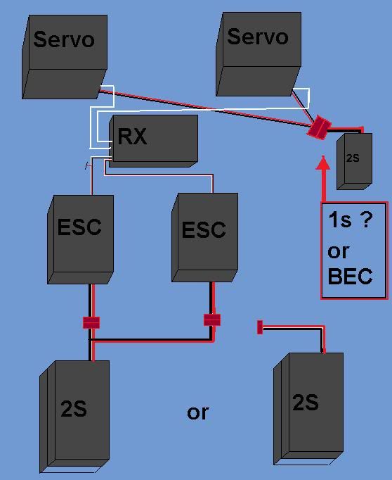 |
|
| |
|
09-19-2012, 02:54 PM
| #194 |
| Quarry Creeper Join Date: Jul 2009 Location: Dublin,Ireland-Cluj,Romania
Posts: 446
|
need some help.i have 2 tekin fxr,1 CC bec,1 dig unit on a xr10,how should i do the wiring?thx |
|
| |
|
09-19-2012, 04:15 PM
| #195 |
| Newbie Join Date: Oct 2010 Location: Central Mass
Posts: 37
|
If you have 2 FXRs, you shouldn't need a dig unit. Wire it as Harley describes here: Harley's Complete XR10 Guide If you meant you have 1 FXR and a dig unit, wire it as I did in post #180. Worked great for me. |
|
| |
|
09-19-2012, 06:23 PM
| #196 | |
| I wanna be Dave Join Date: Nov 2010 Location: 07456 N. NJ USofA
Posts: 8,314
| Quote:
As mentioned, 1 ESC & a dig, or 2 ESC's and a radio that can use them. | |
|
| |
|
09-20-2012, 09:18 AM
| #197 |
| Quarry Creeper Join Date: Jul 2009 Location: Dublin,Ireland-Cluj,Romania
Posts: 446
|
i have the dig unit,because i have the spektrum dx3r and from what i know it has only 3 channels and needs the electronic dig unit P.S. here what the producer says,NOVAK: The Dig Unit interfaces between any two sensored or non-sensored brushless or brushed systems; the Dig can even operate on one brushless and one brushed system. The Dig mixes the throttle channel with a three position, or proportional, third channel. The transmitter does not need a mixing function to operate The Dig. All of the mixing is done within The Dig Unit itself. Two different-colored LED indicator lights – located at the ends of six-inch harnesses for easy and countless installation possibilities – visibly display when a speed control is locked and ready to dig. The Dig is easily programmed into most three-channel transmitters, such as the Spektrum® DX3R DSM2 3CH Surface Radio™, Airtronics’® M8 and M11 R/C Radios™, and a Traxxas® (TQ-3) Transmitter™.* Last edited by Kitty; 09-20-2012 at 09:23 AM. |
|
| |
|
11-07-2012, 02:13 PM
| #198 |
| RCC Addict Join Date: Mar 2009 Location: Interior BC
Posts: 1,786
|
i just wired in my BEC like this pic.... My MMP functions properly but im not getting any servo response? +/- from battery to BEC +/- from BEC to servo Signal from servo to Rx the LED lights up on the BEC, so its good there?? 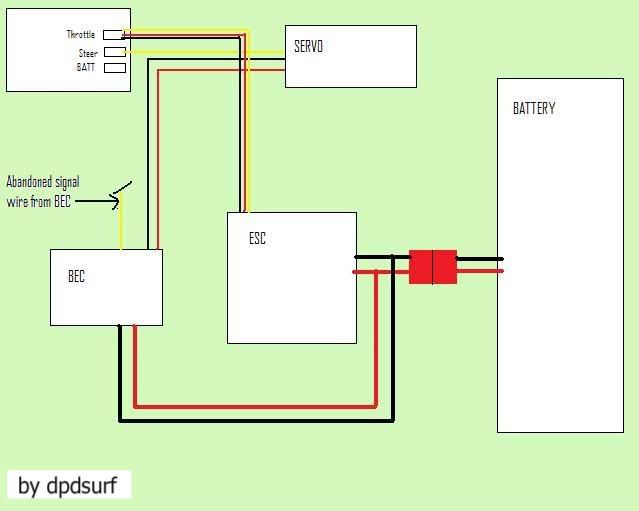 |
|
| |
|
05-30-2013, 01:31 AM
| #199 |
| Newbie Join Date: May 2013 Location: Perth AU
Posts: 37
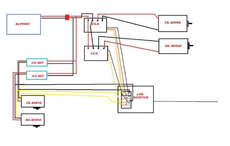
| Here goes with my electronics build, Ive not done any soldering for 10+ years so I apologise if the soldering looks like a dogs dinner! Thanks go to Highlucks and the guys at OneTenCrawlers for their advice…. Kit: CC BEC (set to 6v, thanks to Highlucks ) power wires resoldered to come out the same side as the Rx cable3 into 1 servo hub/Rx bypass adapter (more on this later. Can use a 2in1 LHS only had a 3:1) FXRs x2 – not smashed (im not bold enough or good enough with my soldering!) Heat shrink 14AWG wire throughout 3.5mm gold bullet connectors soldered direct to FXR posts Soldering Iron Flux Hitec 5955tg Hobbyking 6Ch Rx New female 3hole servo connectors First off was to find the right wiring diagram for the above list. I wanted to achieve the following: · To power the Servo using 6.0v from the BEC direct from the battery so as not to fry or brown out the Rx under heavy loads. · I still needed to get the signal from the Rx · Not cut the BEC wiring (so I can still program it in the future) · Power the Rx from the FXrs · I didn’t want to “test” the Hobbyking Rx to find out. Lots of wiring diagrams out there, some for MOAs, some for DIG and some of them wrong so I drew my own so I was clear in my own mind. You can see this is where the hub comes in useful because you can “pull” the +ve red cable out without damaging the BEC wires/connector. 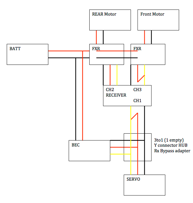 I was constantly dry testing the setup with my motor mounted electronics tray to keep the wiring as short and neat as possible. I used the 3.5 bullet connectors straight off the FXR posts for the motor wires so I could remove them etc easily and it didn’t make the 14awg too stiff ‘mid cable” Last edited by The gasman; 05-30-2013 at 10:27 PM. Reason: Edited the wiring diagram to put just one +ve feed to Rx |
|
| |
|
05-30-2013, 01:32 AM
| #200 |
| Newbie Join Date: May 2013 Location: Perth AU
Posts: 37
| The XT60 plugs use 3.5mm connectors and the nanotech 3s 1300mah battery uses 14g wires so I didnt see any need in going heavier in gauge or connector size. Feel free to correct me if Im wrong but so far very little hot wires after use So a few hours of soldering later I came up with this BEC, yet to be black shrink wrapped, they ran out at the LHS! 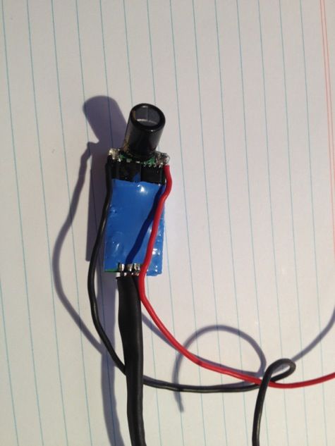 FXRs with bullet connectors and power supply crossover 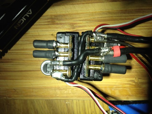 3 into 1 hub joining BEC power to Servo but still receiving Rx feed from Ch1 (you can see the red power cable pulled from the connector in the background) 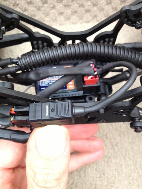 Cut off the switches to the FXRs and soldiered them permanently on then trimmed the excess Rx cable, heat wrapped and fitted new Rx connectors to get rid of excess cabling in the body. I didnt shrink the wrap all the way because it gets too stiff. 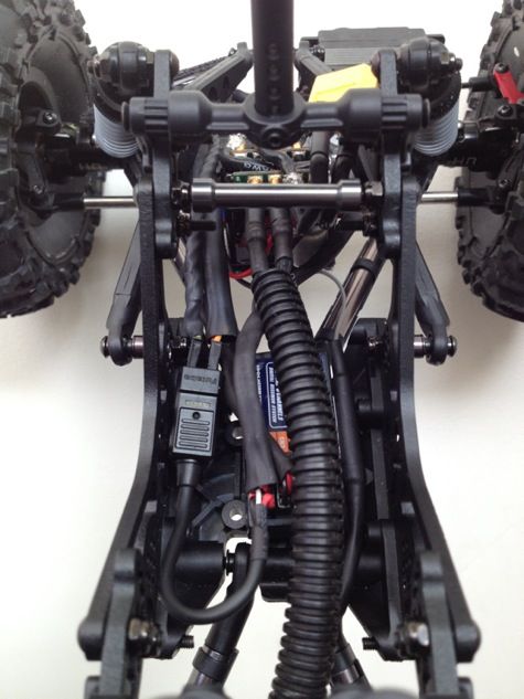 Motor wires . Front, you can also see the FXRs and BEC on my motor mounted electronics tray J 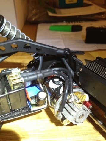 Rear with cable wrap just to look different J. And 35mm camera roll case to act a protector for the motor 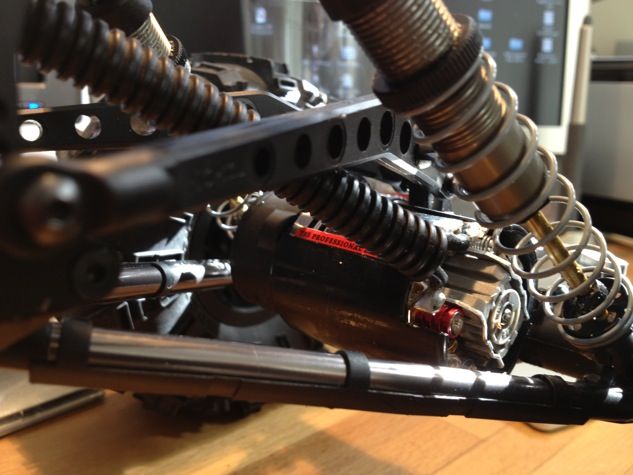 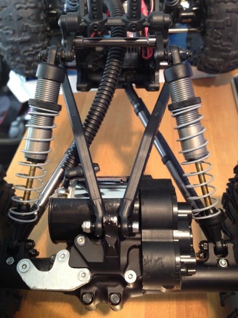 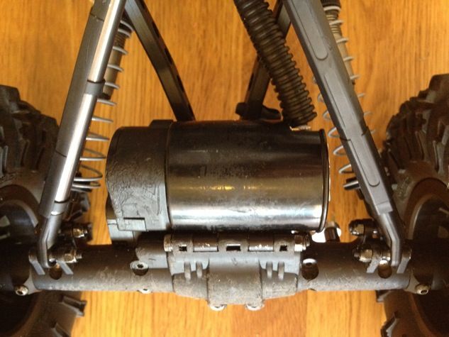 Overall I think the cables are pretty tidy and I like the all black stealth look, (XT60 also waiting for the black shrink wrap from the LHS!! It has kept the centre of gravity low and the body is pretty empty. 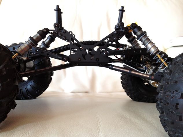 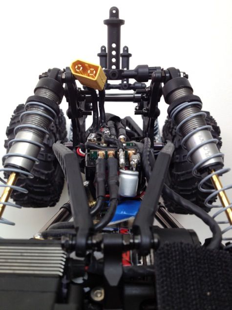 Its just a shame Im so s**t at soldering!!! Hope you like it and it helps anyone out there who is as confused as i was !!!. |
|
| |
 |
| |


 Linear Mode


